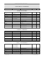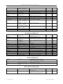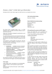
1
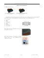
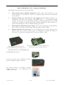
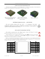
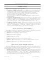
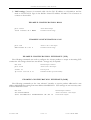
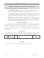
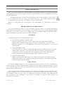
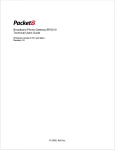
U S E R M A N UA L
OV E RV I E W
Avisaro 2.0 Product Series
Data Logger Box (SD)
WLAN Device Server (2.0)
Ethernet / TCP
Logger Box (SD)
Data Logger Module (SD)
WLAN Module (2.0)
Other configurations
Version 1.2
2008.02.12
A VIS ARO 2.0 C OMPACT U S ER MANUAL
THIS DOCUMENT
HISTORY
2008-01-01
Initial version
2008-02-07
Added CAN commands table
2008-02-12
Added Ethernet (TCP und raw) commands
REQUIRED FIRMWARE
This document describes firmware version 1-16 or higher.
Navigate to the relevant product page on www.avisaro.com to download latest firmware versions.
CONTACT
Avisaro AG
Vahrenwalderstr. 7 (tch)
30165 Hannover
Germany
Telephone:
+49-511-7809390
Telefax:
+49-511-35319624
eMail:
[email protected]
A VIS ARO AG
PAGE
2
DATE :
08.02.2008
A VIS ARO 2.0 C OMPACT U S ER MANUAL
TABLE OF CONTENT
This Document .................................................................................................................................................................................. 2
History
2
required Firmware
2
Contact
2
Table of Content................................................................................................................................................................................ 3
About this Document ....................................................................................................................................................................... 4
Connect and Power UP .................................................................................................................................................................... 5
Box: RS232 Interface
5
Box: CAN Interface
6
Box: Ethernet (TCP / raw) Interface
7
Base and Trailor Modules
8
Interface (RS232, I2C, SPI, …) selection
8
Pin Layout and Signal Levels
8
Watch out
9
Configuration.................................................................................................................................................................................... 10
Default values for Data interface
10
Default values for network interface
10
Example configuration: RS232
11
Example configuraiton: CAN
11
Example configuration: Ethernet (TCP)
11
Example configuration: Ethernet (raw)
11
Command Interface vs. Packet API vs Scripting....................................................................................................................... 12
Command Interface
12
Packet API
12
Scripting
12
BASIC Scripting............................................................................................................................................................................... 13
Programming Environment
13
Loading
13
Execution
13
Building blocks................................................................................................................................................................................. 14
Base Module
14
Trailer Modules
14
Connector Boards
15
Firmware Update ............................................................................................................................................................................. 16
Firmware Update using web interface
16
Firmware Update using a SD memory card
17
Firmware update using data interface
17
Attachment: Commands................................................................................................................................................................. 18
Interface control
18
General commands
18
WLAN / LAN Interface
18
SD-Card Interface
19
BASIC Scripting
19
Advanced commands
19
A VIS ARO AG
PAGE
3
DATE :
08.02.2008
A VIS ARO 2.0 C OMPACT U S ER MANUAL
ABOUT THIS DOCUMENT
This document provides a compact introduction into the functions and features of the Avisaro 2.0
Product series. Since all Series 2.0 products are similar in how to use them, this document is “one doc
fits all”.
Further detailed documentation is available:
Document
Description
Where to find
Avisaro Command Interface
Lists all commands and their syntax.
Describes packet format and other
details
www.avisaro.com
(Download section)
Avisaro Basic Scripting
Lists all BASIC commands and their www.avisaro.com
syntax. Comes with example listings.
(Download section)
Avisaro Hardware Documentation
Describes PIN layout, electrical and www.avisaro.com
mechanical dimensions of the (Download section)
products.
A VIS ARO AG
PAGE
4
DATE :
08.02.2008
A VIS ARO 2.0 C OMPACT U S ER MANUAL
CONNECT AND POWER UP
BOX: RS232 INTERFACE
Relevant products are:
Data Logger Box (SD) with
RS232 interfaces
WLAN Device Server (2.0) with
RS232 interfaces
Depending on the interface purchased, the Box comes with a SubD connector or with a WAGO
cage clamp connector. The SubD (male) connector conforms to the standard pin layout:
1
2
3
4
5
6
7
8
9
Data Carrier Detect (DCD)
Receive (RxD) Data going to Avisaro Box
Transmit (TxD) Data going to device
Data Terminal Ready (DTR) Avisaro Box is up
Signal Ground GND
Data Set Ready (DSR) Client is up and running
Request To Send (RTS) Avisaro wants to send data
Clear To Send (CTS) Client is ready to receive data
Not used (Ring Indicator (RI)
If the box comes with a WAGO connector,
the pin layout is as follows:
The barrel connector is layouted as follows.
Supply voltage is 6 – 32 V. Diameter of the
connector is 2.1mm:
A VIS ARO AG
PAGE
5
DATE :
08.02.2008
A VIS ARO 2.0 C OMPACT U S ER MANUAL
BOX: CAN INTERFACE
Relevant products are.
Data Logger Box (SD) with
CAN interfaces
WLAN Device Server (2.0) with
CAN interfaces
Depending on the interface purchased, the Box comes with a SubD connector or with a WAGO
cage clamp connector. The SubD (male) connector conforms to the standard pin layout:
1
2
3
4
5
6
7
8
9
not connected
CAN-L
GND
not connected
not connected
GND
CAN-H
not connected
not connected
If the box comes with a WAGO connector, the
pin layout is as follows:
The barrel connector is layouted as follows.
Supply voltage is 6 – 32 V. Diameter of the
connector is 2.1mm:
A VIS ARO AG
PAGE
6
DATE :
08.02.2008
A VIS ARO 2.0 C OMPACT U S ER MANUAL
BOX: ETHERNET (TCP / RAW) INTERFACE
The Ethernet connection serves for four functions:
1)
Data interface with a TCP/IP connection: Connect with a TCP connection to the
Avisaro product (i.e. 192.168.0.73 on port 23). Using this TCP connection, all commands
can be entered.
2)
Network interface for user data (i.e. data logger): Within BASIC scripting or in
combination with other data interfaces (like RS232, CAN, …) the Ethernet network
interface can be used for user defined networking (outgoing/incoming TCP and UDP
connections). Example: Automatic data logger (all data through this TCP connection is
written automatically into a file). See BASIC scripting for details.
3)
Data interface with Ethernet type 1 frames: A low level communication using Ethernet
type 1 frames is accepted. Avisaro accepts Ethernet packets its MAC address.
4)
Network interface for web server: For easy configuration, the Avisaro products have
build in web server which provides pages for configuration. Default IP address is
192.168.0.73 / default user and password for web site is: admin / 1234
Data Logger Box (SD) with Ethernet
interfaces and WAGO cage clamp for power
Data Logger Box (SD) with Ethernet interfaces and
barrel connector (shown without enclosure)
Ethernet interface is a standard RJ45 jack:
Standard Ethernet Layout
If the box comes with a WAGO connector,
power is supplied using this connector
The barrel connector is layouted as follows.
Supply voltage is 6 – 32 V. Diameter of the
connector is 2.1mm:
A VIS ARO AG
PAGE
7
DATE :
08.02.2008
A VIS ARO 2.0 C OMPACT U S ER MANUAL
BASE AND TRAILOR MODULES
The Base and Trailor Modules are the building blocks for all Series 2.0 products. The modules are
designed to be integrated into other products to become a part of their.
Data Logger Module (SD) with
RS232, CAN, I2C, SPI and
other interfaces
WLAN Module (2.0) with
RS232, CAN, I2C, SPI and
other interfaces
Other configurations
INTERFACE (RS232, I2C, SPI, …) SELECTION
The active interface (RS232, SPI, I2C, CAN, …) is configurable. The default
configuration is RS232. See next chapter “Configuration” on page 10 for how to change this
configuration (either through auto run file on SD card, web interface or data interface. I.e.
“prot i2c” for I2C interface to become active).
PIN LAYOUT AND SIGNAL LEVELS
The module is powered with 3.3V. Higher supply voltage will damage the product
permanently. Signal levels, however, can be up to 5V.
All data interface do not contain any driver circuitry. Thus: RS232 is 3.3V level. To operate
with a PC or other device, a MAX232 IC is needed. CAN is designed as Tx and RX – a CAN
transceiver IC is need to operate on a CAN bus.
Refer to the hardware documentation for details on the pin layout. As an example, the pin layout
of the module when configured as RS232 is displayed here. When configured as i.e. CAN, pin layout
changes. Power (pin 24 and pin 13) remain always power pins.
1
2
3
4
5
6
7
8
9
10
11
12
P
O
O
I
I
I
O
I
O
I
I
O
VBAT
LED1
LED2
KEY
DCD
DSR
DTR
RING
TXD
RXD
CTS
RTS
VCC (3.3V)
IN_CS0
IN_CS1
IN_CS2
IN_CS3
IN_SCK
IN_MOSI
IN_MISO
nc
nc
nc
GND
P
O
O
O
O
O
O
I
P
24
23
22
21
20
19
18
17
16
15
14
13
‘P’: Power, ‘I’: Input, ‘O’: Output, ‘B’: Bidirectional
A VIS ARO AG
PAGE
8
DATE :
08.02.2008
A VIS ARO 2.0 C OMPACT U S ER MANUAL
VBAT: Battery Supply for the real time clock. See chapter … for details
LED1: Module is up and running
LED2: Module is working (transmitting data)
KEY: Stop current action. Start defined action (data logging, WLAN transmittion)
TXD, RXD, ….: RS232 connection
IN_*: Internal SPI bus to connect trailer modules
WATCH OUT
The Avisaro 2.0 Products are high tec products designed to be used by experts. Even though their
design is robust to withstand electrical and mechanical hazards, all products should be handled with
care.
When products are not operated as designed, there is risk of damage to the products
and to other products around.
A VIS ARO AG
PAGE
9
DATE :
08.02.2008
A VIS ARO 2.0 C OMPACT U S ER MANUAL
CONFIGURATION
There are three ways to configure the Avisaro products.
1) Configuration using SD memory cards: All data logging products can be configured using a
configuration file on a memory card. Place all configuration commands (see next paragraphs
for examples and separate document “Command Interface Manual”) in a file called
“autorun.txt”. Insert card and power on module. This will always work even if all other
methods are blocked i.e. by faulty baud rate parameter.
Got no SD Card slot on the product ? See chapter “Building blocks” on page 14 on how to
add one temporarily.
2) Configuration using Web-Interface: All products with a WLAN or LAN interface can be
configured using a build in web interface. Connect your PC to the modules WLAN or LAN.
Type in the IP Address of the Avisaro module into the browsers address line. All settings are
now set by the web interface. Default user and password for web site is: admin / 1234 .
3) Configuration using Data Interface: All commands can be typed or send over the data
interface (RS232, SPI, CAN, …). Commands can be send in ASCII format or in binary packed
format (see ”Command Interface vs. Packet API vs Scripting” on page 12). See separate
document “Command Interface Manual” for the syntax of the commands.
DEFAULT VALUES FOR DATA INTERFACE
When shipped, the products are pre configured (“Default Settings”) depending on the interface
activated. Modules are preconfigured with the RS232 connection activated:
1) RS232: Default setting is 9600, n, 1 and no flow control
2) I2C: Default bus address is decimal 73
3) SPI: No special setting necessary
4) CAN: Default baudrate is 125 kbit/s. Default CAN ID is decimal 73
5) Ethernet / TCP: The data interface can be reached at ip address 192.168.0.73 on port 23.
6) Ethernet / raw: The default MAC address is printed on the product
DEFAULT VALUES FOR NETWORK INTERFACE
The network interface must be active for Ethernet TCP / raw to work. The network interface is
found automatically upon power up. If WLAN and LAN are attached, the WLAN becomes the
network interface. Only one network interface can be active as a network.
1) WLAN setting: In default mode, the Avisaro products creates an adhoc WLAN network with
the SSID name “avisaro”. Do a network search with your PC and it will show up in the list of
available networks. Connect to it. Set the PCs IP address to 192.168.0.xx and the mask to
255.255.255.0. Type in the default Avisaro IP address 192.168.0.73 in a browser to connect to
the module. Default user and password for web site is: admin / 1234 .
A VIS ARO AG
PAGE
10
DATE :
08.02.2008
A VIS ARO 2.0 C OMPACT U S ER MANUAL
2) LAN setting: Connect via network cable. Set the PCs IP address to 192.168.0.xx and the
mask to 255.255.255.0. Type in the default Avisaro IP address 192.168.0.73 in a browser to
connect to the module.
EXAMPLE CONFIGURATION: RS232
prot rs232
Activate RS232 interface
rs232 115200 8 N 1 NONE
Set baudrate and other settings
EXAMPLE CONFIGURAITON: CAN
prot can
Activates CAN as data interface
CAN 125000 49 0 49 0
Set baudrate and other settings
EXAMPLE CONFIGURATION: ETHERNET (TCP)
The following commands are used to configure the Avisaro product to accept an incoming TCP
connection. All settings shown here are default – change only if required:
net eth
Network interface to Ethernet
prot sock
Activates TCP as data interface
sockio 23
Listen on port 23
ip local 192.168.0.73
Set modules IP address (for TCP and Web)
EXAMPLE CONFIGURATION: ETHERNET (RAW)
The following commands set the “raw ethernet” interface to receive packets addressed to mac
address 02020304050a coming from mac address 0019dbb5c231. TCP settings are not necessary since
low level Ethernet is used.
net eth
Network interface to Ethernet
eth 02020304050a
Activates raw Ethernet as data interface
ethio 0019dbb5c231 ffffffffffff off off 10
Set listen MAC and filter
A VIS ARO AG
PAGE
11
DATE :
08.02.2008
A VIS ARO 2.0 C OMPACT U S ER MANUAL
COMMAND INTERFACE VS. PACKET API VS SCRIPTING
There are three modes to operate or to interact with the module:
1)
The Command Interface allows to type and send commands in ASCII format. For
example, a RS232 product is connect with a terminal program on a PC, one can
communicate by typing in commands and by reading the answer on the terminal.
2)
The Packet API is designed for programmable devices (microcontroller) to control the
Avisaro product. Commands and data are packaged in simple frames. This is a powerful
and fast way to communicate with the module. The frames contain binary data elements.
3)
Scripting is used to customize the behaviour of the module and to implement stand alone
functionality. As programming language, a BASIC like syntax is used. That is simple to
understand and it does not need a special programming environment. Typical application
would be data logging: receive data from one of the interfaces, format the data and store it
on a memory card or send it via (wireless) network.
COMMAND INTERFACE
The command interface is designed to communicate with the module ‘naturally’. When the RS232
interface is active and connected with a PC, one can type in the commands on a regular terminal
programm (such as Hyperterminal which comes with Windows). Other interfaces work the same.
There is a long list of commands to configure and to operate the Box or the Module (see
“Attachment: Commands” on page 18 and separate document “Command Interface
Documentation”)
PACKET API
The packet interface uses a simple frame format for communication. With “Internal
Portnumbers” multiple communication – such as several opened files or several TCP/IP connections
– at the same time are possible. See separate document “Command Interface Documentation”.
Header
Byte
Length
MSB
LSB
Internal
Port(*)
CRC
MSB
Payload
Avisaro Packet API frame format.
LSB
( )
* only if frame is a data frame
SCRIPTING
Scripting is described in its own chapter. See “BASIC Scripting” on page 13.
A VIS ARO AG
PAGE
12
DATE :
08.02.2008
A VIS ARO 2.0 C OMPACT U S ER MANUAL
BASIC SCRIPTING
The Avisaro Base Module has a build in BASIC programming language. It is designed to program
small applications such as data logger or device server functionality. It is not designed to write large,
complex applications.
The BASIC program is stored in the internal flash of the Avisaro Module – thus it needs
to be loaded only once. By setting the autorun flag (see ) the BASIC program starts
automatically upon power up. It is a simple yet very powerful feature.
Browse to www.avisaro.com and navigate to the “Anwendung” or “Application” section for
examples.
PROGRAMMING ENVIRONMENT
Use your preferred text editor to type the BASIC program. There is no special programming
environment since applications are not complex. For an easier start, use one of the example programs
and modify it. The source code can be 4 kByte large (with 2.8 kByte tokenised code) and 8 kByte
space for variables, arrays and other space needed at runtime.
LOADING
The BASIC program can be uploaded three ways:
1) Using the data interface (i.e. RS232, I2C):
Type the command “load” and <enter>. Than upload the textfile with the BASIC
program. Most terminal program support the option “send textfile” to do that. Finish
upload by typing in “+++” (=stopsequence). It is usefull to have the three +++ at the end
of the textfile.
2) Using a SD memory card:
Copy the textfile (i.e. “basic.txt”) with the BASIC program to a SD card. Create a second
textfile called “autorun.txt” on this SD card. Enter the following command in this file:
“load basic.txt”. Insert a newline after this command (<enter>). Place SD card into
module and power up. The BASCI program will be loaded into memory.
3) Using the Web Interface:
With a network interface (WLAN or LAN) attached, the upload can be done using the
Webinterface. Browse to the module’s home page and navigate to the BASIC page. Select
the file to upload and press submit.
EXECUTION
To execute a BASIC Script, the “run” command is issued. Using the “run auto” command, the
autostart flag is set. When the Box/Module is powered up, the script is started automatically. A single
“run” starts the script once. The run command can be issued by the data interface, autorun.txt file on
SD card and via web interface.
How to stop execution depends somewhat on the design. The BASIC script can terminate itself –
it was programmed to do so. If it was started with “run” without any flags, a power off/on cycle will
stop execution. If the “run auto” flag is set, termination can be done two ways: using a SD card with
the “autorun.txt” file containing a “run manual” command or using the Web interface (if
WLAN/LAN is present).
A VIS ARO AG
PAGE
13
DATE :
08.02.2008
A VIS ARO 2.0 C OMPACT U S ER MANUAL
BUILDING BLOCKS
Avisaro 2.0 Product Series is designed to mix and match. Just like LEGO building blocks, most
elements can be connected to get the functionality one needs. Need a CAN Data Logger with WLAN
access ?
BASE MODULE
The Avisaro 2.0 Base Module contains the main processing power to drive the WLAN or SDCard trailer modules. The Base Module is designed to piggyback the Trailer Modules and is designed
to fit on the connector boards.
Processor and other circuitry
optional on board battery for real
time clock (a pin for Vbat is
available, too)
TRAILER MODULES
Trailer modules bring WLAN, SD card slot and other functionality.
WLAN Trailer module,
piggybacked with the Base Module
SD-Card Trailer module
piggybacked with the Base Module
All modules stacked together
Experimental PCB with connector
strips for height spacing
A VIS ARO AG
PAGE
14
DATE :
08.02.2008
A VIS ARO 2.0 C OMPACT U S ER MANUAL
CONNECTOR BOARDS
Connector boards contain interface connectors, driver circuitry such as MAX232 and CAN
transceivers and power supply circuitry. A battery holder to power the real time clock is on board as
well.
CAN Board with RTC battery
A VIS ARO AG
RS232 Board (no Base and
Trailer module stacked on)
PAGE
15
Ethernet Board (no Base and Trailer
module stacked on)
DATE :
08.02.2008
A VIS ARO 2.0 C OMPACT U S ER MANUAL
FIRMWARE UPDATE
The firmware of the Avisaro Base Module can be updated to add newly released features or to
correct bugs. There are three ways to update the firmware: 1) Using the data interface (i.e. RS232) 2)
using a SD memory card 3) using the web interface.
Attention: Do not interrupt a firmware update process. Make sure power supply is
stable. A firmware update always has the risk of leaving the module in a nonfunctional state.
FIRMWARE UPDATE USING WEB INTERFACE
If a network interface is available (WLAN or LAN) and activated, a new firmware can be upload
using the web interface. Navigate to the “Firmware” section and select the firmware file.
Press the “Send File” button and wait for the response. It make a couple (~10 sec) of seconds to
upload the file.
If the upload was successful, the “use it now!” button allows to start the actual update process.
Click to activate.
A VIS ARO AG
PAGE
16
DATE :
08.02.2008
A VIS ARO 2.0 C OMPACT U S ER MANUAL
FIRMWARE UPDATE USING A SD MEMORY CARD
To perform a firmware update using a SD memory card, follow the steps:
1)
Copy the firmware image on a SD memory card. The name of the firmware typically looks
like “avi_v1-9.bin”. You find the latest version on the www.avisaro.com home page.
Usually, the downloaded firmware is zipped – use your preferred unzip program.’
Create a file “autorun.txt” on the same SD card. This file contains commands to be
executed after power up. Fill this file with the following commands:
loadfw avi_v1-9.bin
progfw
2)
Switch off the Avisaro module. Insert the SD card.
3)
Switch on the Avisaro module. The process will be started by first loading the firmware
into the module (loadfw) and than performing the firmware update (progfw). The process
can be supervised by observing the LEDs on the base module. A flashing red LED signals
a ongoing process. A solid red and green LED signals finished process.
4)
Switch off the module, take out SD Card. Remove the files to avoid an accidental firmware
update.
Alternatively to using the autorun.txt file, the commands can be entered using the command line
interface.
FIRMWARE UPDATE USING DATA INTERFACE
Firmware update using the data interface requires to use the packet interface.
1) Issue the loadfw command with no parameter
2) Transmit the firmware image (packed in frames)
3) Issue the progfw command
A VIS ARO AG
PAGE
17
DATE :
08.02.2008
A VIS ARO 2.0 C OMPACT U S ER MANUAL
ATTACHMENT: COMMANDS
Command
Parameter
Description
Binary
INTERFACE CONTROL
PROT
<>
I2C, I2C?
SPI, SPI?
RS232, RS232?
CAN, CAN?
CSTAT?
NET
<address>
<><>
<><><><>
<> <> <> <>
Selects data interface configuration
(RS232, SPI, I2C, …., IOs )
Sets I2C slave address
Sets the SPI parameters
Sets RS232 parameters
Set CAN paramenters
Prints CAN statistics
Controls the network interface
<WLAN / ETH /
AUTO, NONE>
NET?
ETH
ETH?
ETHIO
<><><>
ETHIO?
ECHO
SOCKIO
<text>
<port>
0x10
0x11
0x12
0x13
Prints active network interface
Sets MAC address
Prints MAC address
Configures Ethernet as low level data
interface
Shows all settings of the Ethernet
Echoes back user input
Sets a new port number for the TCP
socket I/O protocol
Shows port number used by TCP
socket I/O protocol
<address>
SOCKIO?
0x14
GENERAL COMMANDS
CMDS?
VER?
NAME?
NAME
RESTART
STPSEQ
STPSEQ?
PROMPT
TIME
TIME?
ERR?
ERRORS?
Shows all commands
Prints firmware version
Prints module name
Sets module name
Reboot the module
Changes the stop sequence
Shows the stop sequence
Sets new prompt string, zero means
no prompt
Sets RTC time values
Show RTC time
Prints textual error
Shows all errors
<name (max 16)>
<>
<><><><>
0x41
0x43
0x44
0x45
0x46
0x47
0x48
0x49
WLAN / LAN INTERFACE
IP
IP
IP?
WLAN?
WLAN
WLAN
WLAN
WLAN
A VIS ARO AG
Sets IP address of module itself,
gateway, mask and DNS server
LOCAL <IP address>
GW <IP address>
MASK <IP address>
DNS <IP address>
DCHP <IP address>
DHCP <on/off>
SSID <name>
MODE <INFRA/IBSS>
CHANNEL <number>
SECURITY
Switches DHCP on or off
Prints all IP settings
Prints all WLAN settings
Sets WLAN network name
Ad-hoc or infrastructure mode
Sets channel number
Controls WLAN Security
PAGE
18
DATE :
08.02.2008
A VIS ARO 2.0 C OMPACT U S ER MANUAL
WLAN
WLAN
WLAN
HTTP
HTTP?
PING
DNS
CONNECT
UDP
LISTEN
CLOSE
SSTAT
<NONE, WEP40,
WEP104, WPAPSK>
PASS <passphrase>
WEP <key>
PS <on/off>
ON, OFF,
USER, PASS
<IP address>
<Internet address>
<handle> <IP address>
<port> <tx timeout>
<wait>
<handle> <IP address>
<port rx> <port tx>
<tx timeout> <check>
<handle > <port> <tx
timeout> <wait>
<handle>
Sets WPA Passphrase
Sets WEP Key
Controls WLAN powersave
Changes setting of web server
Prints settings of web server
Issues a ping command
Gets IP address for domain
Creates a TCP connection
Creates a UDP socket
Creates TCP listen port
Closes TCP connection
Prints status of all sockets
SD-CARD INTERFACE
OPEN
OPEN?
NEW
APPD
WRITE
READ
CLOSE
STREAM
DIR
MKDIR
DEL
FSTAT?
POS
WS
RS
<handle>
<filename>
<handle>
<filename>
<handle>
<filename>
<handle><data>
<handle><amount>
<handle>
<handle>
<dir>
<directory>
<file>
<handle><position>
<sector number>
<sector number>
Opens a file for reading and associates
file handle with it
Queries open file handles
Creates file for writing.
0xa0
Opens existing file for writing at the
end.
Writes data
Reads data
Closes opened file
Activate data streaming
Shows directory
Creates directory
Deletes file by name
Shows storage card information
Positions file pointer
Write sector <x> on SD Card
Read sector <x> on SD Card
0xa3
0xa1
0xa2
0xa4
0xa5
0xa6
0xa7
0xa8
0xa9
0xaa
0xab
0xac
0xad
0xae
BASIC SCRIPTING
LOAD
Basic script
LIST
RUN
none
none, auto, wait, autowait,
manual
Loads BASIC script into internal
memory. Finish with stop sequence.
Shows stored basic script
Starts execution of script
ADVANCED COMMANDS
PROGFW
LOADFW
A VIS ARO AG
none
Burns previously loaded firmware into
internal memory
Loads firmware from disk into
DataFlash. No burning process.
PAGE
19
0xd1
0xd0
DATE :
08.02.2008