1
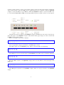
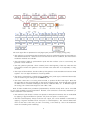
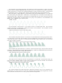
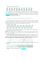
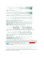
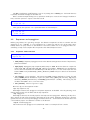
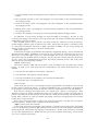
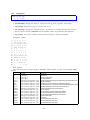
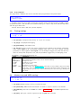
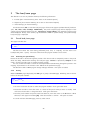
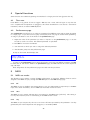
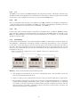
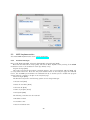
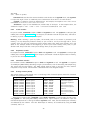
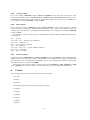
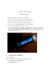
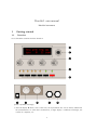
Shruthi-1 user manual
Mutable Instruments
1
Getting started
1.1
Overview
Let us familiarize ourselves with the Shruthi-1:
(Yours is probably not beige)
• The LCD display D shows, most of the time, the 4 parameters that can be directly edited with
the potentiometers. In some other circumstances, it might display a confirmation messages, the
content of a sequence, etc.
1
• The clickable encoder E can be used to navigate between parameters/pages, or to step through
the values of a parameter.
• The four potentiometers P modify synthesis parameters, in relation to the selection of parameters
shown on the display.
• The 8 LEDs L1...*L8* provide complementary information as to which editing page is active.
• The 6 switches S facilitate navigation between pages. The switches S1 to S4 are used to cycle
between groups of related pages ; S5 is used to switch between the synthesis pages and the
sequencer/system pages ; and S6 is used to bring the load/save page to save or recall a patch, a
sequence, or the system settings.
The following connectors are available on the rear panel:
• 1: 2.1mm DC power jack. The Shruthi-1 can be powered with a 7.5V-12V unregulated supply,
or with a 9V battery adapter. Make sure that the connector has a center pin (or tip) positive /
outer collar (or sleeve) negative pin polarity. Most universal power supplies allows the polarity to
be selected – the polarity being often represented by a diagram like this: - (o +, or by the indication
tip: +. The power supply has a reverse polarity protection and can handle voltages up to 15V.
Note that VCF/VCA boards distributed by third parties might not follow these specifications and
have different power supply requirements.
• 2: MIDI in. This input should be connected to the MIDI out port of a sound card, master keyboard,
sequencer...
• 3: MIDI out. This output can be used as a MIDI thru, but also to transmit the notes generated
by the Shruthi-1’s internal sequencer, backup data, or for polychaining units.
• 4: Line-level, mono audio output.
• 5: Line-level, mono audio input. Note that the external audio signal flows through the VCF and
the VCA - you won’t hear anything until a note or sequence is played by the Shruthi-1 to "open"
the VCA.
Depending on how you have assembled the analog board, a global power on/off switch and gain pots
for the audio input/output might be available too – on the rear panel, on the sides, or on the front panel.
1.2
Controls and navigation
1.2.1
Pages
The Shruthi-1 parameters are edited by blocks of four (one per potentiometer). A set of four related
parameters are grouped together on a page. For example, the Filter page will assign the four following
functions to the four potentiometers: filter cutoff, filter resonance, envelope->filter modulation, LFO>filter modulation. The LEDs L1 to L6 display the currently active page. Moreover, the LCD display is
constantly showing which knob does what in the current page. For example, if the filter page is active,
the display will show:
Cut res env lfo
110
0 10
0
The Shruthi-1 features 18 pages of parameters – hence the page/navigation is a bit more complex
than on its predecessor!
Just like on the Shruti, pages are bundled together in groups, and repeatedly pressing one of the
group switches cycles between the different pages in this group. But now, pages are also grouped into
two large categories: one category contains all the pages related to sound synthesis – the ones you’ll
2
navigate in when creating a sound – and another category contains all the pages related to sequencing
and to system settings. The switch S5 is used to toggle between the two categories. When the synthesis
category is active, the LED on top of S5 is lit. When the sequencer category is active, this LED is not
lit. The switches S1, S2, S3 and S4 cycle through different groups of pages as shown on this diagram:
The upper list shows the pages in the synthesis category accessible from each switch, the lower list
shows the pages in the sequencer category. L7 indicates which page category is active, and the leds
L1-L6 show which page is active.
Here’s an example. The Shruthi-1 displays:
Cut res env lfo
110
0 10
0
L7 is lit (synthesis category) and L3 is lit: the filter page is active.
Press S1 to jump into the oscillators group. L1 is lit, and the LCD is now displaying:
Sha prm rng sub
saw
0
0 tr1
Press S1 again to move to the next page in the oscillators group. L2 is now lit, the LCD is displaying:
Sha prm rng tun
squ 16 -12 12
Now press S7 to switch to the sequencer category. L7 is now off, L1 is lit. The active page is the
clock page:
Mod bpm gro amt
stp 120 swi
0
Press S7 again to get back to the synthesis category. L7 is on, and you are back to the oscillator
2 page.
3
1.2.2
Editing
When a page is active, a summary of the four parameters modified by each potentiometer is displayed
on screen. While tweaking a potentiometer, the full parameter name, its value, and the page name, are
temporarily displayed on the screen:
filter
cutoff
89
After a short delay, the four parameters page summary is shown again.
1.2.3
Using the encoder.
When the Shruthi-1 is displaying a page summary, the rotary encoder can be used to scroll through the
parameters. The name of the active parameter is capitalized. For example, resonance is here the active
parameter:
cut Res env lfo
110
0 10
0
Rotate the encoder clockwise to make env the active parameter, rotate the encoder counter-clockwise
to make cut the active parameter. If you continue rotating the encoder clockwise for several steps, the
next page, env 1, will be shown, and its first parameter, atk, will become selected. Once a parameter
is selected, click the encoder to edit it. The encoder is now used to increment/decrement the parameter
value. Once the value has been set, click on the encoder again to move back to the 4 parameter summary.
Note that potentiometer and encoder editing can be combined. For example, use a potentiometer to
quickly adjust a parameter, and then, while the parameter name is still displayed on the screen, use the
encoder to fine-tune it.
A last trick: if you hold S6 while rotating the encoder, it will increment/decrement by 10 instead of
1. This is particularly useful for browsing long lists of patches...
That’s all you need to know about the pages/navigation system!
2
Reference
The section describes one by one all the parameters accessible on the synthesis and sequencer pages.
2.1
Synthesis
Before digging into the pages details, here is a diagram of the Shruthi-1 signal flow.
4
The audio signal flow is represented in red (digital path) and then in orange (analog path):
• The oscillators 1 and 2 generate digital waveforms, which are combined together by the modulator.
The default modulator is a balance control over the level of the two oscillators, but more esoteric
modulation methods are available.
• The sub-oscillator (which is synchronized in pitch with the oscillator 1, but 1 octave lower) also
generates a basic waveform.
• The click generator generates a short transient/click at the beginning of the note. Note that the
sub-oscillator and the click generator cannot be used at the same time. It’s bassy-beefy or clicky,
not both.
• The output of the modulator, the sub-oscillator/click-generator and some additional noise are mixed
together. You can adjust the balance of each ingredient.
• The result is converted into a pseudo analog (10 MHz / 1bit) audio signal, and mixed "electrically"
with an external signal coming from the Audio in jack.
• The result is then sent to an analog VCF and VCA, to produce the final audio signal. Note that
the signal flow of this section depends on the signal processing board. Some boards might include
an additional CV-controlled waveshapper, FX section, additional filter, etc. at different stages of
the analog path. Some boards might not even offer a VCF.
Each of these modules have parameters (represented by the blue arrows) which can be controlled
by any of the modulation sources listed below. However, some connections are already "hardwired" (or
rather "softwired" in the firmware):
• The oscillators’ pitch always track the note played on the keyboard. However, this can be disabled
by applying a negative modulation (amount: -63) from note pitch to oscillator pitch.
• The filter cutoff frequency always tracks the note. Again, this can be disabled or attenuated by
applying a negative modulation from note pitch to cutoff frequency. The rationale behind this
choice is that most of the time, you want 1:1 tracking, so this frees up a slot in the modulation
matrix for something more interesting!
5
• Lfo 2 and Envelope 1 are always connected to the filter, their modulation amount being controlled
by dedicated parameters on the filter page.
The following routing programmed in the init patch:
Source
Lfo 1
Lfo 1
Lfo 2
Lfo 2
Lfo 2
Step sequencer
CV 1
CV 2
Envelope 2
Velocity
Bender
LFO
2.1.1
Destination
Oscillator 1 coarse pitch
Oscillator 2 coarse pitch
Oscillator 1 PWM
Oscillator 2 PWM
Oscillators balance
Oscillators balance
Oscillator 1 PWM
Oscillator 2 PWM
VCA gain
VCA gain
Oscillator 1+2 fine pitch
Oscillator 1+2 fine pitch (vibrato)
Amount
0
0
0
0
0
0
0
0
100%
25%
2 semitones
2 semitones
Oscillator 1
Sha prm rng sub
saw
0
0 sq1
• sha (shape): Oscillator 1 waveform shape.
• prm (parameter): Oscillator 1 parameter. This changes the timbre of the generated waveform,
in a waveform-specific way (see below).
• rng (range): Oscillator 1 pitch, from -24 semitones to 24 semitones (relative the pitch of the
MIDI note).
• sub (subosc): Sub-oscillator shape (see below).
The following is a list of all the available waveforms, with some applications and a description of what
adjusting the parameter setting actually does.
none: Silence
This simply switches off the oscillator. This might be useful for filtering/gating external signals, or
to temporarily mute an oscillator when editing a patch.
saw: Sawtooth
This waveform is perfect for basses and brass sounds. The parameter controls the waveshapping when its value is increased, an increasingly large section of the waveform is shifted up. Note that this
is not intended to be a perfect, drawn with a ruler, sawtooth. It contains a bit of high-pass filtering to
make it sound more Juno-y. This waveform is band-limited. Thus, only a limited amount of aliasing
artifacts will be heard when playing high-pitched notes.
square: Square wave
6
The parameter controls the pulse-width. This waveform is perfect for simulating a clarinet, for basses,
"hollow" sounds or Depeche Mode-like leads. Note that this is not intended to be a perfect, drawn with
a ruler, square wave. It contains a bit of high-pass filtering to make it sound more Juno-y. This waveform
is band-limited and only a limited amount aliasing will be heard when playing high-pitched notes.
Note that there’s a slight difference in sound when moving the parameter from 0 to 1. To offer the
best sound quality, the pulse width = 50% flavor is read straight from a wavetable at full sample rate,
while the pulse width > 50% flavor is obtained from two dephased sawtooth waves, evaluated at half the
sample rate. For bass sounds, for which aliasing is not going to be a problem, it is recommended to use
pwm instead of square to get a beefier sound.
triang: Triangle
A pure waveform, which serves as a good basis for flute or soundchip-like leads. The parameter
controls some kind of waveshapping, clipping the bottom of the waveform. This waveform is bandlimited and will still sound fine above C5.
zsaw: Phase-distortion sawtooth with filter sweep
This waveform uses phase distortion to recreate a low-pass filtered sawtooth by progressively "pinching" the phase of a sine wave. The parameter controls the brightness of the sound: from a sine wave to
a sawtooth, then from a sawtooth to a sawtooth gone through an ugly transistor amp. Good for dirty
bass guitar sounds or clavinets.
zreso: Phase-distortion sawtooth with resonant filter sweep
This waveform uses phase distortion to recreate a sawtooth sent through a low-pass filter with high
resonance. The parameter controls the resonance frequency. Useful for doubly-filtered sounds, formants,
or anything where its synthetic, cheesy, feel will shine.
ztri: Phase-distortion resonant triangle monster
This thing is hard to describe and must be experienced. It sounds like a resonant filter sweep, but
has a very hollow, synthetic quality. It may or may not have been in the Casio CZ-101. This waveform
is likely to result in whacky sounds, vaguely evoking hardsync.
zpulse: Phase-distortion trapezoidal creature
Yet another waveform that makes little sense. When the parameter is set to 0, it sounds like a fat
superposition of a square wave and a sawtooth. Sweeping the parameter value progressively increases
what sounds like the resonance of an odd, goofily saturated analogue filter.
7
zsync: Phase-distortion/self-sync trick
You know the trick: one oscillator playing a low-frequency square wave and another oscillator a
higher-frequency sine wave, the first one resetting the phase of the second... and the two of them sent
into a ring-modulator! Now roll this into one single sound generator, the parameter of which controls
the frequency ratio of the two oscillators: we call it zsync... The resulting sound is close to a Jew’s harp
or Morsing - band-passey and formantey.
pad: Stack of 4 detuned sawtooth waves
As the name implies, this waveform made of four stacked sawtooth waves is useful for pads (when
a copious amount of filtering is applied) or for harsh trance leads. The parameter controls the amount
of detuning between the four waves. Note that no bandlimiting is happening here, so this thing doesn’t
sound quite good above C5... but it’s doing a perfect job in the bass range!
fm: Minimal 2-operators FM
The parameter controls the modulation strength. This oscillator provides the base material for metallic
sounds, bells, metallophones, or the next 386 DX hit.
Warning When the fm oscillator is selected, the range parameter plays a slightly different role than
usual: instead of controlling the main pitch of the note, it controls the modulator frequency, and has a
drastic impact on the timbre.
waves, tampur, digitl, metall, bowed, slap, organ, male: wavetables, wavetables, wavetables!
All these waveforms are wavetables, comprising 16 single-cycle waveforms. The parameter scans the
wavetable, smoothly interpolating between each waveform. Some of these tables are "transwaves": the
single cycle waveforms were extracted from different "stages" of a sample, and you can somehow recreate
the original sample by using an envelope that will sweep the parameter from 0 to 127.
waves are 16 basic waveforms, or rather two series of 8 basic waveforms: waveforms 9-16 are one
octave higher.
tampur is a transwave extracted from a looped Tampura note.
8
digitl is a PPG-wave classic.
metall is made from single cycle waveforms extracted from classic D50 patches.
bowed is a transwave extracted from cello sounds.
slap is a transwave extracted from an SQ-80 slap bass patch.
organ contains 16 different mixtures of pure tones, ready for some "Light my fire" action.
male is another PPG-wave classic, it sounds vaguely like a human male voice.
user: user wavetable
This wavetable has two peculiarities: it is smaller than the other ones (8 single cycle waveforms, each
of them being 129 samples long), and it resides in RAM instead of residing in flash ROM. By default,
it is loaded with the same content as digitl, but its content can be altered by SysEx messages You can
find here some examples of MIDI files containing user wavetables.
Note that an extra set of 9 wavetables have been added at the end of the waveforms list.
8bits: bitwise anarchy
A palette of 8-bits sounding waveforms obtained by applying bitwise operations to a basic sawtooth
wave (something now known as "biscuiting").
9
crush: bit-crushed sine and triangle wave
From 0-63, this oscillator will produce a bit-crushed sine wave ; 63 corresponding to the maximum
amount of decimation. From 64-127, this will produce a bit-crushed triangle wave, 64 corresponding to
the maximum amount of decimation. As a result, the transition from the two waveforms is smooth since
the bit-crushing is very heavy when the two ends meet. A parameter value near 120 yields a very typical
NES bass sound.
pwm: my first Arduino synth
This waveform is a shamelessly naive square wave. The parameter controls the pulse-width. Contrary
to square, this waveform stinks aliasing - but for notes below C2 it is not a real problem: it becomes
much more aggressive and "in your face" than square.
noise: Filtered noise generator
The parameter controls the frequency of a simple 1-pole low-pass/high-pass filter in which is sent
white noise. From 0 to 63, high-frequency content is progressively added. From 63 to 127, low-frequency
content is progressively removed. Perfect as a raw material for percussions or sound effects.
vowel: Low-tech formant synthesis
Changing the parameter will sweep between different vocal-like sounds (14 vowels and 2 consonants).
Now. Spell. Daftpunk.
That’s it for the oscillators waveforms. Oscillator 1 is linked to a sub-oscillator / transient generator.
The first 6 settings correspond to the sub-oscillator, which is an oscillator of its own, playing always one
or two octave lower than the oscillator 1. The next settings disable the sub-oscillator and enable various
transient generators, which will produce a short, clicky sound at the beginning of the note:
• sq1 square sub-oscillator, 1 octave below osc. 1
• tr1 triangle sub-oscillator, 1 octave below osc. 1
• pl1 25% pulse sub-oscillator, 1 octave below osc. 1
• sq2 square sub-oscillator, 2 octaves below osc. 1
• tr2 triangle sub-oscillator, 2 octaves below osc. 1
• pl2 25% pulse sub-oscillator, 2 octaves below osc. 1
• click produces a discrete click (more obvious on sine/organ sounds).
• glitch produces a sound similar to that of a skipping CD.
10
• blow is a burst of noise with a slow attack.
• metal adds a metallic sounding, high-pitched click.
• pop adds a low-pitched discontinuity.
The transient generator can be used for instance to add some punch to metallic-sounding or FM
sounds, or for percussive effects.
2.1.2
Oscillator 2
Sha prm rng tun
saw
0
0
0
• sha (shape): Oscillator 2 waveform shape. The available waveforms are the same as for oscillator
1.
• prm (parameter): Oscillator 2 parameter.
• rng (range): Oscillator 2 pitch transposition, from -24 semitones to 24 semitones.
• tun (detune): Fine detuning of Oscillator 2.
2.1.3
Mixer
Op. mix sub noi
sum 32
0
0
• op (operator): Modulation operator (see below).
•
mix (osc bal): Oscillator 1/2 balance. Might do something different than balance when an
operator different from sum is selected (see the Oscillator 1 section).
• sub (sub osc.): Sub oscillator or transient generator level.
• noi (noise): Noise level.
The operator parameter controls how oscillator 1 and oscillator 2 are blended together. The different
modulation modes are:
11
Operator
sum
sync
ring
xor
fuzz
»4
»8
fold
bits
duo
2steps
4steps
8steps
seqmix
Description
Mixing
Mixing and synchronization: oscillator 2’s
phase is reset whenever oscillator 1’s phase is
reset. You won’t hear the detuning, but instead
a timbral modulation
Ring modulation - oscillators’ signals are scaled
and multiplied
XOR modulation. The bits of oscillator 1 and
2’s digital values are exclusive-or’ed, and the
result is shifted
Fuzz. Oscillator 1 and 2 are equally mixed and
sent to a waveshapper with a warm tanh response
Oscillator 1 and 2 are mixed and sent through
a dirty 4x sample rate reduction
Oscillator 1 and 2 are mixed and sent through
a dirty 8x sample rate reduction
Oscillator 1 and 2 are mixed and sent through
a foldback distortion
Oscillator 1 and 2 are mixed and sent through
a bit depth reducer
Duophony
Oscillator 1 / 2 cycling
Sound source cycling
Sound source cycling
Sound source cycling
What does the mix parameter do?
Adjusts the oscillator 1/2 balance
Adjusts the oscillator 1/2 balance
Balance between the original sound and the
output of the modulator
Shifts the output, with overflow
Fuzz amount
Oscillator 1/2 balance
Oscillator 1/2 balance
Distortion amount
Bit depth reduction amount
Adjusts the oscillator 1/2 balance
-
A few words about the last fancy modulation modes...
In duophony mode, you can play two-note chords (or bass + melody). The first note of the chord
will be assigned to oscillator 1, and the second note will be assigned to oscillator 2, like on the ARP
Odyssey or the Polivoks. This works best when mix is set to 32 and when oscillator 1 and 2 are set to
the same settings (otherwise small differences in timing can result in drastic changes as both notes of the
chord will be assigned to different oscillators). If you play more than 2 notes, the least recently played
note will be assigned to oscillator 2, the most recently played note to oscillator 1 ; and the other notes are
ignored. The sub-oscillator follows the least recently played note. Note that the Shruthi-1 is by design
a monosynth, with one set of envelopes & LFOs, and one filter / VCA - both notes will go through the
same filter and have the same envelope, resulting in a kind of weird paraphonic effect. Don’t be surprised
if you encounter pitch jumps, envelope clicks, weird voicing, or if things do not sound and feel as good
as on a polysynth - all these are due to stubbornly trying to fit duophony into an essentially monophonic
design. Ironically, the duophony mode works best with the arpeggiator - it will move through the chord
in pairs of notes. Try it!
In 2steps mode, oscillator 1 and oscillator 2 are alternatively on and off at each new note.
In 4steps mode, oscillator 1, oscillator 2, the sub oscillator and the noise source are alternatively on
and off at each new note. The first note you play is played by the sub-oscillator ; the second note by
oscillator 1 ; the third by the noise source ; the fourth by oscillator 2. Try this with the arpeggiator and
you get a mini drum pattern! 8steps does the same thing, but with a more complex cha-cha rhythmic
pattern.
Finally, in seqmix mode, the on/off status of the oscillators / sub / noise is controlled by the values
in the step sequencer. 1 = osc 1 ; 2 = osc 2 ; 4 = sub ; 8 = noise ; and these values can be added up
for combinations (osc 1 + noise = 1 + 8 = 9). The following table enumerates all combinations:
12
Step sequencer value
0
1
2
3
4
5
6
7
8
9
a
b
c
d
e
f
Osc 1
X
X
X
X
X
X
X
X
Osc 2
X
X
X
X
X
X
X
X
Sub
X
X
X
X
X
X
X
X
Noise
X
X
X
X
X
X
X
X
You can thus use this mode for programming simple drum patterns in the step sequencer - using the
sub oscillator as a bass drum and the noise as a snare drum, and interweaving notes from the oscillators
between the drum notes.
2.1.4
Filter
Cut res env lfo
66
0 16 37
• cut (cutoff): Filter cutoff frequency.
• res (resonance): Filter resonance.
• env (env1->vcf): Modulation amount from envelope 1 to VCF. If you want to set a negative
modulation amount, you can patch env1 to the VCF in the modulations section and ignore this
parameter.
• lfo (lfo2->vcf): Modulation amount from LFO 2 to VCF. Again, if you want to set a negative
modulation amount, you can patch the LFO 2 to the VCF in the modulations section and ignore
this parameter.
2.1.5
Envelope 1 / 2
Atk dec sus rel
0 44 20 60
• atk (attack): Envelope attack time.
• dec (decay): Envelope decay time.
• sus (sustain): Envelope sustain level.
• rel (release): Envelope release time.
The predecessor of the Shruthi-1 used linear envelopes. The envelopes are now piecewise linear with
a "knee", to capture the feeling of exponential envelopes (the same trick was used on the SID).
13
2.1.6
LFO 1 / 2
Sha rat atk mod
tri 52
0 fre
• sha (shape): LFO waveform. The available LFO waveforms are: triangle, square, sample&hold,
ramp (sawtooth), step (cycles through the sequence of values programmed in the step sequencer).
16 additional waveforms named 1 to 16 are also available. They are directly taken from one of
the wavetables, are intended to be used with slow frequencies, and are very good at mimicking the
sounds of machines or... human organs.
• rat (rate): LFO rate.
• atk (attack): LFO rise time. When this setting is non-zero, the LFO will take some amount of
time to reach its maximum amplitude
• mod: LFO synchronization mode: when set to free, the LFO is free-running. When set to slave,
the phase of the LFO is reset every time a new note is played. Finally, when set to master, the
LFO will retrigger the envelope (LFO 1 retriggers envelope 1 and LFO 2 envelope 2).
Among the choices of LFO rates, the first values, which are prefixed by a "x", are tempo-synchronized
settings. The number following the X corresponds to the number of sequencer steps that will be used to
set up the LFO period: x16 simply means that the LFO will go through one cycle over the duration of
16 sequencer steps (4 beats). For example, if you set the LFO to a ramp, with a rate of x4, and map it
to the cutoff, the cutoff will raise over the duration of a beat and return to a low value at the beginning
of each beat. With a x2 or x1 rate, square LFO mapped to the VCA, you can get old-school trancey
gater effects. With a x2 rate, sample&hold LFO mapped to the cutoff and the basic arpeggiator pattern,
with high resonance, you get a random bleeping at every note.
2.1.7
Modulation matrix
In this page, the routing between the modulation sources and destinations is configured. The first
important thing about this page is that it works a bit differently from the others: the potentiometer P1
is used to select a patchcord, while P2, P3 and P4 are used to edit it.
Here is an example:
Mod src dst amt
1 lf1 ~1
0
This page means: "The patchcord #1 connects the LFO1 to the oscillator 1 pitch, and the corresponding modulation amount is set to 0". By turning the first knob, you can scroll through the different
connections in place, for example:
mod src dst amt
9 en2 vca 63
"The patchcord #9 connects the envelope 2 to the VCA gain, and the corresponding modulation
amount is 63".
Once a patchcord is selected with the first knob, the source/destination/amount are edited with the
3 other knobs. Note that you can see in details the source and destination when tweaking one of those
parameters:
14
mod en2>vca
amount
62
When editing modulations, L6 blinks/is dimmed to reflect the value of the selected modulation source.
The modulation sources are, in modern lovers precise order:
1. lfo1, lfo2: LFO output (centered).
2. stpseq: Step sequencer output.
3. stpsq1: Step sequencer’s little brother 1: it cycles on the first 8 steps of the sequence.
4. stpsq2: Step sequencer’s little brother 2: it cycles on the last 8 steps of the sequence.
5. arp: Rhythmic gate signal, which outputs a high value when the arpeggiator or sequencer contains
a note at the current step, or 0 when there is no note.
6. mwheel: Modulation wheel value read from the MIDI input.
7. afttch: Aftertouch value read from the MIDI input.
8. bender: Pitch-bend controller value read from the MIDI input (centered).
9. offset: A boring constant value. This is useful if you want to output a fixed value to one of the
CV outs.
10. cv1, cv2, cv3, cv4: Control voltages read from the CV input pins. By default, the input pins are
floating, so it’s likely that these modulation sources will sound just like noise.
11. cc A, cc B, cc C, cc D: Value of the Control Change 16, 17, 18 and 19.
12. noise: Another noise generator! Mapped to the VCA, makes for some super snares!
13. env1, env2: Envelopes.
14. velo: Note velocity.
15. random: A random value updated every time a new note is played.
16. note: Pitch of the currently played note (centered).
17. gate: Keyboard gate signal, null when no key is currently pressed.
18. audio: Digital audio signal produced by the mixer. Please note that since the modulation matrix
is recomputed at 976Hz, some serious aliasing is happening here. You’re not going to do FM with
this thing, most of the time it sounds like crap, but it’s something fun to experiment with!
19. op. 1: Operator 1.
20. op. 2: Operator 2.
21. trg 1: Trigger 1.
22. trg 2: Trigger 2.
The modulation destinations are, in modern lovers precise order:
1. cutoff: Filter cutoff.
2. vca: VCA gain.
15
3. pwm1: Oscillator 1 parameter (can be pulse width, but also waveshapping, phoneme, etc. depending on the oscillator type).
4. pwm2: Oscillator 2 parameter (can be pulse width, but also waveshapping, phoneme, etc. depending on the oscillator type).
5. osc1: Coarse oscillator 1 pitch, in a -16 / 16 semitones range. Also affects the sub-oscillator’s
pitch.
6. osc2: Coarse oscillator 2 pitch, in a -16 / 16 semitones range..
7. osc1+osc2: Coupled oscillator 1+2 pitch, in a -4 / 4 semitones range. Also affects the suboscillator’s pitch.
8. fine: Fine oscillator 1+2 pitch, in a -1 / 1 semitones range. Also affects the sub-oscillator’s pitch.
9. mix: Oscillator 1/2 balance (or whatever the modulator does with the balance parameter).
10. noise: Noise volume.
11. subosc: Sub-oscillator volume.
12. reso: Filter resonance.
13. cv1: Control signal for the CV output #1.
14. cv2: Control signal for the CV output #2.
15. attack: Envelope 1 and 2 attack speed. For example, map velocity to this modulation destination
to have a faster attack time on notes played with a high velocity.
16. lfo1, lfo2: Frequency modulation of the two LFOs.
17. env1, env2: Envelope 1 and 2 triggers. Whenever the modulation source goes up, the envelope
is retriggered.
One thing that requires a bit of clarification is the notion of "centered" modulation source. Let’s take
an example. We have a triangle LFO mapped to the filter cutoff, with a modulation amount of 30. If
the cutoff is set to 80, the actual value of the cutoff will oscillate between 50 (80-30) and 110 (80+30).
On the other hand, if we have an envelope mapped to the cutoff with a modulation amount of 20, the
cutoff will go from 80 to 120 (80 + 2 * 20), then down to 80 after the release. This is something to
remember if you want to do PWM, for example. If you set the PWM modulation amount to 40, you also
have to set the oscillator pulse width value to 40, so it will oscillates between 40-40 = 0 and 40+40=80.
Otherwise, it will spend half of the time stuck at 0. But this makes things nicer for vibrato, tremolo,
wah-wah or growl effects!
16
Important Quirk ahoy!
The modulation amount of the last patch cord is adjusted by the modwheel. Huh? Let’s say you set
patch cord 12 to go from LFO 1 to the oscillators fine pitch with an amount of 16:
Mod src dst amt
12 lf1
~ 16
This modulation will be applied with an amount proportional to the modwheel position - by default
it won’t be active until you start moving the modulation wheel, and to get it at full strength, you’ll have
to push the modulation wheel to the max.
2.1.8
Operators
Press the modulation matrix button twice to bring the operators page. In this page, you can configure
the two "operators". An operator takes 2 modulation sources, applies a fancy (or not) mathematical
operation on them, and the result is made available as a new modulation source in the modulation matrix.
Op. in1 in2 out
1 lf1 lf2 add
Use the first setting (*op.*) to select which operator to modify. The second and third options allows
you to select which modulation destination you want to operate on. The last setting is the operation to
apply:
• add adds the values of two modulation sources.
• prd computes the product of the two modulation sources.
• max takes the maximum of the two sources.
• min takes the minimum of the two sources.
• xor totally messes up the two sources.
• >= outputs a large value if source 1 is above soure 2, 0 otherwise.
• <= outputs a large value if source 1 is below soure 2, 0 otherwise.
• qtz source 1 is quantized into a number of values set up by source 2.
• lag source 1 is low-pass filtered, with a cutoff frequency set up by source 2.
There are plenty of things to experiment with... Create a multi-stage envelope by taking the max
of envelope 1 and 2 ; mask a LFO by the step sequencer ; build a chaotic LFO using feedback and xor
modulation between the two LFOs ; Square the value of a LFO to change its shape...
Here is a more precise example showing how to low-pass filter a square LFO to create a "soft"
modulation source routed to the filter. First, route the operator 1 output to the filter cutoff:
Mod src dst amt
1 op1 cut 63
Then, specify that operator 1 is LFO1 transformed by a "lag processor".
Op. in1 in2 out
1 lf1 =4 lag
17
The in2 is the filtering cutoff frequency. You can try setting this to velocity too: the harder the note
is pressed, the harder the edges of the LFO are!
Here is another example showing how to quantize an envelope to create a low-fi "steppy" modulation.
First, route the operator 1 output to the filter cutoff:
Mod src dst amt
1 op1 cut 63
Then, specify that operator 1 is a quantized version of the envelope 1:
Op. in1 in2 out
1 en1 =4 qtz
2.2
Sequencer and arpeggiator
Before going further, let’s get things straight: the Shruthi-1 sequencer has little in common with the
sequencer of, say, a TB-303: it is not intended to be a "press play and let it do all the work" thing.
Indeed, there’s no "play" button on the Shruthi-1! You have to think of it as an arpeggiator-like tool something to help create complex riffs and patterns with limited keyboard action.
2.2.1
Sequencer mode and clock
Mod bpm gro amt
stp 120 swi
0
• mod (mode): Sequencer/arpeggiator mode. This deserves some generous amount of explanations,
please read further!
• bpm (bpm): Arpeggiator/step sequencer/LFOs tempo in BPM. Note that there are 8 super fast
values (270, 300, 330, 360, 420, 480, 600, 720) for sound effects. extern will sync the Shruthi-1
clock to the ticks received from the MIDI input. x2 ext will sync to a clock twice faster than the
external MIDI clock (double BPM). /2 ext, /4 ext and /8 ext will sync to divisors of the external
MIDI clock.
• gro (groove): groove template. The options are swing (uneven distribution of pairs of 1/8th
notes), shuffle (uneven distribution of pairs of 1/16th notes), push (push the beat), lag (sloppy
drummer!), human (humanization) and monkey (humanization + shuffle). This setting only has
an effect when amt is set to a non-zero value.
• amt (amount): amount of groove to apply.
Now let’s dig into the sequencer modes...
stp: step sequencer only
When stp is selected, the arpeggiator and pattern sequencer are disabled. The only pulsating, modulating things running are the LFOs and the step sequencer.
arp: arpeggiator
When arp is selected, the chords played on the keyboard are arpeggiated. Releasing the keys for a
short amount of time stops the arpeggio but keeps the clock ticking. Releasing the keys for a duration
greater than that of a bar stops the arpeggio and resets the clock – it will restart from the first beat once
a chord will be played – this behavior is similar to the Shruti-1.
arp+lt: latched arpeggiator
This mode starts the arpeggiator in latched mode. Here is an example of how it works:
18
1. Press C4 and keep it held: the arpeggiator starts and plays C4 on the programmed rhythmic/arpeggio
pattern.
2. Now, press E4 and keep it held: the arpeggiator now plays C4/E4 on the programmed rhythmic/arpeggio pattern.
3. Press G4 and keep it held: the arpeggiator now plays C4/E4/G4 on the programmed rhythmic/arpeggio pattern.
4. Release those 3 keys: the arpeggiator continues playing C4/E4/G4 on the programmed rhythmic/arpeggio pattern.
5. Press F4: the arpeggiator now plays F4 on the programmed rhythmic/arpeggio pattern.
To summarize: as long as keys are held, new notes are added to the arpeggio. As soon as a key
is released, the arpeggio will continue to loop the pattern but will "forget" whichever keys were being
pressed when a new note is played.
Now, the $1M question: how to tell this crazy thing to shut up? There are two ways of stopping a
latched arpeggio sequence, both of them kind of violent: kicking the hold pedal, or punching 8 notes
at a time (use your knuckles, left hand on CDEF, right hand on GABC). Or you can just change the
sequencer mode to another setting to leave the latched mode.
seq: pattern player
In this mode, the pattern programmed in the sequencer is triggered by playing a note on the keyboard
(Roland calls this "RPS"). Depending on the note you play, the pattern is transposed: play C4 to play
the pattern as recorded, C#4 to play it one semi-tone higher, B3 to play it one semi-tone lower, etc.
The pattern will stop whenever the key is released – but the clock will continue ticking for the duration
of a bar - and if a key is pressed during this interval, the pattern will resume in time. This mode is most
useful for playing and transposing a bassline.
seq+lt: pattern player
This mode is similar to seq, with one exception: when you release a key, the pattern will continue
playing. To make it stop, press again the note corresponding to the current transposition level. For
example:
1. You press C4: the sequence starts without transposition.
2. You release C4: the sequence continues playing.
3. You press and release G4: the sequence is now played one fifth higher.
4. You press G4 again: the sequence stops.
rec: bar looper
In this mode, play any note to start playing the pattern programmed in the sequencer. This note will
become a kind of "start/stop" button – it is thus recommended to pick a note unlikely to be played later
in the sequence you’ll record (I usually use the first or last key of the keyboard to start the sequence).
Once this key is pressed, the pattern plays at its original pitch – there’s no transposition. Then,
whenever a new key is pressed, the Shruthi-1 jumps into recording mode and starts recording what is
played on the keyboard for the duration of 1-bar. Beware: chords are not recorded, and quantization is
severe! After a duration of 1 bar has elapsed, the Shruthi-1 leaves the recording mode and continues
looping what was just recorded.
How to stop? Once the pattern is playing, play again the "start/stop" note (the one you picked to
start the sequence). Another option is simply to kick the hold pedal.
impro: pattern player with overrides
In this mode, the pattern programmed in the sequencer is started/transposed by playing and holding
a note on the keyboard, just like in seq. While this note is held, any new note played on the keyboard
will be played and override what was originally in the sequencer - allowing some variations to be played
on top of the sequenced pattern. Release the first note to stop the pattern from playing, or play another
root note to transpose the pattern.
19
2.2.2
Arpeggiator
Dir rng pat wrp
?
1
0 gla
• dir (direction): Arpeggiator direction. The options are up, down, up/down, and random.
• rng (range): Arpeggiator range, in octaves, from 1 to 4.
• pat (pattern): Arpeggiator rhythmic pattern. 15 patterns are available (see the chart below).
The last option in the list, sequence uses the rhythmic pattern programmed in the sequencer.
• wrp (warp): This option modifies in which order the steps of a sequence are played.
Arpeggiator patterns
1:
2:
3:
4:
5:
6:
7:
8:
9:
10:
11:
12:
13:
14:
15:
o o o o o o o o
ooo ooo ooo ooo
o o ooooo o oooo
o o oo oo o oo o
oooo oo oooo oo
o o
o o
o o o o o o
o o o o o o
o o o o o o
oo oo oooo oo oo
ooooo oo oo ooo
o
o
o o o o
o oo
o o o oo
o
oooooo oo
o
o
o oo
Warp patterns
This table shows how a 8-steps sequence, 01234567, will be warped, for each of the available warp
settings:
Name
->
<-> - <-> <glass
krama
jata
sikha
ghana
2glass
2krama
2jata
2sikha
2ghana
4glass
4krama
4jata
4sikha
4ghana
Description
Forward
Backwards
Ping-pong 1
Ping-pong 2
Philip glass augmentation,
Vedic recitation pattern 1,
Vedic recitation pattern 2,
Vedic recitation pattern 3,
Vedic recitation pattern 4,
Philip glass augmentation,
Vedic recitation pattern 1,
Vedic recitation pattern 2,
Vedic recitation pattern 3,
Vedic recitation pattern 4,
Philip glass augmentation,
Vedic recitation pattern 1,
Vedic recitation pattern 2,
Vedic recitation pattern 3,
Vedic recitation pattern 4,
1/16
1/16
1/16
1/16
1/16
1/8
1/8
1/8
1/8
1/8
1/4
1/4
1/4
1/4
1/4
Result
01234567
76543210
0123456776543210
01234567654321
0010120123012340123450123456012345671234567234567345...
01122334455667
011001122112233223344334455445566556677667
012210012123321123234432234345543345456654456567765567
0110012210012122112332112323322344322343...
01012301234501234567234567456767
012323454567
012323010123234545232345456767454567
012345452301012345234567674523234567
012323010123454523010123452345452323...
0123012345674567
01234567
012301234567012345674567
012345674567012301234567
012345674567012301234567
20
2.2.3
Pattern editor
The pattern editor page is very different from the other pages. Here is how it looks like:
|00| C3 - 7 0 |
>|01| C3 - 7 0 |
It contains 5 columns, showing, from left to right:
1. The step number
2. The note at this step
3. The rhythmic event at this step: note (represented by a note icon), tie/slide (represented by a –
sign), or rest (empty)
4. The velocity (applies only to steps with a note)
5. The step sequencer/controller value at this step, from 0 to 15 (values from 10 to 15 are represented
by the letters a to f)
The pattern can be edited with the potentiometers. P1 scrolls through the steps, P2 changes the
note at the current step. P3 changes the rhythmic event and velocity value at the current step. Finally,
P4 modifies the controller value.
The encoder can be used to scroll through the steps. Clicking the encoder enters the edit mode: a
blinking cursor is shown, and the encoder is now used to increase/decrease the note value. Clicking the
encoder again leaves the edit mode.
While in edit mode, pressing a key on the MIDI keyboard will record the note number at the current
step, and move to the next step. This can be seen as a naive "step by step recording" mode, which can
be used while a sequence is playing.
Three important notes:
• The pattern length is by default 16 steps, but this can be changed on the Rhythmic sequencer
or Step sequencer pages.
• The note sequence, rhythmic pattern, and controller (steps) sequence all have the same length.
• The step sequence (controller values) have an effect only when the step sequencer is routed to a
modulation destination in the modulation matrix!
2.2.4
Rhythmic sequencer
This page shows, on a single screen, the rhythmic content of the bar programmed in the pattern editor.
It is particularly useful when programming a rhythmic pattern for the arpeggiator - a task for which the
only information that really matter are the note velocities and rhythmic events.
The first line of the screen shows the rhythmic events, the second line the programmed velocities:
xxx x x x---x--777 7 6 54443111
Use P2 to move the cursor, P3 to change the rhythmic event/velocity at the selected step, and P4
to adjust the pattern duration. The encoder can be used for editing too: select a step, click, edit the
step value, and click again when done.
21
2.2.5
Step sequencer
This page shows a different view of the controller values programmed in the pattern editor.
step sequencer
0000ffffcccc4444
Use P2 to move the cursor, P3 to change the controller value at the selected step, and P4 to adjust
the pattern duration. The encoder can be used for editing too: select a step, click, edit the step value,
and click again when done.
P1 can also be used to shift and cycle the sequence.
2.3
Tuning settings
Oct rag prt leg
0 equ
0 off
• oct (octave): Transpose every note by -2, -1, 0, 1 or 2 octaves.
• rag (raga): Scale/keyboard mapping.
• prt (portamento): Portamento time.
• leg (legato): Legato on/off. This option specifies how the Shruthi-1 will interpret overlapping
notes. When legato is off, the envelope retriggers every time a new note is played, and the
portamento is always applied. When legato is on, the envelope retriggers only when the new note
does not overlap with the previous one, and the portamento triggers only on overlapping notes.
The different scales/keyboard mappings are:
Name
equal
just
pythagorean
1/4 eb
1/4 e
1/4 ea
bhaira ... rasia
2.4
Description
Equal temperament
Just intonation (frequency ratios to C are rational numbers)
Pythagorean scale
E and B are 1/4 tone lower
E is 1/4 tone lower
E and A are 1/4 tone lower
A bunch of ragas of the Maihar gharana . Note that it is not possible to play notes outside
of the raga - if you attempt to do so, the previously played note will be retriggered. The
suggested mode of operation is to find out which keys are active in the raga, and improvise
with them!
Master tune and MIDI settings
Tun chn mid spl
0
1 ful C4
• tun (tune): Master tuning in the -1/+1 semitone range.
• chn (midi chan): MIDI channel the Shruthi-1 is tuned to. Use 0 to receive on all channels.
• mid (midi out): Data sent to the MIDI out. Refer to this paragraph from the MIDI implementation
section.
• spl (split): Split point. Used in conjunction with the split midi out mode.
22
2.5
System settings
Pau sna fil cv.
8 off lpf 4cv
• pau (pause): Duration (in increments of 0.128 seconds) during which the long parameter name
and value is shown on screen when a potentiometer is adjusted. When set to 0, the screen always
shows the four parameters summary.
• sna (snap): Enables potentiometers’ "snap" mode. This mode makes it less likely to accidentally
change a parameter value when switching pages. Suppose you’re tweaking the filter resonance with
P2 – you rotate it all the way down to 0. Then you switch to the oscillator 1 page to adjust the
oscillator 2 parameter. If the current value of the parameter is set to 64, you’ll hear a discontinuity,
since the value of the parameter will instantly jump to 0 or 1 when you start touching the pot.
When snap is on, things will happen differently: rotating the pot will have no effect until the
position of the pot actually reflects the current value of the parameter. After that, the parameter
value will track the potentiometer’s position. Another way to explain it: when snap is on you have
to move the pot to "grab" the current parameter value before the parameter is modified.
• fil (filter): Enables software extensions for a specific filter board. The default, lpf must be selected
for the CEM3379, SMR4 and IR3109 filter boards. ssm must be selected for the SSM2044 filter
board. What does it do? It enables a second filter page (press S2 twice to bring it) in which you
can control the HPF frequency.
• cv. (cv.mode): Enables software handling of specific input devices connected to the CV inputs.
4 cv in is the default: the 4 voltages at the 4 CV ins are read and made available in the modulation
matrix. prgm must be selected to enable Frank Daniels’ programmer. pedals directly map CV1
and CV2 to oscillator 1 and 2’s parameter, and CV3 to the cutoff frequency. It has been used for
a custom-built Shruthi with an expression pedal connector and a joystick...
2.6
Ch1
1
Trigger events
n1 ch2 n2
36
1 38
This page allows two notes to be defined as trigger events. In the example above, MIDI notes 36 and
38 on channel 1 are used as triggers. Any combination of note / MIDI channel can be used.
When a note on message matching the trigger definition is received, the Shruthi-1 does not emit
any sound. Instead, it sets to its maximum value the trg 1 or trg 2 modulation source.
When a note off message matching the trigger definition is received, the Shruthi-1 does not interrupt
any sound. Instead, it sets to its minimum value the trg 1 or trg 2 modulation source.
Depending on which destination the trg 1 and trg 2 sources are patched to, this can for example be
used to:
• Retrigger an envelope every time the trigger event note is played (destination = envelope)
• Modify the rate of an LFO for dubsteppy effects (destination = lfo rate)
• Simulate a snare drum hit by increase the volume of the noise source (destination = noise mix
level)
As for the trigger event themselves, you can send them from a sequencer (probably from a channel
different from the one the Shruthi-1 is played), a MIDI foot controller, or just set them to be two keys
of your keyboard (for example the lowest C and D).
23
3
The load/save page
The Shruthi-1 can save in persistent memory the following information:
1. Patches (16 in internal memory, 64 or more on the external eeprom)
2. Sequences (16 in internal memory, 64 or more on the external eeprom)
3. Global settings (in internal memory)
Use the last switch, S6, to enter the load/save page. If the current page is synthesis-related (*oscillator
1/2*, mix, filter, LFO, envelope, modulations), the patch load/save page will be displayed. If the
current page is sequencer-related (*clock*, arpeggiator, pattern editors), the sequence load/save page
will be displayed. Finally, if the current page was related to MIDI or system settings, the system settings
load/save page is displayed.
3.1
Patch load/save page
This page looks like this:
browse :patch
1 init
The first line shows the action being performed (load, save, or compare), and the item to be
loaded/saved (here: a patch). The second line shows the program number and its name.
3.1.1
Browsing the patch library
Rotate the encoder to browse through the patches. Click the encoder to temporarily revert to the patch
which was being edited before entering the load/save page: browse is replaced by compare on the
screen. Click the encoder again to resume browsing patches.
You can use the four knobs to tweak the sound parameters while browsing through the patches. The
mapping of parameters to the 4 knobs is that defined in the performance page.
The Shruthi-1 sends a MIDI program change message whenever a new patch is loaded.
3.1.2
Saving
When the browse page is displayed, press S6 again to jump to the save page. A blinking cursor is shown
in front of the patch number:
save
:patch
\_1 init
ok
• Click and rotate the encoder to select the program number. Click again when done.
• Rotate the encoder to move the cursor to a letter of the patch name you want to modify. Click
and rotate the encoder to change the letter. Click again when done.
• Once the patch number and patch name have been set, move the cursor to the ok button. When
selected, it will appear in brackets [ok]. Click the encoder to confirm... The patch is saved!
To cancel and leave the save page, press any other switch.
24
3.1.3
Special functions
While the browse page is displayed, hold S6 and press:
• S1 to revert the current patch to init.
• S2 to program random values into all the parameters of the current patch.
• S3 to dump the current patch to the MIDI output as a SysEx block.
• S4 to bring up the global backup page
• S5 to enable/disable the "combo" feature. When "combo" is enabled, the loading and saving of
sequences is paired. That is to say, whenever you load sequence 15, patch 15 will be loaded too...
Whenever you save patch to location 33, the current sequence will be saved to location 33 too.
This is for, among others, nostalgics of the first Shruti-1 in which sequence data was always saved
along with the patch.
3.2
Sequence load/save page
This page looks like this:
browse :sequence
1 x-x-x-xLoading and saving works just like for patches – the only exception is that instead of showing the patch
name, the page shows the rhythmic content of the first two beats of the sequence. Reset/randomize/MIDI
dump functions are also available on this page, and will operate on the sequence rather than on the patch.
Tip: if you want to quickly reach a patch or sequence at the end of the list without loading all the
other patches on your way, click the encoder to enter the compare mode, rotate the encoder to the
target program number, and click it again.
3.3
Global settings save page
The default values of global settings such as octave transposition, MIDI channel, MIDI out mode, etc.
are read from internal memory every time the Shruthi-1 boots up. To use the current settings as default
settings, press S6 while one of the tuning, MIDI or system settings pages are displayed. The display
will show the following confirmation message:
save midi/kbd
settings?
no
Leds L1, L3, L5 and L7 will be lit. Rotate the encoder until ok is displayed instead of no. Click the
encoder to confirm.
3.4
Global backup by SysEx
The global backup function is accessible by holding S6 and S4 together from the sequence or patch load
pages. A confirmation message is displayed:
start full midi
backup?
no
Leds L1, L3, L5 and L7 will be lit. Rotate the encoder until ok is displayed instead of no. Click the
encoder to confirm. The entire content of the Shruthi-1 patch and sequence memory will be sent as a
sequence of SysEx messages. 80 SysEx blocks are sent, each of them containing 128 bytes of data. One
LED is lit per block sent – the row of LEDs will thus appear like a progress bar filling itself 10 times.
25
4
Special functions
Some functions are available by pressing the switches for a longer period of time (greater than 1s).
4.1
Test note
Press S1 for a long period of time to trigger a C4 test note. Press and hold again to stop the test
note. Coupled with the sequencer or arpeggiator, this allows the Shruthi-1 to be used as a stand-alone
instrument, without an external MIDI keyboard.
4.2
Performance page
The performance page allows you to gather 4 parameters from different pages and put them altogether
in a single page - so you don’t have to jump continuously from one page to another while performing.
To assign a parameter to one of the knobs in the performance page:
1. Adjust the value of the parameter you want to "import" to the performance page, or use the
encoder to scroll to its name. The selected parameter is capitalized.
2. Hold S2 for one second and release.
3. Turn the knob to which you want to assign the selected parameter.
4. The Shruthi-1 jumps into the performance page.
At step 2, the screen should display this:
touch a knob to
assign parameter
To jump to the performance page in which the 4 knobs control the user-defined parameters, hold S5
for more than 1s and release. While in the performance page, the LEDs indicate the current sequencer
step, x0x style.
Knob assignments for the performance page are saved with the patch data.
5
MIDI
5.1
MIDI out modes
The Shruthi-1 can be used in a variety of MIDI configurations. In particular, different functions can be
assigned to the MIDI out port, through the midi out option of the midi settings page.
5.1.1
off
The MIDI out port is disabled. This settings brings a tiny, tiny improvement in responsivity to the MIDI
input and to knob movements, since no MIDI out means less work for the CPU.
5.1.2
thru
The MIDI out port outputs verbatim what was received on the MIDI input (soft-thru). This setting is
not very CPU intensive, since no reformatting of the MIDI stream is done.
5.1.3
seq
The MIDI out port outputs only the note on and note off events processed by the synthesizer – be they
generated by the internal sequencer and arpeggiator, or received by MIDI.
26
5.1.4
ctrl
The MIDI out port outputs only NRPN messages capturing knobs tweaking. This mode is ideal for using
the Shruthi with both its IN/OUT ports connected to the same device. The other modes are not suitable
for operation in this configuration since they can cause unwanted MIDI loops.
5.1.5
split
The note messages below the split point defined by the split parameter are handled by the Shruthi-1
; while the other notes are forwarded to the MIDI out. All the other messages (including notes from
channels the Shruthi-1 is not listening to) are forwarded to the MIDI out.
5.1.6
full
In this mode, every incoming message is forwarded to the Midi output. In addition, NRPNs and Data
entry messages capturing the knob movements are inserted into the MIDI stream and written to the
MIDI out. These messages can be used to record knob movements in a sequencer, or to synchronize 2
Shruthi-1 in Unison mode.
5.1.7
polychaining
In this mode, several Shruthi-1 units chained together by MIDI can behave like a polysynth. Each unit
will implement a "distributed voice-stealing" scheme, in which they will either play a note, or forward it
to the chain. To the this purpose, each unit must be aware of the number of units that will follow in
the chain. This is done through one of the 8 polychaining settings: 1>| indicate that this unit is at the
end of the chain, 2>1 indicates that this unit is followed by one unit, 3>2 indicates that this unit is
followed by 2 units, etc.
Here’s an example of configuration to turn 3 Shruthi-1 units into a triphonic synth:
The 3 units obviously have to be sent to a common audio mixer or sound card.
Warning Some caveats regarding the polychaining mode:
1. The arpeggiator and sequencer do not work in polychaining mode ; and the LFOs of each unit
won’t be synchronized with each other.
2. There is a latency of up to 4ms between each unit. Thus, this feature works best on small chains.
3. Any parameter change done on the first unit in the chain is forwarded downstream, so tweaking is
possible (and encouraged). Furthermore, when a patch is loaded on the master unit, it is dumped
as a SysEx to each unit of the chain for synchronization purposes. However, this doesn’t work the
other way round: if you tweak a parameter or reload a new patch on the last unit in the chain, the
other units upstream won’t be aware of it!
27
5.2
Updating the Shruthi-1 firmware by MIDI
To update the Shruthi-1 firmware, hold the S6 switch while the synth is being powered on. Instead of
being greeted by the splash screen or the filter page, the screen remains empty, and the LEDs L1, L3,
L5 and L7 are lit. The Shruthi-1 is now waiting for SysEx data containing firmware update commands.
This data is compiled into a MIDI file you can download on the Mutable Instruments website During
the firmware update procedure, the LEDs will light up one by one - the last LED being lit will also blink
as the data is received. The update takes about 1 minute. If something goes wrong during the update
procedure, the Shruthi-1 is not bricked: it is possible to restart it with S6 held down, to retry the update
procedure.
If you want to use a dedicated SysEx transfer tool, we recommend Elektron’s C6 tool available for
both Windows and OS X, with the following timing settings:
28
5.3
MIDI implementation
A standard MIDI implementation chart can be viewed here
5.3.1
Received messages
Note on/off (0x80 and 0x90), aftertouch (0xa0, 0xd0) and pitch-bend (0xe0)
Note that the aftertouch is always global, and that its effect depends on the patching of the afttch
modulation source in the modulation matrix (by default, none).
Program change (0xc0)
This loads a patch from the internal or external memory. You can use the bank LSB CC (0x20, 32)
to load patches above 127. Note that the patch numbers shown in the load/save page are numbered
from 1, but the MIDI patch numbers are numbered from 0, so the first patch is loaded with program
change 0 even if it appears to be #1 on the load/save page.
Control changes (0xb0)
The Shruthi-1 responds to the following system control change messages:
• All sound off (0x78)
• Reset all controllers (0x79)
• All notes off (0x7b)
• Omni on/off (0x7c, 0x7d)
• Hold pedal (0x40)
The following controllers are also received:
• Modulation wheel
• Portamento time
• Attack and release time
29
• Volume
• Harmonic intensity (mapped to resonance)
• Brightness (mapped to cutoff frequency)
Finally, many synthesis parameters are accessible by non-standard control changes or NRPNs. Please
refer to the Parameters accessible by MIDI section.
Clock tick (0xf8)
This advances the system clock when the bpm setting is set to external or one of its multiples.
Play and stop (0xfa and 0xfc)
The Play message must be sent to activate the LFO, arpeggiator or sequencer when the bpm setting
is set to external. The Stop message kills all notes and stops the sequencer or arpeggiator.
System exclusive messages (0xf0).
The Shruthi-1 sends or receives System Exclusive messages for the following operations:
• Patch data dump
• Sequence data dump
• Wavetable dump
• Bulk memory dump
• Firmware update
• Post firmware-update reset
Please refer to the SysEx data format section for more information.
5.4
Synthesis parameters accessible by MIDI
Most of the synthesis parameters are accessible by NRPN or CC.
Editing a parameter by CC is fool-proof: send any value between 0 and 127, and it will mapped to the
range of the parameter. For example, when adjusting the oscillator 1 range, the value 0 will be mapped
to -24, and the value 127 will be mapped to +24. There is a bit of resolution loss for parameters with a
large range (eg: tempo).
This is not the case when using NRPN: in this case, the value in the data entry message will need to
be exactly the requested value (no scaling occurs). Since most parameters have their range in a subset
of 0–127, only a data entry LSB message has to be sent. When the maximum value of the parameter
exceeds 127, or when it accepts negative values, a data entry MSB will have to be sent. Negative values
are represented using 2’s complement. For example, the MIDI messages to send to set the Oscillator 1
range to -12:
176
176
176
176
99 0 (NRPN MSB set to 0)
98 2 (NRPN LSB set to 2, from the table below: Oscillator 1 range)
6 1 (Data Entry MSB set to 1 -- value above 127 or negative)
38 116 (Data Entry LSB set to 116, because 116 - 128 = -12)
The following table summarizes all the synthesis parameters, with their NRPN and CC numbers:
30
Parameter
Oscillator 1 shape
Oscillator 1 parameter
Oscillator 1 range
Modulation operator
Oscillator 2 shape
Oscillator 2 parameter
Oscillator 2 range
Oscillator 2 detune
Oscillator balance
Sub oscillator volume
Noise volume
Sub oscillator/transient generator shape
Filter cutoff
Filter resonance
Envelope->cutoff modulation amount
Lfo->cutoff modulation amount
Envelope 1 attack
Envelope 1 decay
Envelope 1 sustain
Envelope 1 release
Envelope 2 attack
Envelope 2 decay
Envelope 2 sustain
Envelope 2 release
LFO 1 waveform
LFO 1 rate
LFO 1 rise time
LFO 1 master/slave
LFO 2 waveform
LFO 2 rate
LFO 2 rise time
LFO 2 master/slave
Modulation n source
Modulation n destination
Modulation n amount
Sequencer mode
Tempo
Groove template
Groove amount
Arpeggiator direction
Arpeggiator range
Arpeggiator pattern
Time warp
Range
0-33
0-127
-24-24
0-13
0-33
0-127
-24-24
0-127
0-63
0-63
0-63
0-10
0-127
0-63
0-63
0-63
0-127
0-127
0-127
0-127
0-127
0-127
0-127
0-127
0-20
0-143
0-127
0-2
0-20
0-143
0-127
0-2
0-29
0-18
-63-63
0-6
35-248
0-5
0-127
0-3
1-4
0-15
0-18
NRPN number
0
1
2
3
4
5
6
7
8
9
10
11
12
13
14
15
16
17
18
19
20
21
22
23
24
25
26
27
28
29
30
31
32 + 3 * (n - 1)
33 + 3 * (n - 1)
34 + 3 * (n - 1)
100
101
102
103
104
105
106
107
CC number
20
21
22
28
24
25
26
27
29
30
31
23
14
15
102
103
104
105
106
107
108
109
110
111
112
113
114
115
116
117
118
119
.
.
.
.
.
.
.
.
.
.
.
Using NRPN values outside of this table might result in unexpected behavior.
In addition to the data entry LSB/MSB message described above, you can edit the value of a
parameter by sending increment/decrement CC.
5.5
SysEx data format
SysEx messages all share the same format:
0xf0 (SysEx)
0x00 0x20 0x77 (unregistered Manufacturer ID for Mutable Instruments)
0x00 0x02 (Product ID for Shruthi-1)
Command
Argument
Payload
31
Checksum
0xf7 (End of SysEx)
Command indicates what the receiver should do with the data in the payload block, and argument
is a byte that might contain an additional piece of information about what to do with the data.
Payload is a sequence of bytes in nibblized form. For example, the sequence 0x80 0x56 0x13 is
transmitted as 0x08 0x00 0x05 0x06 0x01 0x03.
Checksum is equal to the nibblized-sum, modulo 256, of the bytes. In the example above, the
checksum is equal to 0x80 + 0x56 + 0x13 = 0xe9 and is transmitted as 0x0e 0x09.
5.5.1
Patch transfer
For patch transfer, command is equal to 0x01 and argument is null. The payload is a 92 bytes (184
nibbles) data structure described here Upon reception, the Shruthi-1 checks the patch data, and loads it
in memory, in place of the currently edited patch.
Warning When receiving a patch by SysEx, the received patch is not written to persistent patch
memory, it is only temporarily loaded in memory so you can edit it, and if you’re happy with it, save it
yourself. Since you don’t risk overwriting stuff in memory when using SysEx patch transfer, use it and
abuse it! For example, embed at the beginning of each of your tracks a dump of the patch, so your
Shruthi-1 will always recall the correct patch settings when you play the track back.
5.5.2
Sequence transfer
For sequence transfer, command is equal to 0x02 and argument is null. The payload is a 32 bytes (64
nibbles) data structure described here Upon reception, the Shruthi-1 loads the sequence data in memory,
in place of the currently edited sequence.
5.5.3
Waveform transfer
For waveform transfer, command is equal to 0x03 and argument is null. The payload is a sequence
of 8x129 bytes (2064 nibbles) describing 8 single cycle waveforms, each of them being 129 samples long.
The period must be 128 samples - the 129th sample must be equal to the first one and is used for
interpolation wrap-around. The waveform is described with 8 bits unsigned samples.
5.5.4
Storage memory dump
The storage memory of the Shruthi-1 is 2 + 8n kb large: 2kb of internal eeprom and 8n kb of external
eeprom. It is partitioned as follows:
Logical range
0x0000 - 0x0010
0x0010 - 0x05d0
0x05d0 - 0x07d0
0x07d0 - 0x0800
0x0800 - 0x1f00
0x1f00 - 0x2700
0x2700 - 0x2800
0x2800 - 0x3f00
0x3f00 - 0x4700
0x4700 - 0x4800
Physical medium
Internal eeprom
Internal eeprom
Internal eeprom
Internal eeprom
External eeprom
External eeprom
External eeprom
External eeprom
External eeprom
External eeprom
Physical range
0x0000 - 0x0010
0x0010 - 0x05d0
0x05d0 - 0x07d0
0x07f0 - 0x0800
0x0000 - 0x1700
0x1700 - 0x1f00
0x1f00 - 0x2000
0x0000 - 0x1700
0x1700 - 0x1f00
0x1f00 - 0x2000
Content
System settings
16 internal patches
16 internal sequences
unused
64 external patches
64 external sequences
unused
64 external patches
64 external sequences
unused
And so on as the external eeprom size increases...
When doing a bulk backup, command is equal 0x40, argument is a block index, from 0 to 127,
and payload is a 128 bytes (256 nibbles) memory block. Upon reception, the Shruthi-1 copies the
received 128 bytes block to the logical address argument x 128. Thus, the first 16384 bytes of memory
are addressed by this scheme. The next 16384 bytes of memory are transmitted by using the 0x41
command, and so on.
32
5.5.5
Transfer request
For a patch transfer, command is equal to 0x11 and argument is null. The payload is empty. In other
words, the full SysEx string is: 0xf0 0x00 0x20 0x77 0x00 0x02 0x11 0x00 0x00 0x00 0xf7 (the last pair
of 0x00 being the checksum). Upon reception, the Shruthi-1 dumps the current patch to the MIDI out.
For a sequence transfer, command is equal to 0x12.
5.5.6
Write request
For a patch write request, command is equal to 0x21, argument is null, and the payload is a 14-bits
integer indicating a memory slot number (0-based indexing). Upon reception, the Shruthi-1 writes the
current patch to the memory location designated by the number. For a sequence write request, command
is equal to 0x22.
For example, to write the current patch to slot 303 (302 in 0-based indexing, 0x012e in hexadecimal),
the message is:
0xf0
0x00
0x00
0x21
0x00
0x00
0x02
0xf7
5.5.7
(SysEx)
0x20 0x77 (Mutable Instruments)
0x02 (Shruthi-1)
(Patch write command)
(No argument)
0x01 0x02 0x0e (Patch number nibbles)
0x0f (Checkum)
(End of SysEx)
Firmware update
For firmware update, command is equal 0x7e, argument is null, and payload contains a 256 bytes (512
nibbles) block of code/data to be written to flash ROM. Upon reception of this message, the Shruthi-1
writes the data block in flash ROM at the address pointer, and increments the address pointer by 256.
The address pointer is initialized at 0x0000
At the end of the update procedure, a SysEx message with command = 0x7f, argument = 0x00
and no payload is sent. Upon reception, the Shruthi-1 reboots into the newly updated firmware.
6
Credits
The following patches have been programmed by Florian Fourmy:
• Flo bass
• Follow!
• ElectroB
The following patches have been programmed by stuartm:
• woblbass
• digobass
• pythagor
• noleleva
• ahhparis
• repliknt
33
• pwmstrng
• dahkand
• deetoon
• cowgirl
• voxelito
• woodtock
The following patches have been programmed by Trackdriver:
• bitbass
• shorty
• VICdbass
• sawwy
• reason
• puddle
• blopbass
• digattak
• digibass
• borg
• fatbass
• wowwy
• pulsar
• pwmsweep
• slowswep
• fatsweep
• stringe
• bigStrng
• simplBra
• pwmBrass
• arpSynth
• wasp
• rendezVo
• fullbell
• belpiano
• loFiFlut
34
• NESsie
• noisBell
• woice
• wavesurf
• lazrBird
The remaining patches have been programmed by Olivier Gillet
35
Contents
1
.
.
.
.
.
.
.
.
.
.
.
.
.
.
.
.
.
.
.
.
.
.
.
.
.
.
.
.
.
.
.
.
.
.
.
.
.
.
.
.
.
.
.
.
.
.
.
.
.
.
.
.
.
.
.
.
.
.
.
.
.
.
.
.
.
.
.
.
.
.
.
.
.
.
.
.
.
.
.
.
.
.
.
.
.
.
.
.
.
.
.
.
.
.
.
.
.
.
.
.
.
.
.
.
.
.
.
.
.
.
.
.
.
.
.
.
.
.
.
.
.
.
.
.
.
.
.
.
.
.
.
.
.
.
.
.
.
.
.
.
.
.
.
.
.
.
.
.
.
.
1
1
2
2
3
4
Reference
2.1 Synthesis . . . . . . . . . . . . .
2.1.1 Oscillator 1 . . . . . . . .
2.1.2 Oscillator 2 . . . . . . . .
2.1.3 Mixer . . . . . . . . . . .
2.1.4 Filter . . . . . . . . . . .
2.1.5 Envelope 1 / 2 . . . . . .
2.1.6 LFO 1 / 2 . . . . . . . . .
2.1.7 Modulation matrix . . . .
2.1.8 Operators . . . . . . . . .
2.2 Sequencer and arpeggiator . . . .
2.2.1 Sequencer mode and clock
2.2.2 Arpeggiator . . . . . . . .
2.2.3 Pattern editor . . . . . . .
2.2.4 Rhythmic sequencer . . .
2.2.5 Step sequencer . . . . . .
2.3 Tuning settings . . . . . . . . . .
2.4 Master tune and MIDI settings . .
2.5 System settings . . . . . . . . . .
2.6 Trigger events . . . . . . . . . . .
.
.
.
.
.
.
.
.
.
.
.
.
.
.
.
.
.
.
.
.
.
.
.
.
.
.
.
.
.
.
.
.
.
.
.
.
.
.
.
.
.
.
.
.
.
.
.
.
.
.
.
.
.
.
.
.
.
.
.
.
.
.
.
.
.
.
.
.
.
.
.
.
.
.
.
.
.
.
.
.
.
.
.
.
.
.
.
.
.
.
.
.
.
.
.
.
.
.
.
.
.
.
.
.
.
.
.
.
.
.
.
.
.
.
.
.
.
.
.
.
.
.
.
.
.
.
.
.
.
.
.
.
.
.
.
.
.
.
.
.
.
.
.
.
.
.
.
.
.
.
.
.
.
.
.
.
.
.
.
.
.
.
.
.
.
.
.
.
.
.
.
.
.
.
.
.
.
.
.
.
.
.
.
.
.
.
.
.
.
.
.
.
.
.
.
.
.
.
.
.
.
.
.
.
.
.
.
.
.
.
.
.
.
.
.
.
.
.
.
.
.
.
.
.
.
.
.
.
.
.
.
.
.
.
.
.
.
.
.
.
.
.
.
.
.
.
.
.
.
.
.
.
.
.
.
.
.
.
.
.
.
.
.
.
.
.
.
.
.
.
.
.
.
.
.
.
.
.
.
.
.
.
.
.
.
.
.
.
.
.
.
.
.
.
.
.
.
.
.
.
.
.
.
.
.
.
.
.
.
.
.
.
.
.
.
.
.
.
.
.
.
.
.
.
.
.
.
.
.
.
.
.
.
.
.
.
.
.
.
.
.
.
.
.
.
.
.
.
.
.
.
.
.
.
.
.
.
.
.
.
.
.
.
.
.
.
.
.
.
.
.
.
.
.
.
.
.
.
.
.
.
.
.
.
.
.
.
.
.
.
.
.
.
.
.
.
.
.
.
.
.
.
.
.
.
.
.
.
.
.
.
.
.
.
.
.
.
.
.
.
.
.
.
.
.
.
.
.
.
.
.
.
.
.
.
.
.
.
.
.
.
.
.
.
.
.
.
.
.
.
.
.
.
.
.
.
.
.
.
.
.
.
.
.
.
.
.
.
.
.
.
.
.
.
.
.
.
.
.
.
.
.
.
.
.
.
.
.
.
.
.
.
.
.
.
.
.
.
.
.
.
.
.
.
.
.
.
.
.
.
.
.
.
.
.
.
.
.
.
.
.
.
.
.
.
.
.
.
.
.
.
.
.
.
.
.
.
.
.
.
.
.
.
.
.
.
.
.
.
.
.
4
4
5
10
11
12
12
13
13
16
17
17
19
20
20
21
21
21
22
22
The load/save page
3.1 Patch load/save page . . .
3.1.1 Browsing the patch
3.1.2 Saving . . . . . . .
3.1.3 Special functions .
3.2 Sequence load/save page .
3.3 Global settings save page .
3.4 Global backup by SysEx . .
.
.
.
.
.
.
.
.
.
.
.
.
.
.
.
.
.
.
.
.
.
.
.
.
.
.
.
.
.
.
.
.
.
.
.
.
.
.
.
.
.
.
.
.
.
.
.
.
.
.
.
.
.
.
.
.
.
.
.
.
.
.
.
.
.
.
.
.
.
.
.
.
.
.
.
.
.
.
.
.
.
.
.
.
.
.
.
.
.
.
.
.
.
.
.
.
.
.
.
.
.
.
.
.
.
.
.
.
.
.
.
.
.
.
.
.
.
.
.
.
.
.
.
.
.
.
.
.
.
.
.
.
.
.
.
.
.
.
.
.
.
.
.
.
.
.
.
.
.
.
.
.
.
.
.
.
.
.
.
.
.
.
.
.
.
.
.
.
.
.
.
.
.
.
.
.
.
.
.
.
.
.
.
.
.
.
.
.
.
.
.
.
.
.
.
.
.
.
.
.
.
.
.
23
23
23
23
24
24
24
24
4
Special functions
4.1 Test note . . . . . . . . . . . . . . . . . . . . . . . . . . . . . . . . . . . . . . . . . .
4.2 Performance page . . . . . . . . . . . . . . . . . . . . . . . . . . . . . . . . . . . . . .
25
25
25
5
MIDI
5.1 MIDI out modes . . . . . . . . .
5.1.1
off . . . . . . . . . . .
5.1.2
thru . . . . . . . . . . .
5.1.3
seq . . . . . . . . . . .
5.1.4
ctrl . . . . . . . . . . .
5.1.5
split . . . . . . . . . . .
5.1.6
full . . . . . . . . . . .
5.1.7
polychaining . . . . . .
5.2 Updating the Shruthi-1 firmware
5.3 MIDI implementation . . . . . .
5.3.1 Received messages . . .
25
25
25
25
25
26
26
26
26
27
28
28
2
3
Getting started
1.1 Overview . . . . . . . . .
1.2 Controls and navigation .
1.2.1 Pages . . . . . . .
1.2.2 Editing . . . . . .
1.2.3 Using the encoder.
.
.
.
.
.
.
.
.
.
.
.
.
.
.
.
. . . .
library
. . . .
. . . .
. . . .
. . . .
. . . .
. . . . .
. . . . .
. . . . .
. . . . .
. . . . .
. . . . .
. . . . .
. . . . .
by MIDI
. . . . .
. . . . .
.
.
.
.
.
.
.
.
.
.
.
36
.
.
.
.
.
.
.
.
.
.
.
.
.
.
.
.
.
.
.
.
.
.
.
.
.
.
.
.
.
.
.
.
.
.
.
.
.
.
.
.
.
.
.
.
.
.
.
.
.
.
.
.
.
.
.
.
.
.
.
.
.
.
.
.
.
.
.
.
.
.
.
.
.
.
.
.
.
.
.
.
.
.
.
.
.
.
.
.
.
.
.
.
.
.
.
.
.
.
.
.
.
.
.
.
.
.
.
.
.
.
.
.
.
.
.
.
.
.
.
.
.
.
.
.
.
.
.
.
.
.
.
.
.
.
.
.
.
.
.
.
.
.
.
.
.
.
.
.
.
.
.
.
.
.
.
.
.
.
.
.
.
.
.
.
.
.
.
.
.
.
.
.
.
.
.
.
.
.
.
.
.
.
.
.
.
.
.
.
.
.
.
.
.
.
.
.
.
.
.
.
.
.
.
.
.
.
.
.
.
.
.
.
.
.
.
.
.
.
.
.
.
.
.
.
.
.
.
.
.
.
.
.
.
.
.
.
.
.
.
.
.
.
.
.
.
.
.
.
.
.
.
.
.
.
.
.
.
.
.
.
.
.
.
.
5.4
5.5
6
Synthesis parameters accessible
SysEx data format . . . . . . .
5.5.1 Patch transfer . . . .
5.5.2 Sequence transfer . . .
5.5.3 Waveform transfer . .
5.5.4 Storage memory dump
5.5.5 Transfer request . . .
5.5.6 Write request . . . . .
5.5.7 Firmware update . . .
by MIDI
. . . . .
. . . . .
. . . . .
. . . . .
. . . . .
. . . . .
. . . . .
. . . . .
.
.
.
.
.
.
.
.
.
.
.
.
.
.
.
.
.
.
Credits
.
.
.
.
.
.
.
.
.
.
.
.
.
.
.
.
.
.
.
.
.
.
.
.
.
.
.
.
.
.
.
.
.
.
.
.
.
.
.
.
.
.
.
.
.
.
.
.
.
.
.
.
.
.
.
.
.
.
.
.
.
.
.
.
.
.
.
.
.
.
.
.
.
.
.
.
.
.
.
.
.
.
.
.
.
.
.
.
.
.
.
.
.
.
.
.
.
.
.
.
.
.
.
.
.
.
.
.
.
.
.
.
.
.
.
.
.
.
.
.
.
.
.
.
.
.
.
.
.
.
.
.
.
.
.
.
.
.
.
.
.
.
.
.
.
.
.
.
.
.
.
.
.
.
.
.
.
.
.
.
.
.
.
.
.
.
.
.
.
.
.
.
.
.
.
.
.
.
.
.
.
.
.
.
.
.
.
.
.
.
.
.
.
.
.
.
.
.
.
.
.
.
.
.
.
.
.
.
.
.
.
.
.
.
.
.
29
30
31
31
31
31
32
32
32
32
37