1
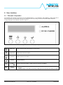
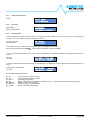
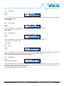
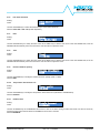
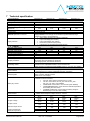
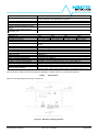
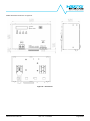
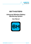
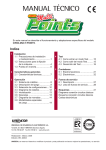
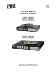
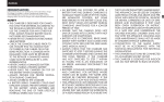
NPS2400 2400W High Efficiency Power Supply User’s Manual DISCLAIMER NEXTYS reserves the right to make changes without further notice to any products herein. NEXTYS makes no warranty, representation or guarantee regarding the suitability of its products for any particular purpose, nor does NEXTYS assume any liability arising out of the application or use of any product, and specifically disclaims any and all liability, including without limitation consequential or incidental damages. “Typical" parameters which may be provided in NEXTYS data sheets and/or specifications can and do vary in different applications and actual performance may vary overtime. All operating parameters, including “Typicals", must be validated for each customer application by customer's technical experts. NEXTYS does not convey any license under its patent rights nor the rights of others. NEXTYS products are not designed, intended, or authorized for use as components in systems intended for surgical implant into the body, or other applications intended to support or sustain life, or for any other application in which the failure of the NEXTYS product could create a situation where personal injury or death may occur. Should Buyer purchase or use NEXTYS products for any such unintended or unauthorized application, Buyer shall indemnity and hold NEXTYS and its officers, employees, subsidiaries, affiliates, and distributors harmless against all claims, costs, damages, and expenses, and reasonable attorney fees arising out of, directly or indirectly, any claim of personal injury or death associated with such unintended or unauthorized use, even if such claim alleges that NEXTYS was negligent regarding the design or manufacture of the part. The Customer should ensure that it has the most up to date version of the document by contacting its local NEXTYS office. This document supersedes any earlier documentation relating to the products referred to herein. The information contained in this document is current at the date of publication. It may subsequently be updated, revised or withdrawn. All Trade Marks recognized. Specifications and information herein are Subject to change without notice. NPS2400 User’s Manual Rev. 3.0 – 17.02.2015 Page 2/38 TABLE OF CONTENTS 1 2 3 4 Acronyms ................................................................................................................................................................................ 3 Introduction ............................................................................................................................................................................. 4 Functional description ............................................................................................................................................................. 6 Installing the NPS2400 ........................................................................................................................................................... 7 4.1 General considerations ..................................................................................................................................................... 7 4.2 Mounting and dismounting the device .............................................................................................................................. 8 4.3 Connecting the device ...................................................................................................................................................... 9 4.4 Maintenance ................................................................................................................................................................... 17 5 Operating modes .................................................................................................................................................................. 17 5.1 Overboost mode (default) ............................................................................................................................................... 17 5.2 Constant current limit mode ............................................................................................................................................ 18 5.3 Battery charger mode (available only on “-24” and “-48” models)................................................................................... 19 6 User interface ....................................................................................................................................................................... 21 6.1 Principles of operation .................................................................................................................................................... 21 6.2 Contrast adjustment ....................................................................................................................................................... 22 6.3 Initial and standard screens ............................................................................................................................................ 22 6.4 Set-up menu ................................................................................................................................................................... 24 6.5 Measurements ................................................................................................................................................................ 29 6.6 Event log ........................................................................................................................................................................ 30 6.7 Information ..................................................................................................................................................................... 35 7 Technical specification .......................................................................................................................................................... 36 7.1 Input ............................................................................................................................................................................... 36 7.2 Output............................................................................................................................................................................. 36 7.3 Interface ......................................................................................................................................................................... 36 1 Acronyms Acronym SMPS NPS2400_CB PFC PE SELV PELV FW NPS2400 User’s Manual Definition Switching Mode Power Supply. NPS2400 Communication board. Used to interface a PC to the SMPS. Power Factor Corrector Protective Earth Safety Extra Low Voltage Protective Extra Low Voltage Firmware Rev. 3.0 – 17.02.2015 Page 3/38 2 Introduction The NPS2400x series is a high power, high performance, CPU controlled 3-phase input SMPS family. These products present many advanced features such as: Very high efficiency (>92%) Compactness PFC input Operating also with DC input Wide range of output voltage Integrated active ORing circuit for all models Increased input protection against various mains abnormalities (overvoltage, surge, micro-interruptions, etc.) Remote shutdown Voltage sense function 4-20 mA and 0-10 V output current remote measurement User programmable auxiliary dry contact Load share (up to 4 units can be paralleled for redundancy or power increase) 3 operating modes: o Overboost which can deliver up to 150% of the rated current for a maximum of 5 seconds o Constant current o Lead-acid and NiCd/NiMH battery charger (only on “-24” and “-48” models) with temperature compensation Microcontroller based for: o Monitoring o Operating control and supervision User interface o Embedded user interface (4 user buttons, 2 LEDs and 1 LCD display): Displays real time status and alarms History of events, time stamped (a Real Time Clock is implemented) o PC application through USB interface (using an optional interface box NPS2400_CB): Remote configuration of the device Firmware upgrade Same functionalities of the embedded user interface with the ease of the PC benefits The NPS2400x family includes 4 models with 4 different output voltages and current ratings for a rated power of 2400 W (peak overload power of 3600 W). Model name NPS2400-24 NPS2400-48 NPS2400-72 NPS2400-170 Rated Vout [VDC] 24 48 72 170 NPS2400 User’s Manual Vout min [VDC] 11.5 23 50 85 Table 1 Vout max [VDC] Rated Iout /Ipeak[A] 29 100 / 150 56 50 / 75 87 33 / 50 175 14 / 21 Models ratings Rev. 3.0 – 17.02.2015 Rated /peak power [W] 2400 / 3600 2400 / 3600 2400 / 3600 2400 / 3600 Page 4/38 Figure 1 shows a front view of the SMPS with a short description of the main elements. Figure 1 NPS2400 front view Figure 2 shows the auxiliary connector I/Os. Figure 2 NPS2400 User’s Manual Auxiliary connector I/Os Rev. 3.0 – 17.02.2015 Page 5/38 3 Functional description A simplified block diagram of the NPS2400 is shown in Figure 3. Figure 3 NPS2400 simplified block diagram NPS2400 is a 3-phase input SMPS with 2 power stages, supervised by a microcontroller. The first stage is a power factor corrector (PFC) module that improves unit efficiency and reduces the harmonic current from the mains. The second stage is a resonant full bridge converter that provides primary to secondary insulation and high efficiency power conversion. The product offers additional features that improve the performances and the reliability: Integrated active ORing diode: allows connecting several devices in parallel for redundancy (see §4.3.4). When several units are paralleled for increase of the total output power (up to 8.7kW) this circuit increases the reliability of the system in case of 1 unit failure. Load share functionality: allows connecting up to 4 devices in parallel to increase the output power up to 8.7kW. A dedicated bus allows to equally share the total load current between the paralleled devices. Remote voltage sensing: allows regulating the output voltage directly at the load terminals compensating the cables and connectors voltage drop when long cables are used. Active surge protection: this circuit increases the reliability by protecting the device from high voltage transients occasionally present on the 3 phase mains. On top of that this circuit performs also the function of active inrush current limiter reducing the inrush current to very low values. Smart thermal management: the fans’ speed is controlled according to load and internal temperature conditions. This allows maintaining a safe temperature of the critical parts while maximizing the fans operating life and minimizing the fans noise. Remote output current measure: the user can measure remotely the output current delivered by the SMPS. The information is provided through an opto-isolated output with 2 industry standard ranges: 0…10V or 4…20mA for 0A to rated output current. Remote shutdown input: it allows to remotely switch the SMPS ON or OFF without cutting the 3 phase mains. An opto-isolated input can be configured as a remote shutdown/enable input Auxiliary 12V output: the units provide a regulated 12V/0.1A output completely insulated from the main output. It can be used to supply light 12V loads, independently on the SMPS output voltage/status. Battery charger mode (only on “-24” and “-48” models): this operating mode allows operating the device as a high performance battery charger for lead-acid and NiCd/NiMH batteries. 12V, 24V or 48V batteries can be charged up to a capacity of 1000Ah. NPS2400 User’s Manual Rev. 3.0 – 17.02.2015 Page 6/38 4 Installing the NPS2400 4.1 General considerations Warning: NPS2400 is a high voltage and high current SMPS. In order to avoid potentially hazardous situations including fire hazard, safety recommendations must be followed. Only authorized staff can install the unit. 4.1.1 Input voltage Vin= 3x400…500VAC (range=340…550VAC) or 520…750VDC. Use with only 2 phases connection is prohibited. Under emergency conditions only the units can operate with 2 phases input with reduced maximum power to ½ of the nominal. Connect the Earth (PE) wire before connecting L1/L2/L3 wires and keep it as short as possible. The wire gauge should be at least 1.5 mm2 (15 AWG). 4.1.2 Input protection devices NPS2400 is NOT equipped with an internal protection fuse. Use external breaking and protection devices as circuit breakers rated 10A and characteristic C, properly rated for the operating voltage and with a minimum breaking power of 1.5kA. OverCurrent protection must be provided on each phase. For USA and Canada use fuses class CC rated 10A. In some countries local regulation may apply. Special ratings and devices should be used for DC input applications. Call factory for information. Surge protection: it is strongly recommended to provide external surge arresters according to local regulations. 4.1.3 Input connector wiring The input mains terminal block accepts wires up to 4mm2 (11AWG). Strip the wire insulation for 8mm, screw tightening torque 0.5…0.6Nm, use only 60/75 Class 1 copper wires. Warning: before operating on the device disconnect the AC mains and wait at least 1 minute. 4.1.4 Output connector wiring The output terminal block accepts wires up to 35mm2 (2AWG). Strip the wire insulation for 15mm, screw tightening torque 2.5…4.5Nm, use only 60/75 Class 1 copper wires. Refer to Table 1 to define the minimum wire gauge for each model. Model name NPS2400C NPS2400D NPS2400G NPS2400R Rated Vout [VDC] 24 48 72 170 Table 2 Rated Iout [A] 100 50 33 14 Minimum wire gauge [mm2 /AWG] 25 / 3 10 / 7 6/9 2.5 / 13 Recommended output wire gauge 4.1.5 Auxiliary connector wiring The auxiliary terminal block accepts wires from 0.5mm 2 (20AWG) to 1.5mm2 (15AWG). Strip the wire insulation for 5mm, screw tightening 0.25Nm, use only 60/75 Class 1 copper wires. 4.1.6 Cooling Mount the device in vertical position, keep at least 80mm (3inch) free spacing on upper and lower side, 10mm (0.4inch) free spacing between adjacent devices. Check periodically that the air inlets in the enclosure are free from dust and other debris that can obstruct the air flow. Mount the device in the cooler zone of the cabinet. The thermal protection is activated if the surrounding air temperature is >50°C (122 °F) along with continuous full load operation. The device restarts automatically after cooling down. NPS2400 User’s Manual Rev. 3.0 – 17.02.2015 Page 7/38 4.2 4.2.1 Mounting and dismounting the device Mounting the device 2 1 Figure 4 Mounting the device on DIN rail Snap on the device on IEC60715/H35-7.5 rail; push the bottom side of the device towards the rail. The device will be automatically locked to the rail. 4.2.2 Dismounting the device 1 2 3 Figure 5 Mounting the device on DIN rail Pull down the slide using a screwdriver and then free the bottom part by rotating the device upwards. NPS2400 User’s Manual Rev. 3.0 – 17.02.2015 Page 8/38 4.3 4.3.1 Connecting the device Standard connection Figure 6 Standard device connection Figure 7 Standard device connection This is the basic configuration: connect the mains and the load using wires of appropriate gauge as stated in §4.1. Check the polarity of the output load before applying mains. NPS2400 User’s Manual Rev. 3.0 – 17.02.2015 Page 9/38 4.3.2 Connection with remote voltage sense Figure 8 Connection using remote voltage sense When the load is placed far away from the SMPS or when tight voltage accuracy is needed by the load, the NPS2400 provides a feature to compensate the output cables I*R voltage drop. It can tightly regulate the output voltage directly at the load terminals and not at the SMPS output terminal, within 10mV of precision. For applying this feature 2 additional cables (any flex wire from 0.5mm2 /20 AWG to 1.5mm2/15 AWG) are connected from the load terminals to the SMPS auxiliary connector SENSE+ and SENSE- terminals. It is strongly recommended to twist the 2 wires together in order to improve the noise and interference immunity. Please check and respect the polarity of the sense wires! If the polarity is reversed the SMPS output voltage of the SMPS will increase to its maximum. Although not harmful for the SMPS itself (an output overvoltage error will be triggered) this condition can damage the load. Note 1: The voltage displayed on the LCD screen is always the voltage at the SMPS output and not the voltage at the load terminals. Note 2: In case of very long output cables with consistent I*R cable drop the device could no more be able to deliver the rated output current. The rated output power is however maintained. Example: Vload=24V, cable drop=0.5 V (per cable), voltage at SMPS output=24V+2*0.5V=25V Maximum output current=2400W/25 V=96A (not 100A!). NPS2400 User’s Manual Rev. 3.0 – 17.02.2015 Page 10/38 4.3.3 Connection in series Figure 9 Connection of multiple units in series The series connection allows increasing the total output voltage. Connect the output terminals of each device in series checking the right polarity. Note 1: Before any power ON be sure to have connected the antiparallel diodes to all units. The voltage rating of EACH diode should cover the TOTAL voltage of the SERIES system. A diode as P600J is suitable for most applications. Note 2: Only SMPS of the same model (same rated output voltage) can be connected in series. Do not exceed > 4 units connected in series and > 200Vdc total voltage. For other situations contact the factory. Note 3: To achieve the best power sharing between the series connected devices it is recommended to regulate the output voltage of each device at the same value with a tolerance of maximum 0.1V. Note 4: When using several devices in series the operating mode must be set to OVERBOOST, using CONSTANT CURRENT mode can result in instabilities in case of load short circuit. The maximum current setpoint shall be the same on every connected device. : When the units are used in series do not connect anything to the auxiliary connector SENSE+/SENSE- and SHARE+/SHARE-. Any connection to these signals may damage the units and the connected load. NPS2400 User’s Manual Rev. 3.0 – 17.02.2015 Page 11/38 4.3.4 Connection in parallel (power and redundancy) Figure 10 Connection of multiple units in parallel The parallel connection may have one of the following purposes: 1) 2) Redundancy: several units (unlimited number in theory, 2...4 units in practice) can be used to increase the system reliability. If one SMPS fails the load will be still powered from another SMPS connected in parallel. The NPS2400 integrates an active ORing diode so that several units can be directly connected in parallel without the need for an external ORing module. In this configuration the maximum power sunk by the load must be < Pnom. The SHARE+/SHARE- signals should NOT be connected. Power increase: this configuration is used to increase the system power capacity by summing the output current of each individual SMPS connected in parallel to the load. To obtain the system’s best performance SHARE+/SHAREsignals must be daisy chain connected on all SMPS’. This allows equal current sharing between all the SMPS’. Note 1: When used in parallel for power increase the maximum number of SMPS is 4 units. Note 2: When used in parallel for power increase the maximum total output current will be 0.9*Iout*N, where N is the number of connected SMPS’. The maximum power is thus limited to 0.9*N*Pnom<8.7kW. Note 3: To achieve the best power sharing between the parallel connected devices the output voltage of each device must be adjusted at the same value with a tolerance of maximum 0.2V. The share bus will then slightly vary the output voltage of each SMPS to achieve the best possible power sharing. Do not connect anything to the auxiliary connector SENSE+/SENSE- when using the SHARE+/SHAREconnection! Wrong connection to these signals may damage the devices and the connected load. Respect the polarity of the SHARE+/SHARE- connections! NPS2400 User’s Manual Rev. 3.0 – 17.02.2015 Page 12/38 4.3.5 Battery charger connection (only on “-24” and “-48” models) Figure 11 Connection when used as battery charger The “-24” and “-48” models feature a function of battery charger, “-24” model can charge 12V and 24V batteries with capacity from 50Ah to 1000Ah while “-48” model can charge 48 V batteries only with capacity ranging from 25Ah to 500Ah. The device has an input for an optional 10k NTC (Murata NPSD0XH103FEB0 or equivalent) used to sense the battery ambient temperature. When using the temperature sensor the battery can be recharged in a more accurate way since the device regulates its charging voltage according to the battery ambient temperature. Respect the battery polarity! The device is NOT protected against battery polarity reversal. A connection with wrong battery polarity will damage the device and generate a fire hazard. NPS2400 User’s Manual Rev. 3.0 – 17.02.2015 Page 13/38 4.3.6 Output current remote measurement Figure 12 Figure 13 0…10V output for SMPS output current remote measure connection 4…20mA output for SMPS output current remote measure connection The NPS2400 provides 2 different outputs for the remote measurement of the current delivered by the device. The 2 outputs follow 2 major industry standards levels: 0…10V voltage output: 0V corresponds to 0A output, 10V corresponds to the rated output current of the SMPS 4…20mA current output: 4mA corresponds to 0A output, 20mA corresponds to the rated output current of the SMPS Note: The 2 outputs are floating with respect to the SMPS output (opto-isolated), but their ground is common to GND AUX. Take care of ground loops when using the remote current measurement in conjunction with the 12 V auxiliary output. Respect the connection polarity! NPS2400 User’s Manual Rev. 3.0 – 17.02.2015 Page 14/38 4.3.7 Remote shutdown input Figure 14 Figure 15 Remote shutdown input connection with external signal Remote shutdown input connection by using the AUX power supply The device includes an opto-isolated input used to remotely shutdown or enabling the device output without the need for disconnecting the mains input. This input can be used in 2 ways: a) b) External signal: when applying an external DC voltage as shown on Figure 14 from 5VDC to 24VDC to the SHUTDOWN inputs the NPS2400 output will be turned ON or OFF depending on the programmed shutdown polarity (see §6.4.9). External switch or relay contact: by connecting an external switch or relay contact as indicated in Figure 15 the NPS2400 output can be switched ON or OFF by only acting on the switch or relay contact. 4.3.8 Auxiliary 12V/100mA output The NPS2400 provides an auxiliary power supply rated 12V/100mA (max.). This supply is available on the +12V AUX/ GND AUX terminals of the auxiliary connector. The auxiliary supply is floating (isolated) with respect to the SMPS output. Take care when using the 12V auxiliary output in conjunction with remote output current measurement to avoid ground loops. The 12V auxiliary output is short circuit protected by an active circuit. 4.3.9 Auxiliary relay dry contacts NPS2400 provides an SPDT relay with normally open (NO) and normally closed (NC) dry contacts. They normally indicate that the output voltage is present and regulated (DCOK). Other functions are available for the relay, see chapter 6.4.18, 6.4.19, 6.4.20 and 6.4.21 for details. When the device is operating in battery charger mode (only on “-24” and “-48” models) the relay is excited when the battery charging process is terminated, overriding all the other functions. NPS2400 User’s Manual Rev. 3.0 – 17.02.2015 Page 15/38 4.3.10 Connection to a PC through the USB communication box NPS2400_CB Figure 16 Connection of the USB communication box (optional) The NPS2400 is provided with a connector called communication interface where the USB communication box NPS2400_CB (optional) must be connected. This allows interacting with the device using a PC provided with USB interface and a specific PC application (“POWER MASTER”) optionally provided. NPS2400 User’s Manual Rev. 3.0 – 17.02.2015 Page 16/38 4.4 Maintenance The FAN should be checked periodically (recommended: every 6 moths). Dirty fans can be cleaned using compressed air generated by a vacuum cleaner from outside of the unit. Do not use high pressure air flux, it can damage the unit. Optionally a maintenance reminder can be activated by factory (see §6.6.20). The remainder will be activated after a user definable hours of operation. To acknowledge the reminder the user must keep the button up and the button down pressed for more then 3 second. 5 Operating modes NPS2400 power supply has 3 different operating modes, user selectable (see §6.4.12). Overboost (OB) Constant current limit (CC) Battery charger (BC- available only on “-24” and “-48” models) 5.1 Overboost mode (default) Uout NPS2400 in Overboost mode can provide a temporary power boost up to 150% (3600W) of its rated power for a maximum of 5 seconds. This mode is suitable for powering loads with high inrush current such as motors or highly capacitive loads. It also helps in blowing fuses of failed loads and separate those from other active loads connected in parallel. The output U/I behaviour in OB mode is presented in Figure 17. Hiccup cycle after 5sec Unom 0.1*Unom Hiccup cycle Inom Figure 17 1.5*Inom Iout Output voltage vs. current characteristics in Overboost mode As soon as the output current becomes > Inom a timer is started; when the timer elapses (5 s) the output is shut OFF and kept OFF for 10 seconds (hiccup cycle – 5 s ON/10 s OFF). In case of a “dead short circuit” on the output (Uout<0.1*Unom) the maximum current is still limited at 1.5*Inom, but the output shuts off after about 100 ms entering a hiccup cycle. NPS2400 User’s Manual Rev. 3.0 – 17.02.2015 Page 17/38 5.2 Constant current limit mode Uout When operating in constant current limit mode NPS2400 behaves as a constant voltage source or constant current source depending on the load. CC mode is suitable for powering loads that do not need high peak currents. The output maximum current can be set between 0.1*Inom and Inom (see §6.4.5). It will never exceed the programmed value independently on the load behavior. In case of a “dead short circuit” on the output (Uout<0.1*Unom) Imax is still limited at Inom, but the output shuts OFF after about 100 ms, entering a hiccup cycle. This mode can be suitable also for powering systems that have a back-up battery in parallel to the load. The output U/I behavior in CC mode is presented in Figure 18. Unom 0.1*Unom Hiccup cycle Inom Figure 18 NPS2400 User’s Manual Iout Output voltage vs. current characteristics in constant current limit mode Rev. 3.0 – 17.02.2015 Page 18/38 5.3 5.3.1 Battery charger mode (available only on “-24” and “-48” models) Lead acid Stage 1 constant current charge Stage 2 Stage 3 constant voltage charge floating charge 0.20C 2.5 Current (A) 0.16C 2.0 0.12C 1.5 Charge current 0.08C 1.0 0.04C 0.5 3 6 9 Cell voltage (V) Cell voltage 12 Time (hrs) Figure 19 Lead acid battery charging profile This operating mode performs lead-acid battery charging. 12V, 24V or 48V batteries from 50Ah to 1000Ah can be charged. 2 charging modes are possible: normal charge and fast charge. In normal charge mode the charge current is limited to 0.1C (C = battery nominal capacity expressed in Ah) and the charging time takes approximately 12h. In fast charge mode the charge current is limited to 0.2C and the charging time is approximately 8h. The charging algorithm is shown in Figure 19, 3 stages are implemented: 1) Constant current charge: during this phase the SMPS operates as a constant current source limited at 0.1C or 0.2C. The battery voltage progressively increases until it reaches the constant voltage charge value. Stage 2 starts when this voltage is reached. 2) Constant voltage charge: during this phase the SMPS operates as a constant voltage source limited in current at 0.1C or 0.2C. The output voltage is kept constant at 14.4V for 12V batteries, 28.8V for 24V batteries or 57.6V for 48V batteries. If the external temperature sensor is used the constant voltage charge voltage is varied based on the battery ambient temperature (3 mV/°C). During this phase the current sunk by the battery starts to decrease. Stage 2 ends when the current sunk by the battery becomes lower than 0.03C or after 8 hrs of constant voltage charge. When Phase 2 is finished the DCOK LED is ON and the relay is excited, indicating that the charging process is completed. 3) Floating charge: during this phase the SMPS operates as a constant voltage source but the output voltage is decreased to 13.5V for 12V batteries, 27V for 24V batteries or 54V for 48V batteries. If the external temperature sensor is used the floating charge voltage is varied based on the battery temperature. This phase is used to compensate the battery selfdischarge current and to keep the battery at its maximum capacity. The charge ends after Phase 2, Phase 3 can be extended for an indefinite period of time, to keep the battery charged when not used. Battery voltage is checked before starting a charge cycle. For batteries that were deep discharged: if the battery voltage is < 8.4V for 12V batteries, < 16.8V for 24V batteries or < 33.6V for 48V batteries the charger tries to revive the battery. During revive the battery is charged with 0.04C. If after 10 hours the voltage on the battery still too low a battery error is triggered, otherwise a charging cycle is started (Stage 1). To exit the error state the user must acknowledge the error using the OK button. NPS2400 User’s Manual Rev. 3.0 – 17.02.2015 Page 19/38 5.3.2 Nickel (NiCd, NiMh) Stage 1 Stage 2 constant current charge trikle (float) charge battery voltage Battery charge voltage 0.1C Normal 0.2C Fast battery current 0.05C 16h Normal, 8h Fast Figure 20 Time Nickel battery charging profile This operating mode performs nickel battery charging, both NiCd and NiMh batteries can be charged. The charging algorithm is shown in Figure 20, 2 stages are implemented: 1) Constant current charge: during this phase the SMPS operates as a constant current source limited at 0.1C or 0.2C with the maximum voltage limited to the “Battery charge voltage” (§6.4.15) set. Stage 2 starts after 8h (fast charge) or 16h (normal charge). 2) Trickle (float) charge: the current is limited to 0.05C to avoid overcharge and compensate self-discharge of the battery. NPS2400 User’s Manual Rev. 3.0 – 17.02.2015 Page 20/38 6 User interface 6.1 Principles of operation An integrated user interface composed of an LCD (alphanumerical, 2 x 16 characters, with backlight), 2 status LEDs and 4 buttons is present on the NPS2400. Through this interface the user can modify, monitor and control the SMPS behaviour. The physical layout of the interface is shown in Figure 14. Figure 21 RED LED GREEN LED User interface physical layout MENU KEY Used to enter and exit various pages in the user menu. DOWN KEY Scrolls down menus and values. UP KEY Scrolls up menus and values. OK KEY Confirms selection ALARM Shows an abnormal condition (either external or internal to the SMPS) DC OK / CHARGE 1. in power supply modes: shows that the device is operating correctly and the output voltage is regulated 2. in battery charger mode: blinks (1Hz) during charging and turns ON when the battery is charged NPS2400 User’s Manual Rev. 3.0 – 17.02.2015 Page 21/38 6.2 Contrast adjustment While in DEFAULT SCREEN keep the OK KEY pressed for at least 3 seconds and then use the UP/DOWN KEYS to adjust the desired LCD contrast. 6.3 Initial and standard screens Initial and standard screens are shown in Figure 22: Down Key POWER-ON TEST SCREEN UP Key SETUP EDIT 1.5 seconds elapsed MEASUREMENT Menu Key ID SCREEN DEFAULT SCREEN 3 seconds elapsed EVENTS LOG UNIT INFO Figure 22 User interface layout When the SMPS is energized a POWER ON TEST is performed and a specific screen is displayed. This test checks the digital controller. Once the test is concluded an ID SCREEN is shown for 3 seconds. Consequently the DEFAULT SCREEN is shown. To activate the menu the user must press the MENU KEY, to exit the menu user can press on the MENU KEY again. Once the menu is enabled the user presses the UP/DOWN KEYS to scroll between submenus. The available menus are: 1) 2) 3) 4) SET-UP: MEASUREMENTS: EVENTS LOG: UNIT INFO: used to configure the SMPS by the user used to monitor SMPS voltages, currents and temperature accesses various logged events (alarms and errors). All are provided with a time stamp. displays specific information of the unit If there is no activity in a submenu for >1 min, the DEFAULT SCREEN is displayed. Detailed description of the submenus is given below. NPS2400 User’s Manual Rev. 3.0 – 17.02.2015 Page 22/38 6.3.1 Power ON test screen Self test in progress… Action: 6.3.2 ID screen Device Name: Device Serial Number: 6.3.3 NPS2400X xxxxxxxxxxxxxxxx Default screen This is the screen that appears any time if there is no activity on the other menus for >1 minute. It shows the on going alarms (if present) or the on-line values of the main parameters of the unit. Error or Alarm type: Offending value: OL Alarm Iout=103A Line 1 shows the error or alarm type, while line 2 shows the offending value causing it. When an alarm is present the ALARM LED is ON and the buzzer is active (if enabled). If no error or alarms are present and the mode is set to OVERBOOST or CURRENT-LIMIT the most significant measures are shown. Ui=xxxV Po=x.xkW Uo=xx.xV I=xxxA Uin, Pout: Uout, Iout: If no error or alarms are present and the mode is set to BATTERY-CHARGER the charger status and other useful measures are shown: Charger status, Temperature: Uout, Iout: BC_FLOAT xx.xC Uo=xx.xV I=xxxA The available charger statuses are: BC_CC BC_CV BC_FLOAT BC_OT BC_ERROR BC_REVIVE BC_CHECK : Constant Current charge in process : Constant Voltage charge in progress : Float Charge in progress : Battery environment over-temperature condition ( >50°C) – only if provided with optional Temp. sensor : Battery is faulty or not connected : Charger is trying to revive the battery : Battery is checked by the charger NPS2400 User’s Manual Rev. 3.0 – 17.02.2015 Page 23/38 6.4 Set-up menu From this submenu it is possible to configure the SMPS. The layout of the submenu is shown in Figure 23. Down Key SETUP EDIT Menu Key POWER LIMIT PRODUCT NAME UP Key Figure 23 VIN MIN ALARM RELAY ON AC OK VIN MAX ALARM RELAY ON TEMP OK VOUT RELAY ON IOUT OK IOUT MAX RELAY ON DC OK IOUT ALARM BATTERY CHARGE MODE DATE BATTERY CAPACITY TIME BATTERY CHARGING VOLTAGE SHUTDOWN POLARITY BATTERY NOMINAL VOLTAGE TEMPERATURE UNIT BATTERY TYPE BUZZER ENABLE OPERATIONAL MODE Edit settings layout By pressing the OK button user can start editing the selected parameter. Editing is done by scrolling the possible values with the UP/DOWN keys. If the KEYS are kept pressed they auto repeats at an accelerating frequency. To exit the edit mode press on the OK or MENU KEY. NPS2400 User’s Manual Rev. 3.0 – 17.02.2015 Page 24/38 6.4.1 Power Limit Setting: Value: Power limit: 2400W In case of operation in high temperature environment is possible to reduce the maximum power of the device. Possible choices are 1500W/2000W/2400W. Default: 2400W 6.4.2 Vin min alarm Setting: Value: Vin min alarm: 340V Use the UP/DOWN keys to select the minimum input voltage alarm threshold. Possible range is: 340 V < Vin min alarm < Vin max Alarm. Default: 340V 6.4.3 Vin max alarm Setting: Value: Vin min alarm: 520V Use the UP/DOWN keys to select the maximum input voltage alarm threshold. Possible range is: Vin min alarm < Vin max alarm < 520V Default: 520V 6.4.4 Vout Setting: Value: Vout: 24.00V [Io=0.0A] Use the UP/DOWN keys to set the desired output voltage within the possible values for each model. The range is model dependent and shown in Table 1.The actual output current is displayed in square brackets Default: 24.00V / 48.00V / 72.00V / 170.0V (model dependent) 6.4.5 Nominal Iout Setting: Value [actual output voltage]: Iout nom: 100A [Vo=24.00V] Use the UP/DOWN keys to set the desired nominal output current. In case of OVERBOOST mode 150% of this value is supplied for a maximum of 5 consecutive seconds. When the current exceeds this value an overload condition is triggered. The actual output voltage is displayed in square brackets. Default: 100A / 50A / 33A / 14A (model dependent) NPS2400 User’s Manual Rev. 3.0 – 17.02.2015 Page 25/38 6.4.6 Iout alarm threshold Setting: Value: Iout alarm: 100A Use the UP/DOWN keys to select the desired output current alarm threshold. Default: 100A / 50A / 33A / 14A (model dependent) 6.4.7 Date Date: Tue 04/01/2011 Setting: Value: Use the UP/DOWN keys to modify the date. Press OK or MENU key to advance the cursor to the next editable field, once the editable fields are finished press one more time to save and return to previous menu. 6.4.8 Time Setting: Value: Time: 11:19:38 Use the UP/DOWN keys to modify the time. Press OK or MENU key to advance the cursor to the next editable field, once the editable fields are finished press one more time to save and return to previous menu. 6.4.9 Remote shutdown polarity Setting: Value: Remote ShutDown: HIGH Use the UP/DOWN keys to modify the remote shut down polarity (LOW or HIGH). Default: HIGH 6.4.10 Temperature measurement unit Temp. unit: CELSIUS Setting: Value: Use the UP/DOWN keys to modify the temperature measurement unit (CELSIUS or FAHRENHEIT). Default: CELSIUS 6.4.11 Enable buzzer Setting: Value: Enable buzzer: DISABLED Use the UP/DOWN keys to enable/disable the buzzer in case of an alarm. During an alarm the buzzer can also be muted by pressing the OK button while in DEFAULT SCREEN for more than 3 seconds. Default: DISABLED NPS2400 User’s Manual Rev. 3.0 – 17.02.2015 Page 26/38 6.4.12 Operating mode Setting: Value: Operating mode: OVERBOOST Use the UP/DOWN key to select the desired operating mode between OVERBOOST / CURRENT LIMIT / BATTERY CHARGER (battery charger only available on the “-24” and “-48” models). Default: OVERBOOST 6.4.13 Battery type Setting: Value: Bat. type: Lead acid This submenu is present only if operating mode is set to BATTERY CHARGER. Use the UP/DOWN key to select the nominal battery type. Possible choices are “Lead acid” and “Nickel”. Default: Lead acid 6.4.14 Battery nominal voltage (only for lead acid on “-24” and “-48” models) Bat. nom. volt.: 12V Setting: Value: This submenu is present only if operating mode is set to BATTERY CHARGER. Use the UP/DOWN key to select the nominal battery voltage of lead acid batteries. Possible choices are 12V or 24V for “-24” model and 48V for “-48” model. Default: 12V / 48V (model dependent) 6.4.15 Battery charge voltage (only for nickel on “-24” and “-48” models) Bat. ch. volt.: 12.8V Setting: Value: This submenu is present only if operating mode is set to BATTERY CHARGER. Use the UP/DOWN key to select the battery charge voltage for NiCd/NiMH batteries. Range is 12.8V to 29V for “-24” model and 25.6V to 56V for “-48” model. Default: 12.8V / 25.6V (model dependent) 6.4.16 Battery capacity (only on “-24” and “-48” models) Setting: Value: Bat. capacity: 50Ah This submenu is present only if operating mode is set to BATTERY CHARGER. Use the UP/DOWN keys to select the nominal battery capacity. Range is 50Ah to 1000Ah for “-24” model and 25Ah to 500Ah for “-48” model. Default: 50Ah / 25Ah (model dependent) 6.4.17 Battery charge mode (only on “-24” and “-48” models) Setting: Value: Bat. ch. mode: NORMAL This submenu is present only if operating mode is set to BATTERY CHARGER. Use the UP/DOWN keys to select the desired battery charging mode between NORMAL (0.1C) or FAST (0.2C). Default: NORMAL NPS2400 User’s Manual Rev. 3.0 – 17.02.2015 Page 27/38 6.4.18 Relay active on “DC OK” Relay DC OK: ENABLED Setting: Value: Use the UP/DOWN key to enable/disable the relay on “DC OK”, the relay is excited when Vout>0.9*Vout_set. In BATTERYCHARGER mode this relay function is disabled. Default: ENABLED 6.4.19 Relay active on “Iout OK” Relay Iout OK: DISABLED Setting: Value: Use the UP/DOWN keys to enable/disable the relay on “Iout OK”, the relay is excited when Iout<Iout_alarm. In BATTERYCHARGER mode this relay function is disabled. Default: DISABLED 6.4.20 Relay active on “Temperature OK” Relay Temp OK: DISABLED Setting: Value: Use the UP/DOWN key to enable/disable the relay on “Temperature OK”, the relay is excited when the internal transformer temperature is < 110°C (230°F). In BATTERY-CHARGER mode this relay function is disabled. Default: DISABLED 6.4.21 Relay active on “AC OK” Relay AC OK: DISABLED Setting: Value: Use the UP/DOWN key to enable/disable the relay on “AC input OK” (means the AC voltage is within the user defined window), the relay is excited when the Vin_min_alarm<Vin<Vin_max_alarm. In BATTERY-CHARGER mode this relay function is disabled. Default: DISABLED 6.4.22 Product name Setting: Value: Product name: NPS2400 Use UP/DOWN key to change character and OK key to increment to the next string character. Default: NPS2400 NPS2400 User’s Manual Rev. 3.0 – 17.02.2015 Page 28/38 6.5 Measurements The UP/DOWN keys are used to scroll between pages. MENU key is used to return to the previous menu. The screen is refreshed every 500 ms. The average values are calculated from the beginning of the operation of the unit. 6.5.1 Page 1 Input voltage, output power: Output voltage, output current: 6.5.2 Page 2 Average output power: Average output current: 6.5.3 Pow.[av.]=xxxxW Iout[av.]=xxx.xA Page 3 Actual internal temperature: Average internal temperature: 6.5.4 Ui=xxxV Po=x.xkW Uo=xx.xV I=xxxA Temp[ac.]=xx.xC Temp[av.]=xx.xC Page 4 Charger status, Battery Ambient Temp.: Uout, Iout: BC_FLOAT xx.xC Uo=xx.xxV I=xxxA Output Measurements accuracy Input voltage Output voltage Output current Remote output current: Internal temperature External temperature NPS2400 User’s Manual 24V ±5% ±5VAC ±1% ±0.3V ±2% ±2A ±5% ±2A ± 4°C ± 4°C 48V ±5% ±5VAC ±1% ±0.6V ±3% ±2A ±5% ±2A ± 4°C ± 4°C Rev. 3.0 – 17.02.2015 72V ±5% ±5VAC ±1% ±0.9V ±3% ±2A ±5% ±2A ± 4°C ± 4°C 170V ±5% ±5VAC ±1% ±1.8V ±4% ±2A ±5% ±2A ± 4°C ± 4°C Page 29/38 6.6 Event log There are 3 categories of information saved by NPS2400 units (logged for further monitoring purposes) in a non-volatile memory. The maximum number of stored events is 408. When the storage capacity is reached the oldest event is overwritten. 1) ERRORS: these are critical events (either external or internal to SMPS) that impede the correct operation of the unit, leading to its shutdown. They are listed in Table 3. ID 0 1 2 3 4 5 6 7 8 Code OL OT OOV IUV IOV PUV POV PSF SC Name Over Load Over Temperature Output Over Voltage Input Under Voltage Input Over Voltage PFC Under Voltage PFC Over Voltage Phase Shift Failure Short Circuit Condition Iout > Inom for more then 5 seconds (hiccup) Transformer Temperature > 125°C (257°F) Vout > Max Vout Nominal Vin < 330V Vin > 530V Vpfc < 300V Vpfc > 450V While power converted is ON Vout = 0V & Iout = 0V While in Constant Current Mode Vout = 0V Table 3 Errors 2) ALARMS: these are events (either external or internal to SMPS) that are out of nominal values, but do not impede the operation of the unit. They are listed in Table 4. ID 20 21 22 23 24 25 26 27 28 29 Code OLS OLE OTS OTE IUVS IUVE IOVS IOVE Ph Loss St. Ph Loss End Name Over Load Start Over Load End Over Temperature Start Over Temperature End Input Under Voltage Start Input Under Voltage End Input Over Voltage Start Input Over Voltage End Phase Loss Start Phase Loss End Condition Iout > IoutAlarm (§6.4.6) Overload condition ends Transformer Temperature > 115°C (239°F) Over Temperature condition ends Vin < VinMinAlarm (§6.4.2) Input Under Voltage condition ends Vin > VinMaxAlarm (§6.4.3) Input Over Voltage condition ends SMSP working on two phases only Phase Loss condition ends Table 4 Alarms 3) EVENTS: These are standard operations (e.g. unit POWER ON or SHUT DOWN) which are logged just for reference of operating conditions. They are listed in 0. ID 40 41 50 Code Rem. ShDown Power ON BC CC 51 BC CV 52 53 54 BC Float BC Error BC OT 55 BC Revive Name Remote Shutdown Power ON Battery Charger Constant Current Battery Charger Constant Voltage Battery Charger Float Battery Charger Error Battery Charger Over Temperature Battery Charger Reviving Condition Remote Shutdown activated SMSP powered ON Battery starts Constant Current phase Battery start Constant Voltage phase Battery charged, float charge phase Battery Error, i.e. Vbat too low Battery ambient temperature < 50°C Battery charger is trying to revive the battery Table 5 Events The UP/DOWN keys are used to scroll between events. The log report is exportable to a PC see using interface box NPS2400_CB. NPS2400 User’s Manual Rev. 3.0 – 17.02.2015 Page 30/38 6.6.1 Over Load error Code, Type, Offending value: Time stamp: OL (ER) 142A ddmmyy hh:mm:ss Event: In OVERBOOST mode, Iout > Iout_nom for more then 5 seconds. The device enters a hiccup cycle. 6.6.2 Over Temperature error Code, Type, Offending value: Time stamp: OT (ER) 125C ddmmyy hh:mm:ss Event: transformer temperature > 125°C (257°F). The device trips to thermal shutdown. 6.6.3 Output Overvoltage error Code, Type, Offending value: Time stamp: OOV (ER) 32.0V ddmmyy hh:mm:ss Event: Unit internal error. The output voltage can be no more regulated and it trips to its maximum value. When such error occurs the device goes in a latched shutdown mode. A mains power cycle is needed to recover from such error. 6.6.4 Input Under Voltage error Code, Type, Offending value: Time stamp: IUV (ER) 325V ddmmyy hh:mm:ss Event: Vin < 330VAC. The SMPS remains switched off until Vin > 340VAC 6.6.5 Input Over Voltage error Code, Type, Offending value: Time stamp: IOV (ER) 545V ddmmyy hh:mm:ss Event: Vin > 530VAC. The SMPS remains switched off until Vin is decreased below 520VAC 6.6.6 PFC Under Voltage error Code, Type, Offending value: Time stamp: PUV (ER) 295V ddmmyy hh:mm:ss Event: VPFC < 300V. The internal PFC bus voltage can be no more regulated. When such error occurs the device goes in a latched shutdown mode. A mains power cycle is needed to attempt a recover from such error. Most of the cases this is an unrecoverable error and the device needs to be serviced. 6.6.7 PFC Over Voltage error Code, Type, Offending value: Time stamp: POV (ER) 455V ddmmyy hh:mm:ss Event: VPFC > 450V. The internal PFC bus voltage can be no more regulated. When such error occurs the device goes in a latched shutdown mode. A mains power cycle is needed to attempt a recover from such error. Most of the cases this is an unrecoverable error and the device needs to be serviced. NPS2400 User’s Manual Rev. 3.0 – 17.02.2015 Page 31/38 6.6.8 DC/DC ConverterFailure error Code, Type: Time stamp: PSF (ER) ddmmyy hh:mm:ss Event: Vout = 0V and Iout = 0A. The internal DC/DC converter is not working properly. When such error occurs the device goes in a latched shutdown mode. A mains power cycle is needed to recover from such error. Most of the cases this is an unrecoverable error and the device needs to be serviced. 6.6.9 Short Circuit error Code, Type: Time stamp: SC (ER) ddmmyy hh:mm:ss Event: While in CONSTANT CURRENT mode the voltage drops below 1V for more then 0.5 seconds. The device enters a hiccup cycle. 6.6.10 Over Load alarm start Code, Type, Offending value: Time stamp: OLS (AL) 100A ddmmyy hh:mm:ss Event: Iout > IoutAlarm (§6.4.6) 6.6.11 Over Load alarm end Code, Type, Maximum value: Time stamp: OLE (AL) 130A ddmmyy hh:mm:ss Event: Over Load condition alarm ends. Maximum value is the highest Iout measured during the alarm. 6.6.12 Over Temperature alarm start Code, Type, Offending value: Time stamp: OTS (AL) 115C ddmmyy hh:mm :ss Event: Transformer temperature > 115 °C (239 °F) 6.6.13 Over Temperature alarm end Code, Type, Maximum value: Time stamp: OTE (AL) 115C ddmmyy hh:mm :ss Event: Over Temperature alarm condition ends. Maximum value is the highest temperature measured during the alarm. 6.6.14 Vin Under Voltage alarm start Code, Type, Offending value: Time stamp: IUVS(AL) 330V ddmmyy hh:mm:ss Event: Vin < VinMinAlarm (§6.4.2). NPS2400 User’s Manual Rev. 3.0 – 17.02.2015 Page 32/38 6.6.15 Vin Under Voltage alarm end Code, Type, Minimum value: Time stamp: IUVE(AL) 310V ddmmyy hh:mm:ss Event: Vin Under Voltage alarm condition ends. Minimum value is the lowest Vin measured during the alarm 6.6.16 Vin Over Voltage alarm start Code, Type, Offending value: Time stamp: IOVS(AL) 545V ddmmyy hh:mm:ss Event: Vin > VinMaxAlarm 6.6.17 Vin Over Voltage alarm end Code, Type, Maximum value: Time stamp: IOVE(AL) 547V ddmmyy hh:mm:ss Event: Vin Over Voltage alarm condition ends. Maximum value is the highest Vin measured during the alarm 6.6.18 Phase Loss alarm start Code, Type: Time stamp: Ph Loss St. (AL) ddmmyy hh:mm:ss Event: A mains phase is missing for > 10s. In case of a phase loss alarm the maximum output power is reduced an half. 6.6.19 Phase Loss alarm end Code, Type: Time stamp: Ph Loss End (AL) ddmmyy hh:mm:ss Event: Phase Loss alarm condition ends. 6.6.20 Maintenance Due alarm start Code, Type: Time stamp: Maint. Due (AL) ddmmyy hh:mm:ss Event: Maintenance is due. 6.6.21 Maintenance Due alarm end Code, Type: Time stamp: Maint. OK (AL) ddmmyy hh:mm:ss Event: Maintenance done 6.6.22 Remote Shutdown event start Code, Type: Time stamp: Rem.Sh. St. (EV) ddmmyy hh:mm:ss Event: The device has been remotely shut down through the remote shutdown input. NPS2400 User’s Manual Rev. 3.0 – 17.02.2015 Page 33/38 6.6.23 Remote Shutdown event end Code, Type: Time stamp: Rem.Sh. End (EV) ddmmyy hh:mm:ss Event: The device exits remot shut down through the remote shutdown input. 6.6.24 Power On event Code, Type: Time stamp: Power ON (EV) ddmmyy hh:mm:ss Event: The unit has been energized. 6.6.25 Battery Charger Constant Current event. Code, Type: Time stamp: BC CC ddmmyy (EV) hh:mm:ss Event: In BC mode the unit started the constant current phase (see §5.3). 6.6.26 Battery Charger Constant Voltage event Code, Type: Time stamp: BC CV ddmmyy (EV) hh:mm:ss Event: In BC mode the unit started the constant voltage phase (see §5.3). 6.6.27 Battery Charger Float event Code, Type: Time stamp: BC Float (EV) ddmmyy hh:mm:ss Event: In BC mode the unit started the constant voltage phase (see §5.3). 6.6.28 Battery Charger Error event Code, Type: Time stamp: BC ERROR (EV) ddmmyy hh:mm:ss Event: In BC mode the unit started the constant voltage phase (see §5.3). 6.6.29 Battery Charger Over Temperature event Code, Type: Time stamp: BC OT ddmmyy (EV) hh:mm:ss Event: In BC mode the unit started the constant voltage phase (see §5.3). NPS2400 User’s Manual Rev. 3.0 – 17.02.2015 Page 34/38 6.7 Information Factory set generic information (ID, etc.) is available under this menu. The UP/DOWN keys are used to scroll between the pages. 6.7.1 Model Item: Model code: 6.7.2 Serial Number Item: Serial number: 6.7.3 Date[dd/mm/yy] TUE 04/01/2011 Time Time [hh:mm:ss]: 14:09:27 Item: Time: 6.7.6 Firmware: V00.00 Date Item: Date: 6.7.5 Serial Number: 1234567890 Firmware Item: Firmware version: 6.7.4 Model: NPS2400C Mains event counter Item: Total count: Mains events: xxxxx This counter is incremented every time a mains related event happens. Mains related events are: Input Under Voltage, Input Over Voltage and Phase Loss. 6.7.7 Load event counter Item: Total count: Load events: xxxxx This counter is incremented every time a load related event happens. Load related events are: Over Load and Short Circuit. 6.7.8 Environmental event counter Item: Total count: Env. events: xxxxx The counter is incremented every time an environment related event happens. Environmental events are: SMPS Over Temperature and Battery Ambient Over Temperature. NPS2400 User’s Manual Rev. 3.0 – 17.02.2015 Page 35/38 7 Technical specification Parameter/Model 7.1 Wiring Rated Input Voltage, frequency Input Voltage Range Input current @ full load: @400VAC @500VAC Inrush current Power factor External protection on AC line Input protection 7.2 NPS2400-48 NPS2400-72 NPS2400-170 3-phase, protective Earth 3x400…500 VAC , 47…63 Hz or DC 340…550 VAC / 520…750 VDC 4.5A 4.5A 4.5A 4.5A 3.5A 3.5A 3.5A 3.5A <10A, active inrush current limiter > 0.92 @ full load 3x10A curve C circuit breaker, for DC - ask factory Surge protection: it is strongly recommended to provide external surge arresters according to local regulations. Active surge protection according to VDE0160 Input overvoltage (auto restart) Input undervoltage (auto restart) Phase loss (reduced output power) Internal PFC circuit failure (latched shutdown) Output Nominal output voltage Output voltage adjust range Nominal output current Maximum output current Line and load regulation Output Ripple and noise Hold Up time Output protections Operating modes 7.3 NPS2400-24 Input 24V 48V 72V 170V 11.5V…29V 23V…56V 50 V…86V 85V…175V 100A 50A 33A 14A 150A / 5 sec 75A / 5 sec 50A / 5 sec 21A / 5 sec <1% < 200mVpp >10ms independent from line voltage Overload (OL) and short circuit (either constant current or hiccup mode at 150% load, with user settable OL threshold) Overvoltage (active, with latched shutdown) Overboost: allows 150% output power for max. 5sec, then off for max. 10sec Constant current: adjustable between 10% and 100% load Battery charger: for lead acid and NiCd/NiMH (only on “-24” and “-48” models) Interface User Interface Status Signals Relay dry contact Optoisolated output current remote measurement Measurements accuracy Input Voltage Output Voltage Output Current Remote output current Internal temperature External temperature NPS2400 User’s Manual LCD display 16 x 2 characters, multi language 4 pushbutton keys for various commands and menu navigation “DC OK” green LED “Alarm” red LED, indicating a fault Alphanumeric LCD display Contact rating: 24V/1A Activated for various functions: “DC OK”: active when 0.9*Uset<Uout<1.1*Uset “AC OK”: active when Uin>Uin_min and Uin<Uin_max (Uin_min, Uin_max= user settable) “OVERLOAD”: active when I out> Iout max (user settable) “OVERTEMPERATURE”: active when the internal temperature is exceeding the Tmax value. “CHARGE COMPLETE”: active when the battery charge is finished (only on 24V and 48V models) 0…10V voltage output for output current 0…100% In 4…20mA current output for output current 0…100% In ±5% ±5VAC ±1% ±0.3V ±2% ±2A ±5% ±2A ± 4°C ± 4°C ±5% ±5VAC ±1% ±0.6V ±3% ±2A ±5% ±2A ± 4°C ± 4°C Rev. 3.0 – 17.02.2015 ±5% ±5VAC ±1% ±0.9V ±3% ±2A ±5% ±2A ± 4°C ± 4°C ±5% ±5VAC ±1% ±1.8V ±4% ±2A ±5% ±2A ± 4°C ± 4°C Page 36/38 N+1 redundancy Parallel connection with current share Remote voltage sensing Remote shutdown input Auxiliary low power 12V output Optional: External temperature sensor (NTC) Optional: communication interface NPS2400_CB GENERAL Efficiency (%) Dissipated power Operating temperature Thermal protection Cooling method Input / output isolation Input / ground isolation Output / ground isolation Protection degree Safety standards / approvals EMC emissions EMC immunity Input connection terminal block Output connection terminal block Auxiliary connection terminal block Size (W x H x D) Weight Rail mounting information Up to 4 units in parallel with integrated active ORing circuit Up to 4 units (8.7kW total) using dedicated share bus connection Current sharing accuracy better than 5% @ 0.9*In Up to 1V output cables I*R drop compensation Optoisolated input for remote SMPS shutdown or SMPS enable Optoisolated 12V output, max 100mA load To be used when battery charging must be temperature compensated Includes USB port for remote monitoring and control of the unit >92% >92% >93% >92% <200W <200W <180W <200W -20° to +50°C (+60°C with derating) [-4°F to +122°F (+140°F with derating) YES, auto reset Forced air cooling with variable air flow; temperature and load controlled long life fans 2.85kVdc / 60s (type test) 2.25kVdc / 60s (type test) 0.75kVdc / 60s (type test) IP20 UL508 EN61000-6-4 EN61000-6-2, EN61000-4-5. surge immunity Level IV, VDE0160 Screw type 4mm2 [AWG 11] Screw type up to 35mm2 [AWG 2] Pluggable 1 x 16 pins, #3.81mm [0.15 in], max. 1.5mm 2 [AWG 15] 233 x 158 x102mm [9.17 x 6.22 x 4.00 in] 2.8kg [6.17 lbs] Vertical, allow 80mm [3.15in] spacing between TOP/BOTTOM adjacent items Horizontal, allow 10mm [0.40in] spacing between LEFT/RIGHT adjacent items Note: all values on Table 6 are TYPICAL measured values@ 3 x 400VAC and 25°C, if not otherwise specified. Table 6 Specifications Minimum mounting clearances are shown on Figure 24. Figure 24 NPS2400 User’s Manual Minimum mounting clearance Rev. 3.0 – 17.02.2015 Page 37/38 SMPS dimensions are shown on Figure 25. Figure 25 NPS2400 User’s Manual Dimensions Rev. 3.0 – 17.02.2015 Page 38/38