1
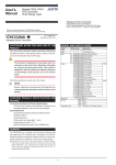
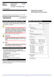
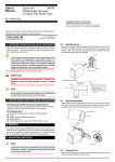
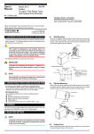
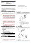
User's Manual Models WR5A, WR5V RTD Converter (Free Range Type) Network Solutions Business Division 2-9-32, Naka-cho Musashino-shi, Tokyo 180-8750 Japan Phone: +81-422-52-7179 Facsimile: +81-422-52-6619 Thank you for purchasing the JUXTA Signal Conditioner. Please read through this manual before use for correct handling. IM 77J09R05-01E 1st Edition Jan.2007 (YK) CAUTIONARY NOTES FOR SAFE USE OF THE PRODUCT MODEL AND SUFFIX CODES Model WR5A WR5V Input Suffix codes Description - - *C / RTD Converter (Free Range Type) -1 Pt100 (IPTS-68, JIS'89) -2 JPt100 (JIS'89) -3 Pt50 (JIS'81) -4 Pt100 (ITS-90) -0 Custom order WR5A Output A 4 to 20 mA DC B 2 to 10 mA DC C 1 to 5 mA DC 0 to 20 mA DC D E 0 to 16 mA DC F 0 to 10 mA DC G 0 to 1mA DC Z (Custom order) Direct current signals WR5V 1 0 to 10 mV DC 2 0 to 100 mV DC 3 0 to 1 V DC 4 0 to 10 V DC 5 0 to 5 V DC 6 1 to 5 V DC 7 -10 to 10 V DC 0 (Custom order) Direct voltage signals Power supply -1 24V DC ± 10% -2 100-240V AC (-15%, +10%) 50/60Hz Style code *C Style C Burnout /BU Up /BD Down /BN None Special option /D0 Dual outputs (1 to 5V DC) /DF Fahrenheit (°F) display function This User’s Manual should be carefully read before installing and operating the product. The following symbol is used on the product and in this manual to ensure safe usage. This symbol is displayed on the product when it is necessary to refer to the User's Manual for information on personal and instrument safety. This symbol is displayed in the User's Manual to indicate precautions to avoid danger to the operator, such as electric shock. The following symbols are used only in this manual. NOTE Draws attention to essential information for understanding the operations and/or functions of the product. CHECKING PRODUCT SPECIFICATIONS AND PACKAGE (1) Checking the Model and Product Specifications Check that the model and specifications indicated on the nameplate attached to the main unit are as ordered. (2) Packaged Items Check that the package contains the following items: WR5A or WR5V: 1 Mounting block: 2 Tag number and range label : 1 each Mounting screw (M4 x 0.7): 4 User’s Manual (this manual: IM 77J09R05-01E) GENERAL The WR5A/WR5V is a compact, front terminal connection and free range type RTD converter that is connected to an IEC/JISstandard resistance temperature detector (RTD) to convert temperature signals into isolated DC current or DC voltage signals. Selection of input type, I/O range setting, burnout setting, output adjustment, I/O monitoring, and loop back test can be made using the optional Parameter Setting Tool (VJ77) or Handy Terminal (JHT200). 1. MOUNTING METHOD 1.4 DIN Rail Mounting 1.1 Installing/Uninstalling the Mounting Block Locate the converter so that the DIN rail fits into the upper part of the DIN-rail groove at the rear of the socket, and fasten the socket using the slide lock located underneath the socket. To remove the converter, pull down the slide lock using a slotted screw-driver. The mounting block is necessary for rack mounting or wall mounting. Installing the mounting block Fit the mounting block into the grooves of the converter, and slide it in the direction of an arrow as shown belowleft. Uninstalling the mounting block Lift the stopper using a slotted screw-driver as shown below-right, and pull the mounting block to remove it. DIN rail DIN rail groove Mounting block Groove (Rack mounting) Groove (Wall mounting) Stopper Slide lock 1.5 Mounting Dimensions Unit: mm Angle Mounting Dimensions 24.5 24.5 24.5 24.5 24.5 1.2 Rack Mounting Take the FRK panel and install it on mounting angle as shown below. This method is suitable for high density mounting of the converters on a 19-inch rack panel. M4×0.7 Mounting screw Mounting angle Support FRK panel 73 90 nx49+2 Mounting angle Wall Mounting Dimensions 24.5 24.5 24.5 24.5 24.5 M4×0.7 Mounting screw M5 screw (4 places) Mounting screw (M4x0.7) (4 screws in the package) Mounting Dimensions 90 465±1 Unit: mm 450±1 2. INSTALLATION LOCATION 1.3 Wall Mounting Avoid the following environments for installation locations: Areas with vibration, corrosive gases, dust, water, oil, solvents, direct sunlight, radiation, a strong electric field, and/or a strong magnetic field, altitude of more than 2000m above sea level. If there is any risk of a surge being induced into the power line and/or signal lines due to lightning or other factors, a dedicated lightning arrester should be used as protection for both this converter and a field-installed device. Operating temperature/humidity range: 0 to 50C/5 to 90%RH (no condensation) Mount the converter onto the FRK panel as shown below or mount it directly on the wall. 3. EXTERNAL WIRING 50 25 Mounting angle 25 50 Supplied spacer(50) or Wiring space(30 to 60) WARNING FRK panel Be sure to turn OFF the power supply before wiring to avoid the risk of electric shock. Use a tester or similar device to ensure that no power is being supplied to a cable to be connected. M4 screw terminals are provided for the connection of external signals. Attach a crimp-on lug to each wire for connection to the terminals. Recommended cables: A nominal cross-sectional area of 0.5 mm2 or thicker for signal cables, and that of 1.25 mm2 or thicker for power cables. IM 77J09R05-01E 1st Edition 2007.01.15-00 4. SETTING PARAMETERS Wiring Diagram Input (RTD) A B B 8 4 7 7 4 8 Power supply L+ N− GND 14 15 The parameters are set as you specified in your order. Refer to the following to change the default settings. Set the parameters using a PC (VJ77 Parameter Setting Tool) or the Handy Terminal. Refer to "5. List of Parameters" in this manual and the User’s Manual for VJ77 PC-based Parameters Setting Tool (IM 77J01J77-01E) or the User’s Manual for JHT200 Handy Terminal (IM JF81-02E). Parameters are shown in brackets "[ ]". Output 2 (opt.) 9 + 10 − Output 1 9 10 11 12 14 15 16 11 + 12 − Connection of Setting Tools 16 JHT200 Handy Terminal JUXTA communication cable 3 pin connector (F9182ED) [Provided with VJ77 and JHT200] NOTE ●Do not connect anything to the terminals that are not used in the wiring diagram. Otherwise it may cause the malfunction or damage. ●The power line and input/output signal lines should be installed away from noise-generating sources. Otherwise accuracy cannot be guaranteed. ●The wiring resistance of input terminals and should be the same. ●The grounding resistance must be 100Ω (JIS Class D grounding). The length and thickness of the grounding cable should be as short and thick as possible. Directly connect the lead from the ground terminal of the product to the ground. Do not carry out daisy chained inter-ground terminal wiring. ●The ground terminal becomes effective for AC power only. ●Adhere strictly to the specifications to avoid overheating or damage. Before turning on the power, ensure the following: (a) Power supply voltage and input signal value applied to the product should meet the required specifications. (b) The external wiring to the terminals and wiring to ground are as specifications. ●Do not operate the product in the presence of flammable or explosive gases or vapors. ●The product is sensitive to static electricity; exercise care when in operation. Before you operate the product, touch a nearby metal part to discharge static electricity. VJ77 Dedicated adapter (E9789HA) [Provided with VJ77] Dedicated cable (E9786WK) [Provided with VJ77] PC with VJ77 installed *Be sure to use the VJ77 of version R1.05 or later. Setting RTD Type Set the RTD type to be connected to the input in [B05: TYPE]. Display Type of input PT Measuring range -200 to 660°C Pt100 (IPTS-68:JIS'89) JPT JPt100 (JIS'89) -200 to 10°C PT100-90 Pt100 (ITS-90:JIS'97) -200 to 850°C PT50 Pt50 (JIS'81) -200 to 649°C Measuring span 10°C or more JPt100 (JIS'89): R0=100Ω, R100/R0=1.3916 Pt100 (IPTS-68): R0=100Ω, R100/R0=1.3850 Pt100 (ITS-90): R0=100Ω, R100/R0=1.3851 Setting Temperature Unit Set the temperature unit of the input range in [B09: UNIT] NOTE Do not set the "-----" as the temperature unit, even if it is displayed during the setting. Otherwise it may cause the malfunction or damage. Power Supply and Isolation Power supply voltage: 100 to 240V AC (-15%, +10%) 50/60Hz 24V DC ±10% (ripple: less than 5% p-p) Current consumption DC: WR5A 65mA, WR5V 50mA Power consumption: 100V AC: WR5A 4VA, WR5V 3VA 200V AC: WR5A 5.5VA, WR5V 4.5VA Insulation resistance: 100 MΩ at 500 V DC between input, output, power supply, and grounding terminals mutually. Withstand voltage: DC: 1500V AC/minute between input-output, inputpower supply 500V AC/minute between output-power supply AC: 1500V AC/minute between input, output, power supply, and grounding terminals mutually. Setting Input Range Set the zero percent value of input range in [B10: ZERO], and the span of input range in [B11: SPAN]. Setting Burnout Action Set the burnout action in [B12: BURN OUT] Set "OFF", "UP", or "DOWN." NOTE Input adjustment should be applied when the setting of input range, burnout action direction or input wiring has been changed. IM 77J09R05-01E 1st Edition 2007.01.15-00 5. LIST OF PARAMETERS Parameter Display A DISPLAY A01 INPUT A02 OUTPUT A03 STATUS A04 REV NO B SET B01 TAG NO.1 B02 TAG NO.2 B03 COMMENT1 B04 COMMENT2 B05 TYPE B09 UNIT B10 ZERO B11 SPAN B12 BURN OUT C ADJUST C01 OUT 0% C02 OUT 100% C04 ZERO ADJ C05 SPAN ADJ Use the setting tool (VJ77 Parameter Setting Tool or JHT200 Handy Terminal) to adjust the input/output signals. Items Display Input value Output value Status (*1) Revision number. Setting Tag number 1 Tag number 2 Comment 1 Comment 2 Input type Unit Zero (0% of input range) Span (Input span) Burnout Adjustment Output 0% adjustment Output 100% adjustment Input zero adjustment Input span adjustment Input Adjustment Procedure (1) (2) (3) (4) (5) (6) Output Adjustment Procedure *1: This “STATUS” is for the customer’s engineer to check the history. When adjusting 0% value of output: (1) Set the adjustment value 0% in the parameter [C01: 6. MAINTENANCE OUT 0%]. •The value equivalent to 0% of the output range will be output, irrespective of the input. (2) Check the output value via digital multimeter, and adjust it in the parameter [C01: OUT 0%]. •If it slips out to the (+) side, set (−) value equivalent to slipout; if it slips out to the (−) side, set (+) value equivalent to slipout for adjusting the output value to 0%. *: The 100% value of output can be adjusted by the same operation as the above in [C02: OUT 100%]. The product starts running immediately when the power is turned on; however, it needs 10 to 15 minutes of warm-up before it meets the specified performance. 6.1 Calibration Apparatus A 6-dial variable resistor (Yokogawa Meters & Instruments Corporation 279301 or equivalent) A digital mutimeter (Yokogawa 7561 or equivalent) A precision resistor of 250 Ω ±0.01%, 1W A setting tool for adjustment (Refer to "4. Setting Parameters" in this manual. 6.2 Calibration Procedure For adjustment using a setting tool, refer to the User’s Manual for each setting tool and “5. List of Parameters” in this manual. User’s Manual for VJ77 [Document No.: IM 77J01J77-01E]; however, use the VJ77 of version R1.05 or later. User’s Manual for JHT200 [Document No.: IM JF81-02E] 1.Connect the instruments as shown below. Input 8 7 4 7 4 A B Input the value equivalent to 0% value of the input range to the converter. Read the parameter [C04: ZERO ADJ] and check the input value. Select “INC” or “DEC” in the parameter [C04: ZERO ADJ] to adjust. INC: Increase (Adjusts the increased value of the input [resistance] value) DEC: Decrease (Adjusts the decreased value of the input [resistance] value) RST: Reset of the adjustment value Input the value equivalent to 100% value of the input range to the converter. Read the parameter [C05: SPAN ADJ] and check the input value. Adjust the span in the same way as (3). 6-dial variable resistor B 8 Setting tool Output-1 9 10 11 12 11 12 14 15 16 L+ N− GND DMM Ro: 250Ω precision registor for current output Power supply 24V DC or 85 to 264V AC + Ro − 14 15 16 The ground terminal is used for AC power only. 2 Use the 6-dial variable resistor and apply the resistance equivalent to 0, 25, 50, 75, and 100% of the measuring range to the converter. 3.Verify that the corresponding output-1 voltage are 0, 25, 50, 75, and 100% respectively and within the specified accuracy rating. (Ro is used for current output.) For checking the output-2, connect the DMM to the output-2 terminals: + and -. The relative error with the output-1 should be within ±0.2%. IM 77J09R05-01E 1st Edition 2007.01.15-00