1
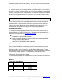
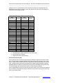
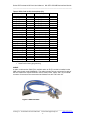
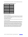
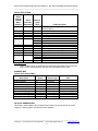
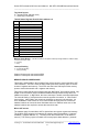
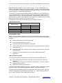
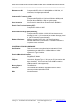
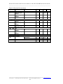
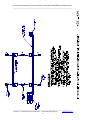
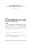
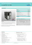
Series IP57x Industrial I/O Pack
MIL-STD-1553A/B Bus Interface Module
USER’S MANUAL
ACROMAG INCORPORATED
30765 South Wixom Road
P.O. BOX 437
Wixom, MI 48393-7037 U.S.A.
Tel: (248) 624-1541
Fax: (248) 624-9234
Copyright 2010, Acromag, Inc., Printed in the USA.
Data and specifications are subject to change without notice.
8500-892-A10J000
Series IP57x Industrial I/O Pack User’s Manual MIL-STD-1553A/B Bus Interface Module
________________________________________________________________________
Table of Contents
RELATED PUBLICATIONS ....................................................................................................3
GENERAL INFORMATION ....................................................................................................3
MODELS .................................................................................................................................3
KEY FEATURES .................................................................................................................4
INDUSTRIAL I/O PACK INTERFACE FEATURES ............................................................4
IP MODULE WINDOWS SOFTWARE ...............................................................................5
IP MODULE VxWORKS SOFTWARE ................................................................................5
IP MODULE LINUX SOFTWARE .......................................................................................6
PREPARATION FOR USE .....................................................................................................6
UNPACKING AND INSPECTION .......................................................................................6
CARD CAGE CONSIDERATIONS .....................................................................................6
INSTALLATION...................................................................................................................6
CONNECTORS...................................................................................................................6
IP Logic Interface Connector (P1) ...................................................................................6
IP Field I/O Connector (P2) .............................................................................................7
CABLE ................................................................................................................................8
Non-Isolation Considerations ..............................................................................................9
PROGRAMMING INFORMATION .........................................................................................9
IP IDENTIFICATION PROM ...............................................................................................9
ADDRESS MAP ................................................................................................................10
I/O SPACE ADDRESS MAP .............................................................................................10
MEMORY SPACE ADDRESS MAP .................................................................................12
Micro ACE access .............................................................................................................12
PROGRAMMING INTERRUPTS ......................................................................................14
THEORY OF OPERATION ..................................................................................................14
LOGIC/POWER INTERFACE ...........................................................................................14
IP INTERFACE LOGIC .....................................................................................................14
IP57xCONTROL LOGIC ...................................................................................................15
TAG CLOCK Input / Output ..............................................................................................15
STATIC MICRO ACE INPUTS..........................................................................................16
REMOTE TERMINAL ADDRESS .....................................................................................16
BUS CONNECTION .........................................................................................................16
DIRECT COUPLING METHOD.....................................................................................16
TRANSFORMER COUPLING METHOD ......................................................................16
SERVICE AND REPAIR .......................................................................................................16
PRELIMINARY SERVICE PROCEDURE .........................................................................17
WHERE TO GET HELP ....................................................................................................17
SPECIFICATIONS ................................................................................................................17
PHYSICAL ........................................................................................................................17
Connectors ........................................................................................................................17
INDUSTRIAL I/O PACK COMPLIANCE ...........................................................................18
________________________________________________________________________
Acromag, Inc. Tel:248-295-0310 Fax:248-624-9234
Email:[email protected]
2
www.acromag.com
Series IP57x Industrial I/O Pack User’s Manual MIL-STD-1553A/B Bus Interface Module
________________________________________________________________________
The information contained in this manual is subject to change without notice. Acromag,
Inc. makes no warranty of any kind with regard to this material, including, but not limited to,
the implied warranties of merchantability and fitness for a particular purpose. Further,
Acromag, Inc. assumes no responsibility for any errors that may appear in this manual and
makes no commitment to update, or keep current, the information contained in this manual.
No part of this manual may be copied or reproduced in any form, without the prior written
consent of Acromag, Inc.
IMPORTANT SAFETY CONSIDERATIONS
It is very important for the user to consider the possible adverse effects of power, wiring,
component, sensor, or software failures in designing any type of control or monitoring
system. This is especially important where economic property loss or human life is
involved. It is important that the user employ satisfactory overall system design. It is
agreed between the Buyer and Acromag, that this is the Buyer's responsibility.
RELATED PUBLICATIONS
The following manuals and part specifications provide the necessary information for in
depth understanding of the IP57x Series boards. These documents are available on the
Data Device Corporation web site http://www.ddc-web.com/.
BU-6174X/6184X/6186X ENHANCED MINIATURE ADVANCED
COMMUNICATIONS ENGINE data sheet
Enhanced Miniature Advanced Communications Engine (Enhanced Mini-ACE®
Series) Users Guide MN-6186X-001
MIL-STD-1553 DESIGNER’S GUIDE Sixth Edition
GENERAL INFORMATION
The Industrial I/O Pack 57x series modules provide the interface between the Industrial I/O
Pack (IP) bus and the MIL-STD-1553A/B bus. The IP57x series modules are built upon
Data Device Corporation’s Micro ACE MIL-STD-1553 terminal. The Micro ACE provides
Bus Controller (BC), Remote Terminal (RT), and Bus Monitor (BM) functions. The Micro
ACE includes 64K words of RAM for message queues. IP57x modules support both direct
and transformer coupled applications. A synchronization clock input and output is
provided. The RT address lines for each channel are available at the connector to allow
setting the RT address with the wire harness.
The IP-57x Series consists of four models with one or two dual redundant 1553 channels in
either the commercial or the industrial temperature range.
MODELS
Table 1 IP57x Series Models
Model
Number of
Channels
Operating Temperature
Range
IP571
IP572
IP571E
IP572E
1
2
1
2
0 to 70 C
0 to 70 C
-40 to 85 C
-40 to 85 C
________________________________________________________________________
Acromag, Inc. Tel:248-295-0310 Fax:248-624-9234
Email:[email protected]
3
www.acromag.com
Series IP57x Industrial I/O Pack User’s Manual MIL-STD-1553A/B Bus Interface Module
________________________________________________________________________
KEY FEATURES
One or two dual redundant MIL-STD-1553A/B channels
Each channel can be independently programmed for Bus Controller, Remote
Terminal, or Bus Monitor operation
Transformer (long stub) or Direct coupled (short stub) bus connection
64K words RAM per channel
External Time-Tag clock input and output
Software initiated RAM built in self test
RT address input for each channel
VITA 4 compliant
INDUSTRIAL I/O PACK INTERFACE FEATURES
Clock Speed – Supports an 8 or 32 MHz IP bus clock speed.
High density - Single-size, industry-standard, IP module footprint. Up to four units may be
mounted on a 6U VMEbus carrier board or five units may be mounted on a PCI carrier
board.
Local ID - Each IP module has its own 8-bit ID information which is accessed via data
transfers in the "ID" space.
16-bit & 8-bit I/O – Control and status register Read/Write is performed through 16 bit or 8
bit data transfer cycles in the IP module I/O space. The u-ACE controllers are located in
memory space and are accessed with 16-bit data transfer cycles.
High Speed - Access times for all data transfer cycles are described in terms of "wait"
states. For the supplied IP module example, wait states are minimized for all read and
write operations (see specifications for detailed information).
________________________________________________________________________
Acromag, Inc. Tel:248-295-0310 Fax:248-624-9234
Email:[email protected]
4
www.acromag.com
Series IP57x Industrial I/O Pack User’s Manual MIL-STD-1553A/B Bus Interface Module
________________________________________________________________________
CHANNEL 0
A
ID ROM
CONTROL
STATUS
CONTROL
ADDRESS
& DATA
DDC
µACE
1553
BC/RT/MT
B
RT ADDRESS
P1
P2
IP
BUS
TAG CLOCK IN
TAG CLOCK OUT
ADDRESS
CHANNEL 1
DATA
A
INTERRUPT
VECTORS
CONTROL
LOGIC
ADDRESS
& DATA
DDC
µACE
1553
BC/RT/MT
B
FPGA
RT ADDRESS
Figure 1 IP572 Block Diagram
IP MODULE WINDOWS SOFTWARE
Acromag provides a software product (sold separately) to facilitate the development of
Windows (2000/XP/Vista/7 ) applications accessing Acromag Industry Pack models
installed on Acromag PCI Carrier Cards and CompactPCI Carrier Cards. This software
(Model IPSW-API-WIN) consists of low-level drivers and Windows 32 Dynamic Link
Libraries (DLLs) that are compatible with a number of programming environments including
Visual C++™, Visual Basic .NET® and others. The DLL functions provide a high-level
interface to boards eliminating the need to perform low-level reads/writes of registers, and
the writing of interrupt handlers.
IP MODULE VxWORKS SOFTWARE
Acromag provides a software product (sold separately) consisting of board VxWorks
software. This software (Model IPSW-API-VXW) is composed of VxWorks (real time
operating system) libraries for all Acromag IP modules and Carriers, PCI I/O Cards, and
________________________________________________________________________
Acromag, Inc. Tel:248-295-0310 Fax:248-624-9234
Email:[email protected]
5
www.acromag.com
Series IP57x Industrial I/O Pack User’s Manual MIL-STD-1553A/B Bus Interface Module
________________________________________________________________________
CompactPCI I/O Cards. The software is implemented as a library of “C” functions which
link with existing user code to make possible simple control of all Acromag PCI boards.
IP MODULE LINUX SOFTWARE
Acromag provides a software product (available on website) consisting of board Linux®
software. This software (Model IPSW-API-LINUX) is composed of Linux® libraries for all
Acromag IP modules and carriers including the AVME9670 and AVME9660/9630. The
software supports X86 PCI bus only and is implemented as library of “C” functions. These
functions link with existing user code to make possible simple control of all Acromag IP
modules and carriers.
PREPARATION FOR USE
UNPACKING AND INSPECTION
Upon receipt of this product, inspect the shipping carton for evidence of mishandling
during transit. If the shipping carton is badly damaged or water stained, request that the
carrier's agent be present when the carton is opened. If the carrier's agent is absent
when the carton is opened and the contents of the carton are damaged, keep the carton
and packing material for the agent's inspection.
For repairs to a product damaged in shipment, refer to the Acromag Service Policy to
obtain return instructions. It is suggested that salvageable shipping cartons and packing
material be saved for future use in the event the product must be shipped.
This board is physically protected with packing material and electrically protected with an
anti-static bag during shipment. However, it is recommended that the board be visually
inspected for evidence of mishandling prior to applying power.
CARD CAGE CONSIDERATIONS
Refer to the specifications for loading and power requirements. Be sure that the system
power supplies are able to accommodate the power requirements of the carrier board, plus
the installed IP modules, within the voltage tolerances specified.
IMPORTANT: Adequate air circulation must be provided to prevent a temperature rise
above the maximum operating temperature.
The dense packing of the IP modules to the carrier board restricts air flow within the card
cage and is cause for concern. If the installation is in an industrial environment and the
board is exposed to environmental air, careful consideration should be given to air-filtering.
INSTALLATION
Power should be removed from the board when installing IP modules, cables, termination
panels, and field wiring. Refer to the IP Mechanical Assembly Drawing located in the
Drawings Section of this manual and assembly instructions.
CONNECTORS
IP Logic Interface Connector (P1)
P1 of the IP module provides the logic interface to the mating connector on the carrier
board. This connector is a 50-pin female receptacle header (AMP 173279-3 or equivalent)
which mates to the male connector of the carrier board (AMP 173280-3 or equivalent).
This provides excellent connection integrity and utilizes gold-plating in the mating area.
Threaded metric M2 screws and spacers are supplied with the IP module to provide
additional stability for harsh environments (see Drawing 4501-434 for assembly details).
Field and logic side connectors are keyed to avoid incorrect assembly. The pin
________________________________________________________________________
Acromag, Inc. Tel:248-295-0310 Fax:248-624-9234
Email:[email protected]
6
www.acromag.com
Series IP57x Industrial I/O Pack User’s Manual MIL-STD-1553A/B Bus Interface Module
________________________________________________________________________
assignments of P1 are standard for all IP modules according to the Industrial I/O Pack
Specification (see Table 2). However some logic signals not used for the IP interface are
reserved for factory programming.
Table 2 Standard Logic Interface Connections (P1)
Pin
Description
Number
Pin
Description
Number
GND
1
GND
26
CLK
2
+5V
27
1
Reset#
3
R/W#
28
D00
4
IDSEL#
29
D01
5
DMAReq0#
30
D02
6
MEMSEL#
31
D03
7
DMAReq1#
32
D04
8
IntSel#
33
D05
9
DMAck0#
34
D06
10
IOSEL#
35
3
D07
11
Reserved
36
D08
12
A1
37
D09
13
DMAEnd*
38
D10
14
A2
39
3
D11
15
Reserved
40
D12
16
A3
41
D13
17
INTReq0#
42
D14
18
A4
43
D15
19
INTReq1#
44
BS0#
20
A5
45
BS1#
21
STROBE#
46
2
-12V
22
A6
47
2
+12V
23
ACK#
48
3
+5V
24
Reserved
49
GND
25
GND
50
Notes :(Table 2)
1. An Asterisk (#) is used to indicate an active-low signal
2. Not Used by this IP Module
3. Reserved for factory programming
IP Field I/O Connector (P2)
P2 provides the field I/O interface connections for mating IP modules to the carrier board.
P2 is a 50-pin female receptacle header which mates to the male connector of the carrier
board. This provides excellent connection integrity and utilizes gold-plating in the mating
area. Threaded metric M2 screws and spacers are supplied with the module to provide
additional stability for harsh environments (see Mechanical Assembly Drawing 4501-434).
The field and logic side connectors are keyed to avoid incorrect assembly.
P2 pin assignments are unique to each IP model (see Table 3) and normally correspond to
the pin numbers of the field I/O interface connector on the carrier board (you should verify
this for your carrier board).
________________________________________________________________________
Acromag, Inc. Tel:248-295-0310 Fax:248-624-9234
Email:[email protected]
7
www.acromag.com
Series IP57x Industrial I/O Pack User’s Manual MIL-STD-1553A/B Bus Interface Module
________________________________________________________________________
Table 3 IP57x Field I/O Pin Connections (P2)
Pin Description
Number
Pin Description
CH0_RT_ADDR0
1
CH1_RT_ADDR0
CH0_RT_ADDR1
2
CH1_RT_ADDR1
CH0_RT_ADDR2
3
CH1_RT_ADDR2
CH0_RT_ADDR3
4
CH1_RT_ADDR3
CH0_RT_ADDR4
5
CH1_RT_ADDR4
CH0_RT_PARITY
6
CH1_RT_PARITY
GND
7
TAG_CLOCK_OUT
TAG_CLOCK_IN
8
GND
GND
9
GND
GND
10
CH1B_DIRECT_N
CH1B_XFMR_N
11
CH1B_DIRECT_P
CH1B_XFMR_P
12
GND
GND
13
GND
GND
14
CH1A_DIRECT_N
CH1A_XFMR_N
15
CH1A_DIRECT_P
CH1A_XFMR_P
16
GND
GND
17
GND
GND
18
CH0B_DIRECT_N
CH0B_XFMR_N
19
CH0B_DIRECT_P
CH0B_XFMR_P
20
GND
GND
21
GND
GND
22
CH0A_DIRECT_N
CH0A_XFMR_N
23
CH0A_DIRECT_P
1
CH0A_XFMR_P
24
Reserved
GND
25
Not connected
Note: (Table 3)
1. Reserved for factory programming
Number
26
27
28
29
30
31
32
33
34
35
36
37
38
39
40
41
42
43
44
45
46
47
48
49
50
CABLE
A cable, model number 5028-570 is available when an IP-57x module is installed on the
VME carrier board model AVME9668. The cable includes Twin-ax connectors for each of
the four transformer coupled channels: CH0A, CH0B, CH1A, CH1B, and a 15 pin DSUB
connector for access to the remote terminal address lines and TAG clock I/O.
Figure 2 5028-570 Cable
________________________________________________________________________
Acromag, Inc. Tel:248-295-0310 Fax:248-624-9234
Email:[email protected]
8
www.acromag.com
Series IP57x Industrial I/O Pack User’s Manual MIL-STD-1553A/B Bus Interface Module
________________________________________________________________________
Table 4 5028-570 Cable 15 Pin DSUB pin assignments
Pin Description
Number
CH0_RT_ADDR0
CH0_RT_ADDR1
CH0_RT_ADDR2
CH0_RT_ADDR3
CH0_RT_ADDR4
CH0_RT_PARITY
GND
TAG_CLOCK_IN
CH1_RT_ADDR0
CH1_RT_ADDR1
CH1_RT_ADDR2
CH1_RT_ADDR3
CH1_RT_ADDR4
CH1_RT_PARITY
TAG_CLOCK_OUT
1
2
3
4
5
6
7
8
9
10
11
12
13
14
15
Non-Isolation Considerations
The board is non-isolated, since there is electrical continuity between the logic and field I/O
grounds. As such, the field I/O connections are not isolated from the system. Care should
be taken in designing installations without isolation to avoid noise pickup and ground loops
caused by multiple ground connections.
PROGRAMMING INFORMATION
This Section provides the specific information necessary to program and operate the board.
IP IDENTIFICATION PROM
Each IP module contains identification (ID) information that resides in the ID space per the
IP module specification. This area of memory contains 32 bytes of information at most.
Both fixed and variable information may be present within the ID space. Fixed information
includes the "IPAH" identifier, model number, and manufacturer's identification codes.
Variable information includes unique information required for the module. The IP57x ID
information does not contain any variable (e.g. unique calibration) information. ID space
bytes are addressed using only the odd addresses in a 64 byte block (on the “Big Endian”
VMEbus). Even addresses are used on the “Little Endian” PC PCI bus. The IP57x ID
space contents are shown in Table 5. Note that the base-address for the IP module ID
space (see your carrier board instructions) must be added to the addresses shown to
properly access the ID space. Execution of an ID space read requires 1 wait state.
________________________________________________________________________
Acromag, Inc. Tel:248-295-0310 Fax:248-624-9234
Email:[email protected]
9
www.acromag.com
Series IP57x Industrial I/O Pack User’s Manual MIL-STD-1553A/B Bus Interface Module
________________________________________________________________________
Table 5 IP57x ID ROM
Hex
Offset
From ID
PROM
Base
Address
ASCII
Character
Equivalent
Numeric
Value
(Hex)
01
I
49
03
05
07
09
0B
P
A
H
50
41
48
A3
52
53
00
00
00
00
0C
0D
0F
11
13
15
17
19 to 3F
8F
EE
yy
Field Description
Format I ID ROM supports 8 or 32 MHz IP bus
clock frequency
Acromag ID Code
1
IP Model Code
IP571
IP572
Not Used (Revision)
Reserved
Not Used (Driver ID Low Byte)
Not Used (Driver ID High Byte)
Total Number of ID PROM Bytes
CRC
IP571
IP572
Not Used
Notes (Table 5):
1. The IP model number is represented by a two-digit code within the ID space (the
IP571 model is represented by 52H, the IP572 is represented by 53H).
ADDRESS MAP
Table 6 IP57x Address Map
Description
Control Register
Status Register
Channel 0 Interrupt Vector
Channel 1 Interrupt Vector
ID ROM
Channel 0 uACE registers
Channel 0 uACE RAM
Channel 1 uACE registers
Channel 1 uACE RAM
IP Address
Space
I/O
I/O
I/O
I/O
ID
Memory
Memory
Memory
Memory
Access Type
16 bit only
16 bit only
8 bit
8 bit
8 bit
16 bit only
16 bit only
16 bit only
16 bit only
Address Offset from
base
0
2
5
7
0x01 – 0x17
0x00000 – 0x0003E
0x20000 – 0x3FFFE
0x40000 – 0x4003E
0x60000 – 0x7FFFE
I/O SPACE ADDRESS MAP
This board is addressable in the Industrial Pack I/O space to provide access to control
registers, a status register, and interrupt vector registers.
________________________________________________________________________
Acromag, Inc. Tel:248-295-0310 Fax:248-624-9234
Email:[email protected]
10
www.acromag.com
Series IP57x Industrial I/O Pack User’s Manual MIL-STD-1553A/B Bus Interface Module
________________________________________________________________________
The I/O space may be as large as 64, 16-bit words (128 bytes) using address lines A1 to
A6, but the IP57x uses only a portion of this space. The I/O space address map for the
IP7x is shown in Table 6. Note that the base address for the IP module I/O space (see
your carrier board instructions) must be added to the addresses shown to properly access
the I/O space.
Table 7 Control Register Read / Write I/O base address + 0
Bit
Description
Reset State
15 - 14
13
12
11
10
9
8
7
6
5
4
3
2
1
0
IP bus clock
Channel 1 Transceiver Inhibit A
Channel 1 Transceiver Inhibit B
Channel 1 Master Clear
Channel 1 Built In Self Test Enable
Channel 1 Remote Terminal Address Latch
Channel 1 Interrupt Enable
Tag Clock Source
Not used
Channel 0 Transceiver Inhibit A
Channel 0 Transceiver Inhibit B
Channel 0 Master Clear
Channel 0 Built In Self Test Enable
Channel 0 Remote Terminal Address Latch
Channel 0 Interrupt Enable
0
0
0
0
0
0
0
0
0
0
0
0
0
0
0
IP bus clock: A phase locked loop is used to generate the module clock from the IP bus
clock. The IP bus clock must remain constant after setting the appropriate bits in this
register. The module clock is not enabled until the IP bus clock frequency is specified by
writing the following bit pattern:
00 – module clock disabled
01 – IP bus clock 8 MHz, enable module clock
10 – IP bus clock 32 MHz, enable module clock
11 – module clock disabled
Transceiver Inhibit A:
0 - transceiver enable
1 – transceiver disabled
Transceiver Inhibit B:
0 - transceiver enable
1 – transceiver disabled
Master Clear: is a write only bit, always reads as 0
0 – normal operation
1 – hardware reset
Built In Self Test Enable:
0 – disables both the power up and user initiated built in self test
1 – built in self test will be enabled after hardware reset
Remote Terminal Address Latch: controls the μ-ACE's internal RT address latch. (see μACE hardware manual for further description)
Interrupt enable:
0 – interrupts disabled
1 – interrupts enabled
________________________________________________________________________
Acromag, Inc. Tel:248-295-0310 Fax:248-624-9234
Email:[email protected]
11
www.acromag.com
Series IP57x Industrial I/O Pack User’s Manual MIL-STD-1553A/B Bus Interface Module
________________________________________________________________________
Tag Clock Source:
0 – internal (FPGA 100 KHz clock)
1 – external (P2 connector)
Table 8 Status Register Read I/O base address + 2
Bit
15
14
13
12
11
10
9
8
7
6
5
4
3
2
1
0
Description
Module Clock Ready
Not used
Not used
Not used
Not used
Not used
Not used
Channel 1 Interrupt Pending
Not used
Not used
Not used
Not used
Not used
Not used
Not used
Channel 0 Interrupt Pending
Module Clock Ready – Indicates the status of the phase locked loop that generates the 16 MHz module
clock from the IP bus clock:
0 - not ready
1 - ready
Interrupt Pending
0 – no interrupts pending
1 – interrupt pending
Channel 0 interrupt is connected to IRQ0
Channel 1 interrupt is connected to IRQ1
MEMORY SPACE ADDRESS MAP
This board is addressable in the Industrial Pack memory space to access the Micro ACE
1553 controllers. The IP571 uses the lower 256K bytes of this memory space to access
channel 0 registers and memory. The IP572 uses the lower 512K bytes of this memory
space to access channels 0 and 1 registers and memory.
This memory map reflects byte accesses using the “Big Endian” byte ordering format. Big
Endian is the convention used in the Motorola 68000 microprocessor family and is the
VMEbus convention. In Big Endian, the lower-order byte is stored at odd-byte addresses.
The Intel x86 family of microprocessors uses the opposite convention, or “Little Endian”
byte ordering. Little Endian uses even-byte addresses to store the low-order byte. As
such, installation of this module on a PC carrier board will require the use of the even
address locations to access the lower 8-bit data while on a VMEbus carrier use of odd
address locations are required to access the lower 8-bit data.
Micro ACE access
The address space for each Micro ACE is divided into two regions: register and memory.
The 32 Micro ACE registers are located at IP memory space base address + (channel *
0x40000) + (register address * 2). The Micro ACE also includes 64 K 16 bit words of
memory. The memory region is located at IP memory space base address + (channel *
________________________________________________________________________
Acromag, Inc. Tel:248-295-0310 Fax:248-624-9234
Email:[email protected]
12
www.acromag.com
Series IP57x Industrial I/O Pack User’s Manual MIL-STD-1553A/B Bus Interface Module
________________________________________________________________________
0x40000) + 0x20000 + memory address. The Micro ACE is a 16 bit device and should be
accessed in 16 bit mode. See Table 9 for a brief overview of the Micro ACE registers and
their addresses in IP memory space. See the Enhanced Mini-ACE® Series Users Guide
for a detailed description of the registers and their functions.
Table 9 Micro ACE Register descriptions
Mem base +
Address (Hex)
Description
20000
CHANNEL 0
Interrupt Mask Register #1 (RD/WR)
Configuration Register #1 (RD/WR)
Configuration Register #2 (RD/WR)
Start/Reset Register (WR)
Non-Enhanced BC/RT Command Stack Pointer / Enhanced BC
Instruction List Pointer Register (RD)
BC Control Word /RT Subaddress Control Word Register (RD/WR)
Time Tag Register (RD/WR)
Interrupt Status Register #1 (RD)
Configuration Register #3 (RD/WR)
Configuration Register #4 (RD/WR)
Configuration Register #5 (RD/WR)
RT / Monitor Data Stack Address Register (RD)
BC Frame Time Remaining Register (RD)
BC Time Remaining to Next Message Register (RD)
Non-Enhanced BC Frame Time / Enhanced BC Initial Instruction Pointer
/ RT Last Command / MT Trigger Word Register(RD/WR)
RT Status Word Register (RD)
RT BIT Word Register (RD)
Test Mode Register 0
Test Mode Register 1
Test Mode Register 2
Test Mode Register 3
Test Mode Register 4
Test Mode Register 5
Test Mode Register 6
Test Mode Register 7
Configuration Register #6 (RD/WR)
Configuration Register #7 (RD/WR)
RESERVED
BC Condition Code Register (RD)
BC General Purpose Flag Register (WR)
BIT Test Status Register (RD)
Interrupt Mask Register #2 (RD/WR)
Interrupt Status Register #2 (RD)
BC General Purpose Queue Pointer /RT-MT Interrupt Status Queue
Pointer Register (RD/WR)
Channel 0 RAM first word
3FFFE
Channel 0 RAM last word
00000
00002
00004
00006
00006
00008
0000A
0000C
0000E
00010
00012
00014
00016
00018
0001A
0001C
0001E
00020
00022
00024
00026
00028
0002A
0002C
0002E
00030
00032
00034
00036
00036
00038
0003A
0003C
0003E
________________________________________________________________________
Acromag, Inc. Tel:248-295-0310 Fax:248-624-9234
Email:[email protected]
13
www.acromag.com
Series IP57x Industrial I/O Pack User’s Manual MIL-STD-1553A/B Bus Interface Module
________________________________________________________________________
Mem base +
Address (Hex)
Description
60000
CHANNEL 1
Interrupt Mask Register #1 (RD/WR)
Configuration Register #1 (RD/WR)
Configuration Register #2 (RD/WR)
repeat of Channel 0 register descriptions
BC General Purpose Queue Pointer /RT-MT Interrupt Status Queue
Pointer Register (RD/WR)
Channel 1 RAM first word
7FFFE
Channel 1 RAM last word
40000
40002
40004
4003E
PROGRAMMING INTERRUPTS
Interrupts generated by the IP57x modules use interrupt request lines INTREQ0* (Interrupt
Request 0) for 1553 channel 0 and INTREQ1* (Interrupt Request 1) for 1553 channel 1.
The IP57x Interrupt Vector register can be used as a pointer to an interrupt handling
routine. The vector is an 8-bit value and can be used to point to any one of 256 possible
locations to access the interrupt handling routine.
To enable 1553 channels to generate interrupts set the appropriate interrupt enable bit in
the IP I/O space Control Register for each 1553 channel. Set bit 3 in the Micro ACE
Configuration Register #2 to select LEVEL type interrupt signaling for each channel. This
will enable the FPGA to pass the Micro ACE interrupt signal through to the IP bus
INTREQx interrupt. See the Enhanced Mini-ACE® Series Users Guide for details on
configuring the many Micro ACE interrupt options.
The INTREQ0* or INTREQ1* line is released when the INTERRUPT STATUS
REGISTER(s) for the appropriate channel are read. See the Enhanced Mini-ACE® Series
Users Guide for details on AUTO CLEAR options for the pending interrupts.
THEORY OF OPERATION
This section contains information regarding the hardware of the IP57x series of modules. A
description of the functions of the circuitry used on the board is also provided. Refer to
Figure 1, IP572 block diagram as you review this material.
LOGIC/POWER INTERFACE
The logic interface to the carrier board is made through connector P1 (refer to Table 2).
The P1 interface also provides +5V power to the module. Note that the DMA control,
ERROR , and STROBE signals are not used.
A Field Programmable Gate-Array (FPGA) installed on the IP Module provides an interface
to the carrier board. The interface to the carrier board allows complete control of all IP57x
functions.
IP INTERFACE LOGIC
IP interface logic of the IP57x is included in the FPGA. This logic includes: address
decoding, I/O and ID read/write control circuitry, and ID PROM implementation.
________________________________________________________________________
Acromag, Inc. Tel:248-295-0310 Fax:248-624-9234
Email:[email protected]
14
www.acromag.com
Series IP57x Industrial I/O Pack User’s Manual MIL-STD-1553A/B Bus Interface Module
________________________________________________________________________
Address decoding of eighteen of the IP address signals A (1:18) is implemented in the
FPGA, in conjunction with the IP select signals, to identify access to the IP modules MEM,
INT, ID or I/O spaces. In addition, the byte strobes BS0 and BS1 are decoded to identify
low byte, high byte, or double byte data transfers.
The carrier to IP module interface implements access to MEM, INT, ID and I/O space via
16 or 8-bit data transfers. Read only access to ID space provides the identification for the
module (as given in Table 1) per the IP specification. Read and write access to the I/O
space provides a means to control the IP57x and monitor status. Reads and writes to MEM
space provide access to the Micro ACE 1553 controllers.
The timing for access to the various address spaces is shown in Table 10.
Table 10 Access Times
Wait States
Address Space
INT
ID
I/O
MEM (8 MHz IP clock)
MEM (32 MHz IP clock)
Read
1
1
1
3
8
Write
0
N/A
0
3
8
IP57xCONTROL LOGIC
All logic to provide access to the Micro ACE 1553 controllers is imbedded in the module’s
FPGA. Once the IP57x FPGA has been configured, the control logic provides the following
functions:
Source of the 16 MHz clock to the Micro ACE.
Issues interrupt requests to the carrier.
Controls the Micro ACE master clear (reset) signal
Source of the 100 KHz tag clock output signal used to synchronize the IP57x with
external devices
Accepts an external TTL level tag clock input signal to synchronize the IP57x with
external devices
Provides mode control (inhibit) to each of the Micro ACE dual redundant
transceivers.
TAG CLOCK Input / Output
The TAG clock for each 1553 channel can be selected from three possible sources:
Micro ACE internal time tag clock, selectable 2µs, 4µs, 8µs, 16µs, 32µs, 64µs
resolution.
FPGA generated 100 KHz clock, provides 10 µs resolution. This clock is also an
output on the P2 connector.
External (P2 connector) tag clock input.
To select the Micro ACE internal time tag clock: write bits TTR2:0 in configuration register
#2 for each 1553 channel with the appropriate pattern for the resolution desired.
To select the FPGA generated 100 KHz clock as the Micro ACE time tag clock: write bits
TTR2:0 in configuration register #2 with the bit pattern “111”. Write the tag clock source
(bit 7) of the IP I/O space control register with the value 0.
________________________________________________________________________
Acromag, Inc. Tel:248-295-0310 Fax:248-624-9234
Email:[email protected]
15
www.acromag.com
Series IP57x Industrial I/O Pack User’s Manual MIL-STD-1553A/B Bus Interface Module
________________________________________________________________________
To select the external time tag clock input as the Micro ACE time tag clock: write bits
TTR2:0 in configuration register #2 with the bit pattern “111”. Write the tag clock source
(bit 7) of the IP I/O space control register with the value 1.
Note: the selection of tag clock source in the IP I/O space control register will affect both
1553 channels of an IP572 module.
STATIC MICRO ACE INPUTS
The SUBSYSTEM/EXT_TRIG Micro ACE input signal is permanently connected to logic 1
in the FPGA. The functions controlled by this static input signal have alternate methods of
control through host writes to Micro ACE registers. The subsystem flag bit can be set by
the host writing to bit 8 of Configuration Register #1 in RT mode. In BC mode, a frame can
be started by writing bit 1 of the Start/Reset Register with the value 1.
REMOTE TERMINAL ADDRESS
The RT address and parity signals for each of the 1553 channels are available at the P2
connector. Each of the signals has an adjacent ground signal on the connector for
convenient programming of the RT address through an attached wire harness. Each of the
address lines and parity bit has a pull up resistor on it. An unconnected input results in that
bit reading as logic 1. Grounding the input causes the bit to read as logic 0. The RT
address parity is odd, so the sum of the RT address input bits and the RT parity bit must be
odd. The RT address may be latched in the Micro ACE. The RT address latch signal is
controlled by the IP I/O control register. Bit 9 controls the RT address latch signal for
channel 1, bit 1 controls the RT address latch signal for channel 0.
See section 6.29 RT Address Inputs of the Enhanced Mini-ACE® Series Users Guide for a
complete description of the options available for setting the RT address.
BUS CONNECTION
The IP57x modules may be connected to the1553 bus using either of two methods: direct
coupled (short stub) or transformer coupled (long stub). Both of these connection methods
are provided for both of the dual redundant (A and B) channels of each of the 1553
channels (0 and 1).
DIRECT COUPLING METHOD
Using the direct coupling method the IP57x module may be connected to the 1553 bus
without any additional components. The transformer and isolation resistors are included on
the IP57x. The stub length may not exceed 1 foot. The distance the signals travel across
a carrier board must be subtracted from the 1 foot maximum length.
TRANSFORMER COUPLING METHOD
Using the transformer coupling method, stub lengths may be up to 20 feet. With this
method the IP57x does not connect directly to the 1553 bus. The IP57x must connect to
the bus through a bus coupler.
SERVICE AND REPAIR
Surface-Mounted Technology (SMT) boards are generally difficult to repair. It is highly
recommended that a non-functioning board be returned to Acromag for repair. The board
can be easily damaged unless special SMT repair and service tools are used. Further,
Acromag has automated test equipment that thoroughly checks the performance of each
board. When a board is first produced and when any repair is made, it is tested, placed in a
burn-in room at elevated temperature, and retested before shipment.
________________________________________________________________________
Acromag, Inc. Tel:248-295-0310 Fax:248-624-9234
Email:[email protected]
16
www.acromag.com
Series IP57x Industrial I/O Pack User’s Manual MIL-STD-1553A/B Bus Interface Module
________________________________________________________________________
Please refer to Acromag's Service Policy Bulletin or contact Acromag for complete details
on how to obtain parts and repair.
PRELIMINARY SERVICE PROCEDURE
Before beginning repair, be sure that all of the procedures in Section 2, Preparation for
Use, have been followed. Also, refer to the documentation of your carrier/CPU board to
verify that it is correctly configured. Replacement of the module with one that is known to
work correctly is a good technique to isolate a faulty module.
Acromag’s Applications Engineers can provide further technical assistance if required.
When needed, complete repair services are also available from Acromag.
CAUTION: POWER MUST BE TURNED OFF BEFORE REMOVING OR INSERTING
BOARDS
WHERE TO GET HELP
If you continue to have problems, your next step should be to visit the Acromag worldwide
web site at http://www.acromag.com. Our web site contains the most up-to-date product
and software information.
Go to the “Support” tab to access:
Application Notes
Frequently Asked Questions (FAQ’s)
Product Knowledge Base
Tutorials
Software Updates/Drivers
An email question can also be submitted from within the Knowledge Base or directly from
the “Contact Us” tab.
Acromag’s application engineers can also be contacted directly for technical assistance via
telephone or FAX through the numbers listed at the bottom of this page. If needed,
complete repair services are also available.
SPECIFICATIONS
PHYSICAL
Physical Configuration
Length
Width
Board Thickness
Max Component Height
Single Industrial Pack Module
3.880 in. (98.5 mm)
1.780 in. (45.2 mm)
0.062 in. (1.59 mm)
0.290 in. (7.37 mm)
Connectors
IP Logic Interface: 50-pin female receptacle header (AMP 173279-3 or equivalent).
Field I/O: 50-pin female receptacle header (AMP 173279-3 or equivalent).
Operating Temperature: Standard Unit 0 to +70 C.
E Version -40 to 85 C.
Relative Humidity:
5-95% Non-Condensing.
Storage Temperature: -55 C to +125 C.
Non-Isolated:
Logic and field commons have a direct electrical connection.
________________________________________________________________________
Acromag, Inc. Tel:248-295-0310 Fax:248-624-9234
Email:[email protected]
17
www.acromag.com
Series IP57x Industrial I/O Pack User’s Manual MIL-STD-1553A/B Bus Interface Module
________________________________________________________________________
Resistance to RFI:
Complies with IEC 6100-4-3: 2006 (80MHz to 1000 MHz, 10
Volts/meter, No digital upset allowed)
Conducted R F Immunity (CRFI):
Complies with EN61000-4-6 (3V/rms, 150kHz to 80MHz) and
European Norm EN50082-1 with no digital upsets.
Surge Immunity:
Not required for signal I/O per European Norm EN50082-1.
Electric Fast Transient Immunity EFT:
Complies IEC 6100-4-4: 2007
Electrostatic Discharge (ESD) Immunity:
Complies with IEC 61000-4-2: 2001, (8KV enclosure port air
discharge) Level 3, (4KV enclosure port contact discharge) Level
2, (2KV I/O terminal contact discharge).
Radiated Emissions:
Meets or exceeds CISPR 16-2-3 for class B equipment.
Shielded cable with I/O connections in a shielded enclosure is
required to meet compliance.
INDUSTRIAL I/O PACK COMPLIANCE
Specification:
This device meets or exceeds all written Industrial I/O Pack
specifications per ANSI/VITA 4 1995 for 8MHz or 32MHz
operation for Type I Modules.
Electrical/Mechanical Interface:
Single-Size IP Module.
I/O Space:
16-bit and 8-bit
ID Space:
16 and 8-bit; Supports Type 1, 32 bytes per IP (consecutive odd
byte addresses). IPAH is used to indicate 32MHz operation
(8MHz operation is also supported).
Memory Space:
16-bit and 8-bit.
Interrupts:
The INTREQ0 and INTREQ1 signals are used to request
interrupts provided by the Micro ACE.
DMA:
Not implemented.
________________________________________________________________________
Acromag, Inc. Tel:248-295-0310 Fax:248-624-9234
Email:[email protected]
18
www.acromag.com
Series IP57x Industrial I/O Pack User’s Manual MIL-STD-1553A/B Bus Interface Module
________________________________________________________________________
Table 11 Electrical Characteristics
Symbol
Parameter
Conditions
CHx_RT_ADDRx, CHx_RT_PARITY
VIL
low-level input
voltage
VIH
high-level input
voltage
IIL
low level current VIL = 0 V
TAG_CLK_IN
VIL
low-level input
voltage
VIH
high-level input
voltage
IIN
maximum
0 <= VIN <= 3.3 V
leakage current
TAG_CLK_OUT
VOL
low-level output
IOL = 50 µA
voltage
VOH
high-level output IOH = -2 mA
voltage
output frequency
Power Requirements
+5V
Model IP571
Model IP572
+12V
not used
-12V
not used
Min
Typ
2.0
2.0
Max
Unit
0.6
V
3.3
V
-330
µA
0.8
V
3.3
V
+/- 1
uA
0.1
V
2.9
V
100
0.3
0.6
kHz
0.6
1.2
0
0
A
A
A
A
________________________________________________________________________
Acromag, Inc. Tel:248-295-0310 Fax:248-624-9234
Email:[email protected]
19
www.acromag.com
Series IP57x Industrial I/O Pack User’s Manual MIL-STD-1553A/B Bus Interface Module
________________________________________________________________________
________________________________________________________________________
Acromag, Inc. Tel:248-295-0310 Fax:248-624-9234
Email:[email protected]
20
www.acromag.com