1
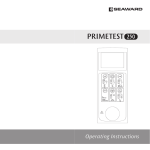
SafetyPAT Plus
C
A
B
P/N:110401103864
Test Instrument Solutions
SafetyPat Plus Instructions
A.Features – SafetyPat Plus
The SafetyPat Plus is a handheld battery powered unit suitable for carrying out electrical safety tests.
Features include:
●
110v, 230v,& 415v Equipment ( 110 & 415v by optional adaptors )
●
Class 1 Equipment
●
Class 2 Equipment
●
IT Equipment
●
Earth Bond Test 0.1 and 0.5 of an ohm preset values
●
Insulation Test
●
Leakage Test portable/handheld =0.75mA, other class 1= 3.50mA
●
Socket Test
●
Long Extension Lead Test up to 0.5 of an ohm
●
Polarity Test
●
IEC Cord Test
●
With displayed Results & Pass or Fail Indication
●
Tests Surge Protected Items, 250V Insulation Test
●
Can store up to 1000 results
1
B.Unpacking Inspection & Standard Accessories
We have taken extra care to ensure you are delighted with your Pat Tester and each unit has been calibrated
and fully checked, before dispatch. Please check your unit fully upon opening and in the unlikely event,
anything is missing report this immeadiately
Open the package case and take out the Meter. Check the following items carefully to see any missing or
damaged components
*
SafetyPat Plus
1 piece
*
Instruction Book
1 piece
*
Test Lead IEC
1piece
*
Crocodile Clip
1 piece
*
Earth Wander Lead
1 piece
*
Test Probe
1 piece
*
Shoulder Strap
1 piece
*
Batteries Alkaline AA 1.5V
8 piece
*
Calibration Certificate
1 piece
*
Mains Lead
1 piece
2
C.Safety
Please read the following instructions carefully before use
z
Please inspect your SafetyPat Plus and accessories before use.
Do not use the Unit and accessories if
they are damaged in anyway.
z
Replace the batteries as soon as the battery indicator “
”Appears.
Using the unit with a low battery
may result in incorrect readings
z
Should you suspect a fault has developed with your unit, check the batteries before returning the unit to
your place of purchase. Under no circumstances should you open the case and attempt a repair as this
will void your Warranty and Calibration Certificate
z
Do not use or store the unit outside of its Environmental or Operating Capabilities
z
The unit should only be repaired or re-calibrated by ourselves or an authorized agent
z
The batteries supplied with the unit are not Re-chargeable and Must not be re-charged. However
suitable re-chargeable batteries can be used,provided they are charged outside the tester,a mains lead
is also provided for use,independent of the batteries.
z
When fitting the batteries into the unit please ensure you have correctly identified the polarity. Incorrect
polarity could be dangerous and could cause damage to your tester, which will affect your warranty.
3
Warning Signs used within this manual
Danger-Caution, risk of electric shock. Indicates instructions must be followed to avoid danger to
persons or equipement
Warning-Caution, risk of danger.
The operating instructions must be adhered to in order to avoid
danger。
D.Product Outlook & Diagrams
Diagram 1; Shows layout of instrument
4
Diagram 2; shows layout on Front & Rear Panels
1.
Power On/Off
Press
to switch on/off the meter
A 13A Mains Socket on Front Panel
B
(A) button (Diagram 1) Class I button
C
(B) button (Diagram 1) Class II button
D
(C) button (Diagram 1) Cord, IEC & Extension Lead button
E
LCD Display (Diagram 1)
F
Socket on rear end panel for earth test lead ( Diagram 2)
G
Socket on end panel for main cord testing (Diagram 2)
E.Testing Procedures
1:
Press (A) button,CLASS-I Appliance Test, also for “ I.T.” Equipment (computers etc.)
2:Press (B) button,CLASS-II Appliance Test
3:Press (C button,Cord / Extension Lead Test
5
4:Press any other buttons matrix without functions.
5:Automatic switch off after approximately 2 minutes if no any buttons are pressed
6:The auto switch off is disabled during a power socket test
1.
Power On/Off
Press
2.
to switch on/off the meter
Zero Clearing
Connect the zeroing plug, Long press “Class I” button for 3 seconds and then release it, the meter will check
whether the connection is correct. If it does, the meter will clear the resistance values of connection cable and
the one inside the meter. This allows you to use longer earth leads
3. 500V / 250V DC Voltage and Auto Save Setup
Long press “Class II” button for 3 seconds, then release it, the meter will go into DC voltage setup interface.
The first line is to display “SET”, “DC” on the second line and the current voltage value “250V” or “500V” on the
third line. Use “Class I” button to set DCV to 500V and “Class II” button to go for 250V for surge protected
items. Then press “CORD” button to save the settings and go into auto data save interface. The first line is to
display “SET”, “AUTO” on the second line and “SAVE” on the third line. Pushing “Class I” button to set to
“SAVE 0” non-automatic save and “Class II” button to go to “SAVE 1” automatic save. Then press “CORD”
button to save the settings (the settings are still kept even after power failure), the meter then will exit setting
mode and go into measuring status.
6
4. Data Access
Long press “CORD” button for 3 seconds, then release it, LCD will display the last recorded data, One second
later, the display zone on the last line will show the current data number alternately. The maximum data is up
to 1000 pieces. Use “Class I” to increase the recording number by 1 and “Cord” to decrease by 1. Long
pressing “Class I” button to increment or “Cord” to decrement the recording number progressively. Finally use
“Class II” button to exit data access mode and go into measuring status.
When there is no any saved data, LCD will display “NO SAVE ----” for 2 seconds and then exit the data access
mode.
5. Default Data Clearing and Cancel Auto Save WARNING This action will remove
data!!!!!!
Press the meter power on, then simultaneously press and hold “Cord” buttons, then the meter will clear all the
recorded data and disable the auto save function.
Insulation Test Voltage is now set at DC500V.
6. Flash Indication - Results
6.1 Under Earth Continuity test, solid “√” shows if protective conductor resistance falls within 0.01Ω~0.1Ω; “√”
flashes for the resistance value between “0.10Ω~0.50Ω” and “×” displays for the range between
“0.51Ω~19.9Ω”.
7
6.2 Under CLASS I Earth Leakage test, solid “√” shows when leakage current values are between
0.01~0.75mA, “√” flashes for readings within 0.75~3.5mA and “×” appears if it is between 3.5~10.5mA.
6.3 With Earth Continuity, Insulation Resistance and Earth Leakage tests all completed, the meter would show
“FAIL”if one of these items displays “×”. If the meter displays “PASS”, and at the same time one or two “√” flash,
the word “PASS” will also flash together. See Table 1 for reference.
SEE TABLE 1
7. Testing a Class 1 Equipment
Plug the appliance into the mains socket (A).
Plug the earth test lead into the rear socket
Connect the earth test crocodile clip/probe to an exposed earthed metal part on the appliance
switch on the appliance ensure it is in the “on” position. Press Class 1 button
(F.)
If there is a
The Earth Test will be carried
out, if the test result is a SOLID PASS, this indicated the result is less than 0.1 of an ohm. However if the PASS
is FLASHING this indicates the result is between 0.1. and 0.5 of an ohm, this could be due to the length of the
lead connected to the appliance. If the appliance under test has only a short lead then this result must be
investigated. Both the Insulation Test and the Earth Leakage Test, will follow.
If the test is an overall PASS then AutoSave the result or write the results down, before testing the next
appliance. In the case of the Earth Leakage result, for portable handheld equipment the maximum leakage
8
value must not exceed 0.75mA for other class1 equipment such as heating equipment etc the Earth Leakage
result must not exceed 3.50mA as outlined in the” Code of Practice for in-service inspection & Testing of
rd
Electrical Equipment 3 Edition, TableV.3 Page 110”. The tester from 0.01 to 0.75mA will indicate a PASS,
from 0.75mA to 3.50mA the PASS will flash which will indicate that should the appliance under test be a
heating appliance or an appliance other than portable or handheld that the appliance has PASSED the Test.
However if the appliance, is not a heating appliance and is a portable or handheld appliance then the
maximum Earth Leakage allowed is 0.75mA therefore the appliance should be treated as a FAIL
Should the wording LO-LOAD appear after the Earth Test has finished it indicates the appliance is not
switched on, turning on the switch of the appliance will automatically start the tester completing the Insulation
Test and Leakage Test. If the appliance switch was on, then simply press the Class I button to complete the
outstanding tests
If the result is a FAIL on the Earth, ensure that you are not connected to a piece of metal which has been
painted or a metal screw that’s only into plastic and not connected to earth. In the case of an earth path which
has been painted try using the probe to penetrate the painted area then repeat the test. The pass band on the
SafetyPat Plus is set up to and including 0.5 of an ohm, a failure could also be because you are testing an
appliance with a long lead, have a resistance greater than 0.5 of an ohm, this would obviously be why the
appliance/ extension lead has failed the Earth Test.
9
Likewise if a reading was produced from testing an item with a very short lead, of 0.5 of an ohm, then this
should be investigated, as the competent person doing the test must realise that the result would have been
less than 0.1 of an ohm.
Having a FAIL on insulation with a class 1 appliance, where the Pass band is set at 1Mohm usually indicates
the appliance has an insulation fault, however depending on the appliance under test this sometimes can be
caused, when a heating element in the appliance,is damp or dusty. Cleaning the appliance, or connecting the
appliance to the mains, or repeating the test may improve the insulation reading.
Sometimes when testing insulation you will see the words LO LOAD appear on the display, this may mean that
the appliance has a very low load, a blown fuse or the most common fault is, that you forgot to switch the
appliance on, check all three, and re-test by pressing Class 1 button
Having a FAIL on Earth Leakage means that the leakage is greater than 3.50mA If the piece of equipment
under test was “portable/handheld” the maximum earth leakage must not exceed 0.75mA for “Other” class 1
equipment this must not exceed 3.50Ma
If in doubt check with the equipment manufacturer.
10
8. Testing a CLASS-2 Appliance
Plug the appliance into the panel main socket (A). Plug the earth test lead into the socket (F) on the
rear end panel. Connect the earth crocodile clip or probe to any exposed part on the appliance (See
Diagram 4)
Press ClassII button , ensure that appliance is switched on, the tester will display the Insulation Test
result if the result is greater than 2Mohms this will be indicated as a pass, a normal reading
on most
appliances will be 19.99Mohms. The Earth Leakage test will then be carried out automatically, providing the
result is 0.25mA or less then the result will be displayed as a PASS
If after pressing Class II button
the wording LO-LOAD appears on the display, this means either the
11
appliance has a genuine low load, a blown fuse or more than likely, you forgot to switch the appliance on,
check all three, then press Class II button again to carry out the test
Should the Insulation Test FAIL, then the result will be less than 2Mohm, the most likely fault will be that the
appliance is faulty, if the appliance has a motor the cause may be because the motor needs new bushes,
carrying out a repair may be a solution, before re-testing the appliance
If the Earth Leakage Test FAILS then this would mean that the earth leakage is above 0.25mA. If in doubt
check with the appliance manufacturer
9. Testing a IEC Mains Cord
Plug the mains lead under test into socket (A) and the IEC connector into socket (G) on the rear of the tester.
Press the Cord button C the tester will carry out the Earth Bond Test, Insulation Test & Polarity Test,
Displaying results for Earth & Insulation, in the case of Polarity, the result will be either Pass/ Fail
Should a Fail result appear check the wiring of the IEC Mains Cord, re-test
10. Testing an Extension Lead IMPORTANT Ensure you uncoil any extension
leads
Plug the extension lead into socket (A) on the tester. Use the short IEC Lead that came with your
12
tester and plug it into the end of your extension lead, connect the IEC end into socket (G) of the
tester, to form a loop, THEN follow the testing procedure as described above for IEC Mains Cord.
Should a Fail result appear firstly check the wiring of the extension lead at both ends. The
Extension lead could have failed due to the length of the extension lead, for instance a 50M
extension lead would produce a result in excess of 0.5 of an ohm and therefore a Fail
11. Checking a mains power outlet
Connect the power cord IEC connector,supplied, into the unit socket (G) and plug the mains plug of the power
cord into the mains power outlet to be tested.
(See Diagram 6 connection)
If the socket outlet is correct this will be indicated as LN,LE,NE ok PASS
If the result is a FAIL for instance if Live and Neutral in the socket is reversed
or there is a fault with the protective earth connection this will be indicated :
13
“LN√,LE×,NE×”
If there is a fault with the Neutral connection this will be indicated:
“LN×,LE √,NE×”
If the mains socket wiring is correct the display will be indicated:
“LN√,LE √,NE√
12. Maintenance
Replacing the Batteries
When the low battery warning is displayed
you need to replace the batteries.
Battery replacement is as follows. (We recommend the use of “Alkaline Batteries”)
1) Disconnect any leads from the Tester before replacing the batteries.
2) Power off the unit
3) Loosen the screw of the battery compartment and then remove the old batteries
4) Use 8 x AA cell LR14 batteries (Alkaline)
5 Important, it is essential that you ensure
polarity "+" and
"-"
of each
battery in the unit
6) Then tighten the screw on the battery cover, turn on the unit and check that the Lcd Display comes on, if the
display does not come on re-check the polarity of the batteries, if this is ok roll your hand over the batteries, so
they rotate, this is to ensure a good contact, sometimes a protective film is applied to new batteries which can
prevent good contact when first fitted
14
We recommend that if the unit is not used for over 2 to 3 weeks that the batteries are removed from the unit,
for storage
Any contamination of the battery contacts or compartment should be cleaned with a dry cloth.
13. Cleaning
Clean only with a dry cloth; do not use solvents.
14. Calibration & Repairing
This unit is calibrated to a specified accuracy at our factory, either the manufacturer or an authorized
service agent must repair/ re-calibrate the instrument. We recommend a one year re-calibration cycle. Any
repair of the unit must be carried out by Test Instrument Calibrations or an authorized agent, if a repair is
carried out by a non-approved agent then this may void any warranty.
15 Warranty
The Warranty period is 2 years from date of purchase, proof of purchase is required in the form of a copy of
nd
your original invoice, before any repair is carried out under this warranty.To obtain your 2 year warranty, it
is a condition to have your instrument Calibrated at the start of year two by Test Instrument Calibrations,
you will then receive, years two guarantee. This does not affect your rights under your 12 month warranty.
15
Table 1
CLASS I
Show “PASS/FAIL”
Earth Continuity
Insulation Resistance
Earth Leakage
“√”
“√”
“√”
“PASS”
“√”flash
“√”
“√”
“PASS” flash
“×”
“√”
“√”
“FAIL”
“√”
“×”
“√”
“FAIL”
“√”
“√”
“√”flash
“PASS” flash
“√”
“√”
“×”
“FAIL”
“√”flash
“√”
“√”flash
“PASS” flash
16
TIS Technical Specifications
TIS SafetyPat Plus
Function
Insulation
Resistance
Earth
Continuity
Main Technical Parameters
Range
Accuracy
Technical parameter
0.20MΩ~19.99MΩ
±5%+3
Test Voltages 500V
-
(R=500KΩ):
0.20MΩ~19.99MΩ
±5%+3
TEST TIME 5S
Test Voltages 250V
-
(R=1KΩ): 2mA
CLASS I
-
1MΩ PASS
CLASS II
-
2MΩ PASS
CORD
-
1MΩ PASS
0.00Ω~19.99Ω
±5%+3
>1mA
( R<2Ω )Test Current >200mA
17
0.01Ω~0.1ΩShow solid PASS
0.1Ω~0.5ΩPASS
0.51Ω~19.9Ω
Test Voltages
Test Time
must flash
Show Fail
5v DC
5S
Test Voltages 50V rms,
0.10~10.5mA
±5%+3
Test Time
5S
Test Frequency
50HZ
0.01~0.75mA Show solid PASS
Earth Leakage
CLASS I
-
0.75~3.5mA PASS
flash
3.5~10.5mA
CLASS II
Cord
Correct
-
must
Show Fail
0.01~0.25mA Show solid PASS
0.25~10.50mA Show Fail
√PASS
18
open circuit,
short circuit,
×FAIL
transposition
Voltage test
GOOD
Show"LN√,LE √,NE√”
GROUND(NG)
Show“LN√,LE×,NE×”
NE(NG)
Show“LN×,LE √,NE×
Batteries
LOW Voltage
LR6
AC220V±15%
1.5V*8
≤9.0v
7. Supplied Power Adaptor
Specifications:
1. Input Voltage Rating: 100-240 Vac
2. Rated Input Frequency: 50/60Hz
3. Rated Output Voltage: 12Vdc
4. Rated Output Power: 24W
5. Max. Output Current: 2000mA
19
4. Environmental Condition
Operating temperature range 0℃ to 40℃,without moisture condensation。
Storage temperature range 0 to 40C
Batteries must be removed prior to storage。
20