1
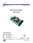
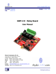
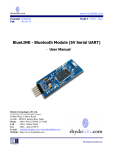
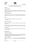
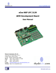
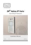
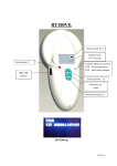
www.rhydolabz.com Document : Datasheet Date : 25-Feb-10 Model # : RFID - 1321 RFID Reader – RS-232 User Manual Rhydo Technologies (P) Ltd. (An ISO 9001:2008 Certified R&D Company) Golden Plaza, Chitoor Road, Cochin – 682018, Kerala State, India Phone : 0091- 484-2370444, 2371666 Cell : 0091- 99466 70444 Fax : 0091 - 484-2370579 E-mail : [email protected], [email protected] WebSite : http://www.rhydolabz.com We bring the world to you.. www.rhydolabz.com The rhydoLABZ RFID reader reads EM4100 family transponder tags that are brought in proximity to the reader and output the unique tag identification number through serial port @9600 bps. The reader output 12 byte including one start, stop byte and 10 unique data byte. The start byte and stop byte are used to easily identify that a correct string has been received from the reader. The middle ten bytes are the actual tag's unique ID. Vertical and horizontal parity checking has been done in card reading algorithm to ensure data integrity. One status LED is provided to indicate card detection. The normal detection range is 10-15CM for Card Type TAGs. The RFID Reader (as well as the RFID tags sold by rhydoLABZ) uses the EM4102 protocol. Any other tags that also use the EM4102 protocol can be used with the rhydoLABZ RFID reader. PRODUCT FEATURES Low-cost method for reading passive RFID EM4100 family transponder tags Reading Distance 10-15CM of the reader (Depends on card shape) 125 KHz read frequency 9600 Baud RS-232 Serial interface Standard 2.54mm Pitch Bergstrip connector Bread Board compatible Low power Requirement 7-9V@ 100mA Small Size Built in Antenna No components at PCB bottom side (easy to stick to any surface like wood, glass etc.) Designed by RHYDO Status LED for card detection On-Board Power LED We bring the world to you.. www.rhydolabz.com KEY SPECIFICATIONS Power requirements : 7 to 9V DC Current Requirement : <110 mA Communication : RS-232 Serial at 9600 baud (8N1) Dimensions : 63mm x 98mm x 5 mm Operating temp range : -40 to +185 °F (-40 to +85 °C) PROTOCOL All communication is 8 data bits, no parity, 1 stop bit, non-inverted, least significant bit first (8N1). The baud rate is configured for 9600 bps, a standard communication speed supported by any microprocessor or PC, and cannot be changed. The rhydoLABZ RFID Reader Module initiates all communication. The rhydoLABZ RFID Reader Module can connect directly to an RS232-compatible interface (PC) or to any compatible UART by using an external level shifter. When the RFID Card Reader is active and a valid RFID transponder tag is placed within range of the activated reader, the unique ID will be transmitted as a 12-byte printable ASCII string serially to the host. The format is as shown below: Start Byte (0x0A) Tag ID Digit 1 Tag ID Digit 2 Tag ID Digit 3 Tag ID Digit 4 Tag ID Digit 5 Tag ID Digit 6 Tag ID Digit 7 Tag ID Digit 8 Tag ID Digit 9 Tag ID Digit 10 Stop Byte (0x0D) The start byte and stop byte are used to easily identify that a correct string has been received from the reader (they correspond to a line feed and carriage return characters, respectively). The middle ten bytes are the actual tag's unique ID. Example: Consider a tag with a valid ID of 0A1F4320B0 (10 bytes). The bytes sent by the reader will be: $0A, $30, $41, $31, $46, $34, $33, $32, $30, $42, $30, $0D We bring the world to you.. www.rhydolabz.com INTERFACING DETAILS When the RFID Card Reader is powered, the module will be in active mode and the current consumption of the module will increase. A visual indication of the state of the RFID Card Reader is given with the on-board LED’s. When the module is successfully powered-up, the Green LED (PWR) will be ON. When the module is in an active state and the antenna is transmitting, the Red LED (STS) will be blinking. The face of the RFID tag should be held parallel to the front or back face of the antenna (where the majority of RF energy is focused). If the tag is held sideways (perpendicular to the antenna) you may have difficulty getting the tag to be read. Only one transponder tag should be held up to the antenna at any time. The use of multiple tags at one time will cause tag collisions and confuse the reader. Actual distance may vary slightly depending on the size of the transponder tag and environmental conditions of the application. PIN DESCRIPTION PIN PIN NAME DETAILS RXD RECEIVE Pin for Data Reception GND GROUND Ground level of Power supply TXD TRANSMIT Pin for data Transmission DC CHARACTERISTICS At VCC = +9.0V and TA = 25ºC Parameter Symbol Test Conditions Specification Min. Typ. Max. Unit Supply Voltage VCC --- 6.5 9.0 10 V Supply Current, Active ICC --- --- 100 --- mA We bring the world to you.. www.rhydolabz.com INTERFACING WITH PC K1 5 9 4 8 3 7 2 6 1 Db9 female We bring the world to you.. www.rhydolabz.com DIMENSIONS (mm) We bring the world to you.. www.rhydolabz.com ABSOLUTE MAXIMUM RATINGS Condition Value Operating Temperature -40ºC to +85ºC Storage Temperature -55ºC to +125ºC Supply Voltage (Vcc) +6.5V to +10V Ground Voltage (Vss) 0V Stresses above those listed under “Absolute Maximum Ratings” may cause permanent damage to the device. Exposure to maximum rating conditions for extended periods may affect device reliability. GETTING STARTED Connect DB9 Connector Connect a DB9 female connector to the RFID reader board as per the circuit diagram given. Connect RS232 Cable Connect the serial cable to the DB9 Female connector. Connect the other end to the ComPort of the PC. Power Supply Connect the power Supply (7-9V DC) to the power supply input pins. Led Indication When the module is successfully powered-up, the Green LED (PWR) will be ON and the Red LED (STS) will blink two times. When the module is in an active state and the antenna is transmitting, the Red LED (STS) will be blinking. Baud rate The Baud rate supported by the reader is 9600. Make sure the host system is set to the supported baud rate. We bring the world to you.. www.rhydolabz.com Testing with a PC 1. 2. 3. Connect the RFID Reader to a PC Com port using an RS-232 Cable and Power it Up. Create a HyperTerminal (Windows tool for serial port communications) window with Baudrate 9600 and connect it to the ComPort to which the reader is connected. Keep an RFID card near the reader antenna and you could see the transmitted 10-byte code in the hyper terminal window. Terminal Window on PC where RFID Reader is connected We bring the world to you.. www.rhydolabz.com PC INTERFACE SOFTWARE FOR RFID READER Download setup file from www.rhydolabz.com/documents/rfid/rfid_reader.zip Install the setup file in your PC. Once the installation is completed, open the application from StartMenu-Programs-Rhydolabz-Rfid Reader Connect the Rfid Reader to the Com port of the PC using an RS-232 Cable and Power it Up. Select the Comport* (in the application software) to which Rfid Reader is connected and Press the “Connect” button. Show the RFID Tag near the Reader antenna and the software displays the 10-byte code. * If you are connecting the reader using a Serial to USB Convertor and the comport number does not appear in the software, re-assign the Comport to an available one.(Can be done in Device Manager- Comport-Properties) We bring the world to you.. www.rhydolabz.com RFID SYSTEMS AND APPLICATIONS Radio Frequency Identification (RFID) is a generic term for non-contacting technologies that use radio waves to automatically identify people or objects. There are several methods of identification, but the most common is to store a unique serial number that identifies a person or object on a microchip that is attached to an antenna. The combined antenna and microchip are called an "RFID transponder" or "RFID tag" and work in combination with an "RFID reader" (sometimes called an "RFID interrogator"). Just like a bar code, a transponder tag carries data about its host. When interrogated by a reader, it responds with that data over a radio frequency link. The transponder could be really simple, like those in clothing price tags, consisting of just an antenna and diode. When irradiated, the diode rectifies the incoming carrier and the frequency-doubled signal is radiated back to the reader which responds with an alarm if you try to leave the store without paying for the product. There are two major types of tag technologies. "Passive tags" are tags that do not contain their own power source or transmitter. When radio waves from the reader reach the chip’s antenna, the energy is converted by the antenna into electricity that can power up the microchip in the tag (known as "parasitic power"). The tag is then able to send back any information stored on the tag by reflecting the electromagnetic waves. "Active tags" have their own power source and transmitter. The power source, usually a battery, is used to run the microchip's circuitry and to broadcast a signal to a reader. Due to the fact that passive tags do not have their own transmitter and must reflect their signal to the reader, the reading distance is much shorter than with active tags. However, active tags are typically larger, more expensive, and require occasional service. Frequency refers to the size of the radio waves used to communicate between the RFID system components. Just as you tune your radio to different frequencies in order to hear different radio stations, RFID tags and readers must be tuned to the same frequency in order to communicate effectively. RFID systems typically use one of the following frequency ranges: low frequency (or LF, around 125 kHz), high frequency (or HF, around 13.56 MHz), ultra-high frequency (or UHF, around 868 and 928 MHz), or microwave (around 2.45 and 5.8 GHz). The RFID Card Reader from Rhydolabz is designed specifically for low-frequency (125 kHz) passive tags. RFID (Radio frequency identification) systems use data strings stored inside RFID tags to uniquely identify people or objects when they are scanned by an RFID reader. These types of systems are found in many applications such as passport protection, animal identification, inventory control systems, secure access control systems, robotics, navigation, inventory tracking, payment systems, and car immobilization. Because passive tags require a strong RF field to operate, their effective range is limited to an area in close proximity to the RFID reader. The distance over which the RFID tag is usable is affected by such things as the tag shape and size, materials being used in the area near the reader, and the orientation of the reader and tag in respect to each other and in their operating environment. The smaller a tag, the closer it must be to the reader to operate. Each transponder tag contains a unique identifier (one of 1,099,511,627,776, possible combinations) that is read by the RFID Reader Module and transmitted to the host via a simple serial interface. We bring the world to you.. www.rhydolabz.com TECHNICAL SUPPORT If you are experiencing a problem that is not described in this manual, please contact us. Our phone lines are open from 9:00 AM – 5.00 PM (Indian Standard Time) Monday through Saturday excluding holidays. Email can be sent to [email protected] LIMITATIONS AND WARRANTEES This product is intended for personal or lab experimental purpose and in no case should be used where it harmfully effect human and nature. No liability will be accepted by the publisher for any consequence of its use. Use of the product software and or hardware is with the understanding that any outcome whatsoever is at the users own risk. All products are tested for their best performance before shipping, still rhydoLABZ is offering One year Free service warranty (Components cost + Shipping cost will be charged from Customer). DISCLAIMER Copyright © Rhydo Technologies (P) Ltd All rights are reserved. Reproduction in whole or in part is prohibited without the prior written consent of the copyright owner. The information presented in this document does not form part of any quotation or contract, is believed to be accurate and reliable and may be changed without notice. Rhydo Technologies (P) Ltd. (An ISO 9001:2008 Certified R&D Company) Golden Plaza, Chitoor Road, Cochin – 682018, Kerala State, India Phone : 0091- 484-2370444, 2371666 Cell : 0091- 99466 70444 Fax : 0091 - 484-2370579 E-mail : [email protected], [email protected] WebSite : http://www.rhydolabz.com We bring the world to you..