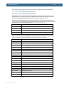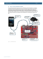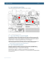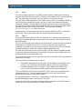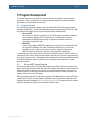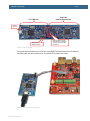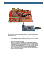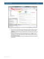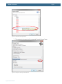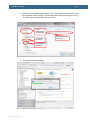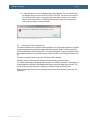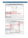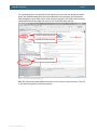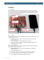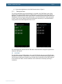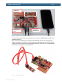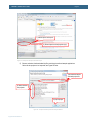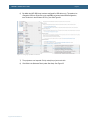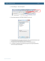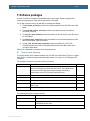
1
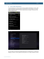
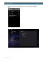
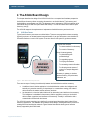
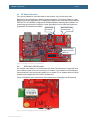
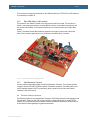
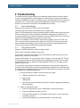
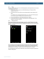
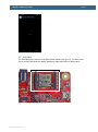
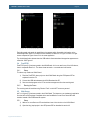
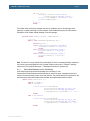
AOAA Kit - User’s Guide
Page 36
After this, Flash Magic is ready to be used. Start by selecting the correct device, LPC1769 in this case.
Then select the correct COM port. Note that the AOAA board contains a UART-to-USB bridge.
UART#0 of the LPC1769 is connected to this. See section 3.5 how to install the driver for this bridge
chip. When the AOAA board is connected via a USB cable (J16, mini-B USB connector) to the PC a
(virtual) COM port will be created. It is this COM port that shall be selected. Baud rate shall be set to
“57600”, Interface to “None (ISP)” and Oscillator to “12”. Sometimes the baud rate must be lowered to
“38400” to get it working. If there is problem to communicate with the board, test to lower the baud rate
first.
After this, select the hex/binary file to be downloaded. Finally press the Start button to start
downloading the application.
Figure 23 – Flash Magic
5.1.2
SWD/JTAG Program Download
This section describes how to download an application with the help of LPCXpresso IDE and the LPCLINK. For other development environments (IDEs), see respective documentation about flashing.
The first thing is to create an LPC-LINK, the SWD/JTAG interface that the LPCXpresso IDE uses. It is
a relatively simple process. Start with an LPCXpresso LPC1769 board. Separate the LPC-LINK side
from the target side either by physically cutting the board or by using a soldering iron and remove all
solder bumps that form the connection between the two sides. See Figure 24 for an illustration. The
reason why an LPCXpresso LPC1769 board is recommended is that not all LPCXpresso boards have
the same connections between the two sides. The LPC1769 board is very simple to separate with a
soldering iron.
Copyright 2012 © Embedded Artists AB