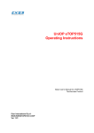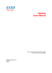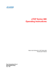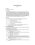
1
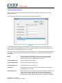
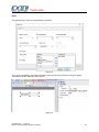
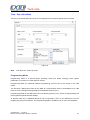
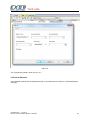
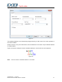
Tech-note KNX TP/IP Communication Driver for JMobile This Technical Note contains the information needed to connect the system to KNX networks Exor International S.p.A. ptn0408 Ver. 1.03 Tech-note Copyright 2014 EXOR International S.p.A. – Verona, Italy Subject to change without notice The information contained in this document is provided for informational purposes only. While efforts were made to verify the accuracy of the information contained in this documentation, it is provided “as is” without warranty of any kind. Third-party brands and names are the property of their respective owners. www.uniop.com ptn0408-3.doc - 7.01.2015 KNX TP Communication Driver for JMobile 2 Tech-note Contents KNX TP/IP Driver...................................................................................................................... 4 Protocol Editor Settings ................................................................................................ 5 Communication parameters ......................................................................................... 6 Tag Import ................................................................................................................... 7 Polling Attribute............................................................................................................ 9 Special Data Types .................................................................................................... 10 Dimming function ....................................................................................................... 11 Time ...................................................................................................................... 13 Date ...................................................................................................................... 14 Time – Day of the Week ............................................................................................. 15 Programming Mode.................................................................................................... 15 Individual Address ...................................................................................................... 16 Communication Status ............................................................................................... 18 ptn0408-3.doc - 7.01.2015 KNX TP Communication Driver for JMobile 3 Tech-note KNX TP/IP Driver KNX is the association that promotes the KNX communication standard, designed for applications in home and building automation systems. The KNX standard, approved as European Standard EN 50090, EN 13321-1, is based on the communication stack of EIB with some extensions. EIB is the acronym for European Installation Bus. Additional information and further details can be found in the KNX web site www.knx.org. The network communication media supported by the HMI panels are: TP-1: twisted pair, type 1, which corresponds to a bus line operating at 9600 bit/s. IP: network connection via TCP/IP over Ethernet network. Note: Connection to KNX systems in TP Mode requires the optional KNX communication module PLCM02. Verify the suitable version of communication module for your HMI model. The EIB is an event-driven decentralized automation system. The information to be transmitted over the bus is organized in “telegrams” sent by a source to one or more destination devices. The bus line of EIB systems carries both data and power for the devices. The data is modulated over the DC voltage of the power supply. HMI panels are not powered from the network and they still need the usual power supply. The planning, design and commissioning of KNX installations are normally done using the ETS configuration software. This software tool is supplied by the KNX organization. ETS is a registered trademark of KNX. This document contains the information required to use ETS in combination with the HMI panels. All KNX compliant devices come with a device descriptor delivered as a file to be imported in the configuration tool. The model adopted by HMIs corresponds to a KNX device with no objects. For what concerns the ETS, the only function supported by the HMI panels is the device physical address assignment. ptn0408-3.doc - 7.01.2015 KNX TP Communication Driver for JMobile 4 Tech-note Protocol Editor Settings Add (+) a driver in the Protocol Editor and select the protocol called “KNX TP/IP” from the list of available protocols. The protocol parameters can be selected from the dedicated dialog boxe: Figure 1 The Individual Phisical Address can be assigned on the HMI screen at the first download of the project configured for the KNX protocol. This is the Phisical Address that identifies the panel in the KNX network. The default address value is: 15.15.255. Please note that, as any other KNX device, also the HMI device must have unique Individual Address in the KNX network and it must correspond to the real point in the network where the HMI device is connected. Media Allows the selction of the Media, select TP to connect to the KNX network using the optional KNX communication module PLCM02. Select IP to connect to the KNX network via TCP/IP. IndividualAddressH Phisical Address High Part (Area) IndividualAddressM Phisical Address Medium Part (Line) IndividualAddressL Phisical Address Low Part (Device) PLC Models KNX telegram can have three or two stage addressing, select model corresponding to your needs Search Interval (s) When media is set to IP, the KNX driver will re-evaluate the network with period “Search Interval” (default: 300 seconds). On searching the network, the KNX driver will discover the tunneling endpoints that are available at that time. Endpoints will therefore be registered as possible ptn0408-3.doc - 7.01.2015 KNX TP Communication Driver for JMobile 5 Tech-note sources / destinations for group address operations. Depending on endpoints settings or endpoints temporary unavailability the available sources / destinations for group address operations may vary. Thus the capability for the KNX driver to re-evaluate periodically its knowledge about the network. Communication parameters The communicaton parameters can be selected from the dedicated dialog boxe: Figure 2 Polling Time Defines how often the tags with Polling attribute enabled are requested to the network (seconds). Trasmission Rate Defines the interval of time between two consecutive write operations performed by the operator panel (milliseconds). ptn0408-3.doc - 7.01.2015 KNX TP Communication Driver for JMobile 6 Tech-note Tag Import The KNX TP/IP driver supports the Tag import facility.The import filter accepts symbol files with extension “.esf” created by the ETS programming tools. The ETS configuration software can export the database information related to group addresses. To export database information select “Extract data” from the File menu of ETS software. Figure 3 Select the option “Export to OPC Server” to export data in “.esf” format. Clicking on “Export...” creates the “.esf” file to be imported in the Tag Editor. Figure 4 To import tags from the “.esf” file created, select the communication driver in the Tag Editor and click on the “Import tag” button to start the import process. ptn0408-3.doc - 7.01.2015 KNX TP Communication Driver for JMobile 7 Tech-note Figure 5 Locate the “.esf “ file and confirm with OK. The tags present in the imported document are listed in the tag dictionary.The tags can now be added to the project using the “Add tags” button as shown in Figure 6. Figure 6 ptn0408-3.doc - 7.01.2015 KNX TP Communication Driver for JMobile 8 Tech-note Polling Attribute The Polling attribute is associated to each individual tag (corresponding to a KNX group address). This attribute can be found it in the “Edit tags” window, as shown in Figure 7. Figure 7 ptn0408-3.doc - 7.01.2015 KNX TP Communication Driver for JMobile 9 Tech-note Special Data Types The list of special data formats supported by this implementation of the KNX protocol is the following: Data Types Memory Type Bit 1 Bit Controlled 3 Bits Controlled Octet, Unsigned BIT 1BIT 3BIT OU Octet, Signed OS 2 Octets, Unsigned 2 Octets, Signed 2 Octets, Float Time Date String 2OU 2OS 2OF TIM DAT STR 4 Octets, Unsigned 4 Octets, Signed 4 Octets, Float Access Uncertain (1 byte) Uncertain (2 Bytes) Uncertain (3 Bytes) Uncertain (4 Bytes) 4OU 4OS 4OF ACC U1 U2 U3 U4 KNX Datapoint Type 1.0xx N/A 3.007 4.00x 5.00x 17.001 18.001 6.001 6.010 7.0xx 8.0xx 9.0xx 10.001 11.001 16.000 16.001 12.001 13.0xx 14.0xx 15.000 Uncertain Uncertain Uncertain Uncertain Some KNX Datapoint Types can be converted using the “Scaling” functionality, available for all the tags. In Figure 8 you can see an example of scaling conversion for Percent values of dimmer actuators (Datapoint Type 5.001 DPT_Scaling). Applying this Scaling conversion, the “0/0/1 % Value” tag manage values in range 0÷100 instead of standard range 0÷255 of Unsigned Octet. Figure 8 ptn0408-3.doc - 7.01.2015 KNX TP Communication Driver for JMobile 10 Tech-note Dimming function To operate a dimming function in JMobile, you need to work using the 3 Bits Controlled data type. Actually this is a 4 bit data where the 1st bit is used to determine if increment or decrement the value and the remaining 3 bits determines the percentage of dimming applied. The Tag will represent a fixed percentage value (from 0% to 100%) of increasing or decreasing of a particular device value. Figure 9 The table below reports the action performed for each value assumed by the Tag. For example, to increase the dimmed value of 25% it is necessary to write into the Tag that manages the dimming the binary value “1011”, wich in decimal code, corresponds to “11”. Direction 0 0 0 0 0 0 0 1 1 1 1 1 1 1 ptn0408-3.doc - 7.01.2015 KNX TP Communication Driver for JMobile Data 001 010 011 100 101 110 111 001 010 011 100 101 110 111 Action Down 100% Down 50% Down 25% Down 12% Down 6% Down 3% Down 1% Up 100% Up 50% Up 25% Up 12% Up 6% Up 3% Up 1% 11 Tech-note As mentioned before to increase the dimmed value by 25% it is necessary to write 11 in the corrisponding Tag, To do this a Write Tag action programmed as shown in the Figure 10 must be created. Figure 10 ptn0408-3.doc - 7.01.2015 KNX TP Communication Driver for JMobile 12 Tech-note Time The Time data type requires a special data conversion. Figure 11 The correct visualization of the time information from this tag can be achieved using the widget dedicated to handle “Time” data source. Figure 12 Note: In the “DateTime” widget it is important to set properly the “Time Spec” property in order to avoid the influence on the visualization of the HMI clock timezone and DST settings; Select Number format properly. Note: Write operation from HMI to KNX network will be executed only with “No Day” information. ptn0408-3.doc - 7.01.2015 KNX TP Communication Driver for JMobile 13 Tech-note Date The Date data type requires a special data conversion. Figure 13 The correct visualization of the date information from this tag can be achieved using the widget dedicated to handle “DateTime” data source. Figure 14 ptn0408-3.doc - 7.01.2015 KNX TP Communication Driver for JMobile 14 Tech-note Time – Day of the Week The Day of the Week data type is part of Time telegram and requires a special data conversion. Figure 15 Note: This object is in read-only mode Programming Mode Programming Mode is a special device operating mode that allows changing some system parameters. It is common to most KNX TP devices. Programming Mode for Individual Address programming via ETS can be set directly in the HMI device. The first time a HMI project made for the KNX TP communication driver is downloaded to an HMI panel, the unit is assigned the specified Phisical Address (see Figure 1). Programming Mode for the HMI panel can be enabled by placing on the screen a widget assigned to the Programming Mode internal variable. At present there are no database files that can be imported in ETS, so the HMI device can’t be programmed using ETS software. The Programming Mode is available only for future functionalities. ptn0408-3.doc - 7.01.2015 KNX TP Communication Driver for JMobile 15 Tech-note Figure 16 The “Programming Mode” value can be 0 or 1 Individual Address The Individual Address can be displayed placing on the HMI screen an object for “Individual Address” data type. ptn0408-3.doc - 7.01.2015 KNX TP Communication Driver for JMobile 16 Tech-note Figure 17 The Individual Address can be alternatively assigned directly on HMI screen with a write operation to the internal variable. Please note that, as any other KNX device, also the HMI device must have unique Individual Address in a KNX network. Figure 18 shows an example of how the individual address in hex format has to be interpreted. Figure 18 Note: The max value for Individual address is 15.15.255 ptn0408-3.doc - 7.01.2015 KNX TP Communication Driver for JMobile 17 Tech-note Communication Status The communication status can be displayed using the dedicated system variables. Please refer to the User Manual for further information about available system variables and their use. The status codes supported for this communication driver are: Error Timeout Response error General Error Internal software error Notes Request is not replied within the specified timeout period; ensure the controller is connected and properly configured for network access The tag requested by the panel may be not available in the system or communication session completed with errors Error cannot be identified; should never be reported; contact technical support Unrecognized error ptn0408-3.doc - 7.01.2015 KNX TP Communication Driver for JMobile 18