1
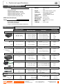
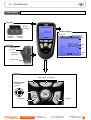
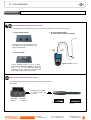
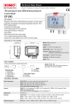
Supplied with Calibration certificate SENTRONIC AG Produkte, Support und Service MP 200 Manometer Rugghölzli 2 CH - 5453 Busslingen Tel. +41 (0)56 222 38 18 Fax +41 (0)56 222 10 12 [email protected] www.sentronic.com SENTRONIC AG Produkte, Support und Service Rugghölzli 2 CH - 5453 Busslingen Tel. +41 (0)56 222 38 18 Fax +41 (0)56 222 10 12 [email protected] www.sentronic.com 3 Table of contents I – Technical specifications.............................................................................................4 Technical features..................................................................................................................................4 Specifications...........................................................................................................................................4 II – Introduction...................................................................................................................5 Description................................................................................................................................................5 Connections..............................................................................................................................................6 III – Browsing........................................................................................................................7 IV –Menus.............................................................................................................................8 Probe menu...............................................................................................................................................8 Functions...................................................................................................................................................8 Pressure...............................................................................................................................................................8 Airflow....................................................................................................................................................................8 Area..................................................................................................................................................................8 Duct type...............................................................................................................................................................8 Sizes........................................................................................................................................................................8 K2 Factor..............................................................................................................................................................9 Units........................................................................................................................................................................9 COmax....................................................................................................................................................................9 Gas...........................................................................................................................................................................9 Air velocity............................................................................................................................................................9 Hold - Min/Max...........................................................................................................................................9 Average...........................................................................................................................................................9 Point / point average.......................................................................................................................................10 Automatic average............................................................................................................................................10 Automatic point / point average................................................................................................................10 Configuration................................................................................................................................................10 Thermocouple type............................................................................................................................................10 Display....................................................................................................................................................................10 Units........................................................................................................................................................................10 Integration............................................................................................................................................................10 Compensation.....................................................................................................................................................10 Pressure system................................................................................................................................................10 Solenoid valve......................................................................................................................................................10 Recording.......................................................................................................................................................11 Parameters...................................................................................................................................................12 Language...............................................................................................................................................................12 Date / Time..........................................................................................................................................................12 Beep........................................................................................................................................................................12 Extinction..............................................................................................................................................................12 RF logging.............................................................................................................................................................13 Contrast................................................................................................................................................................13 Backlit.....................................................................................................................................................................13 Key locking............................................................................................................................................................13 Code........................................................................................................................................................................13 Downloading data...................................................................................................................................12 V – General information...................................................................................................13 Info menu...................................................................................................................................................13 Maintenance.............................................................................................................................................14 Warranty...................................................................................................................................................14 SENTRONIC AG Produkte, Support und Service Rugghölzli 2 CH - 5453 Busslingen Tel. +41 (0)56 222 38 18 Fax +41 (0)56 222 10 12 [email protected] www.sentronic.com � ������������������������ ����������������� ��������������� ��������������������������������������� ���� �������������������� 34�������-�������5���6�..����7�(�.��"�� 34�������-�������5���6(��..����7��..��"�� 34�������-�������5���6�.�...����7���(..��"�� 34�������-�������5���6�..������7�(�"�� 34�������-�������5���6(�...������7�&�"�� ����������������������������������������������������������� ������������������������������ !����������"����� #�������$%��$�&�'(&��) ����������������������������!���"������������*�+,& �������������������������$�-����� �� ����������������������.����/�.01 �������������������������(.����/2.01 ������������������������-���"��������.�����(.���! ���������������������������'�. ����������������������%��!����! ���� �!""������#����$������%& '������ 8���������������(29�(2���9��� :�����.�9��������"�-��"������� :�����������&�����-����!���#�!�-��! ������-���!��-���) ����������� ������������� �������������� )��������� �##���#�( �)+��*)+ 6��..����7�6.�(? ���������! �6.�2��� "�� �!��6.�(? ���������! �6������ %����.����6�..��� ������; ( 3���!�<8�� �"�����������; � �:����������"������� .�������������..����/��..�������� �����"���!� %����.����6(��..��� 6.�(?���������! �6(�� ��� %����.����6�.�...��� %����.����6�..��"�� %����.����6(�...��"�� 6.�(?���������! �6�.�� ��� 6.�(?���������! �6.���"�� 6.�(?���������! �6(�"�� .���"�� ��"�� %����(�������=� 6.�'��=�� .����=� %������������..��=� 6.��?���������! �6.�(�=� .����=� � ' =��������=���� ' =� %����.����@@�@@@�'=� 6.�(?���������! �6�?��� ���'=� �=��������>�=������ %���������(.��=� 6.�'��=� .����=� %����(������..��=� 6�?���������! �6.���=� .����=� %����.����@@�@@@�'=� 6.�(?���������! �6�?��� ���'=� �1-�-�-*2+ ����4������ ������5 �=��������>�=������ '+21 ��2��'+� ����4������ ������5 � ' =��������=���� ' =� �*))+,-�.�/��-�0+ *���� .�..��* %����.�����=(.���� 6(�* 6�.�* 6.�.��� >�7 %�����(..������'..01 C�7 %������..����A�.01 6���01����6.��?�,����! �4��-�BB 6.�201����6.��?�,����! �4��-�BB .���01 D�7 %�����(..�����..01 6.��01����6.��?�,����! �4��-�BB .���01 6.�'?���������! �6.�(�01 6'���� 6���?���������! � .���01 %����.����(���* %����.�����.�* .�.��* .�.���� -�+) ���*��+��$������������������& 01��0% � .���01 ���.�-��������� D���� 13 01��0% ��� %�����(.����/2.01� %����.����(..���� %����(..�����..���� .������ 0������3 ��� ?+�+ ?*3+ %����.�����.�...����� #8�+�7�.��2..) %����.����(.?+�+ ����� 6(.?�����-�����������(.�01���� &��?;,�6���?;, .�.��?+�+ .�..��?*3+ %����.�����?*3+ B�����-�������!��������!��������-��!��5������������!���"���������!�����!���!���!�"�� -���!�������������-����!�����������-���!�����������!�����!��������������-��5������E-���������!�����!� BB�D����-��������9���������������"�������4�����!��!�01�����"��������!�� ���������4��-���!��!����3!�������"� ���4��-������!�������� SENTRONIC AG Produkte, Support und Service Rugghölzli 2 CH - 5453 Busslingen Tel. +41 (0)56 222 38 18 Fax +41 (0)56 222 10 12 [email protected] www.sentronic.com II – Introduction 5 Description Top view Module connection Graphic display Battery level mini-Din C2 connector Memory status used mini-Din C1 connector Hour Value Side view Unit Power supply connection Circular menu USB port for KIMO cable Elastomer grip Keypad Access keys for circular menu Browsing joystick : ● 4 directions ● Validation Escape key SENTRONIC AG Produkte, Support und Service On/Off key Rugghölzli 2 CH - 5453 Busslingen Tel. +41 (0)56 222 38 18 Fax +41 (0)56 222 10 12 [email protected] www.sentronic.com II – Introduction 6 Connections Interchangeable measurement module Interchangeable modules with Smart-plus system are automatically recognized when connected to the instrument. 1. Current / Voltage module 3. Air velocity with Pitot tube : Pressure module + Pitot tupe (optionnal) It allows current or voltage measurements on V/ A1 or VA/2 channels with current/voltage input cables or ammeter clamps. (+) Static pressure PS 2. Pressure module (-) Static pressure PT Dynamic pressure = PT - PS It allows differential pressure, air velocity or airflow measurements with Pitot tube or Debimo on two pressure inputs (- and +) and thermocouple temperature measurement on Tc1 channel with wire thermocouple probes equipped with a miniature male connector. Wire probes with Smart-plus system Wire probes with Smart-plus system are automatically recognized when connected to the instrument. CO/temp probe is connected on min-DIN connectors C1 and / or C2 mini-Din C2 connector SENTRONIC AG mini-Din C1 connector Produkte, Support und Service Rugghölzli 2 CH - 5453 Busslingen Secured Mini-Din Connector Retractable cable lg. 450 mm, up to 2.4 m. Tel. +41 (0)56 222 38 18 Fax +41 (0)56 222 10 12 [email protected] www.sentronic.com 7 III – Browsing Power-up Enter key code with directional pad. (if the locking is activated) and e Homepage display Probe Infos Select a sub menu with access keys Params or with arrow keys Probe connection Probe display Select a connection with right and left keys Connections can be activated or deactivated with or Return to previous screen Infos Measure Params Select a sub function with access keys or with arrow keys Measurement PRESSURE Display AIRFLOW display AIR VELOCITY display Select a sub function with access keys or with arrow keys Rec. Alarms Probe Hold Params Airflow Config Veloci. AutoZ Avg. Rec. Alarms Probe Params Config Hold Veloci. Press AutoZ Rec. Avg. Area Alarms Probe Hold Params Airflow Config Press AutoZ Avg. Communication interrupted Check probes connection SENTRONIC AG Produkte, Support und Service Rugghölzli 2 CH - 5453 Busslingen Tel. +41 (0)56 222 38 18 Fax +41 (0)56 222 10 12 [email protected] www.sentronic.com 8 IV – Menus Probe menu Wire probes and modules with Smart-plus system are automatically recognized from first connection. The ''Probe'' menu only appears when probes or module are connected. This menu allows to view probe information plugged to C2, Module, C1 or wireless connections. (See « Connections » p 6 for more information about connections). Probe display Available information are : • Sensor type, Serial number, Date of last calibration or adjustement, Probes Status (enabled ou disabled). On enabled mode, the probe is connected, the measurement is carried out and the value is displayed. On disabled mode, the probe is connected, the measurement is not carried out and the value is not displayed. Measure Infos Params Functions Pressure PRESSURE display Access Pressure function by means of Pressure key. With Pressure function, you can access to following sub-functions - Hold - see Air velocity - Config. (Configuration) - see Air velocity - Params (Parameters) - see Air velocity - Avg. (Average) - see Air velocity - Rec (Recording) - see Air velocity Rec. Alarms AutoZ Probe Config Hold Params Airflow AutoZ Veloci. Avg. This sub-function allows to compensate for any long-term drifts of the sensing element by a manual adjustment of the zero. For the ±500 Pa measurement module, self-calibration is performed by the solenoid valve. Once pressing Autoz key, the zero is readjusted. This function can also be automatically performed by using the solenoid valve function. For others measurement modules, self-calibration is performed by disconnecting the two pressure inlets of the sensor, then by pressing Autoz key. AIRFLOW Access Airflow function by means of Airflow key. With Airflow function, you can access to following sub-functions - Hold – see Air velocity - Area - Config. (Configuration) - see Air velocity - Params (Parameters) - see Air velocity AIRFLOW display - Avg. (Average) - see Air velocity - Rec (Recording) - see Air velocity Area • Duct type To select vent Type press OK or . Select Lx W or Diam or K factor with arrow buttons and . Confirm with OK. If K factor is selected, you must enter value. You can choose a K factor already registered by selecting with and . Confirm with OK. This factor can be modified by selecting with and , then confirm with OK or . Select Modify with OK or . Enter factor by means of arrow keys and . Confirm with OK or . Rec. Probe Hold Alarms Params Veloci. Config Press AutoZ Area • Sizes Press or OK to enter into sizes sub function. You can choose an air vent already registered by selecting it with arrow keys and . Confirm with OK or . This air vent can be modified by selecting it with arrows keys and , then Confirm with OK or . Select Modify with OK or . Enter sizes by means of arrow keys and . Confirm with OK or . SENTRONIC AG Produkte, Support und Service Rugghölzli 2 CH - 5453 Busslingen Tel. +41 (0)56 222 38 18 Fax +41 (0)56 222 10 12 [email protected] www.sentronic.com Avg. 9 IV – Menus • K2 factor Press or OK to enter into the K2 factor sub function. Select respectively ON or OFF with and in order to enable or disable this function. Confirm with OK . • Units To select the unit press OK or . Select mm or in with arrow buttons and . Confirm with OK. COmax The CO mode is available when a CO/Temperature probe is connected. You can access this function selecting COmax with the access key CO max The CO is measured on an adjustable period, the maximum value measured in this period is called CO max . When CO peak is selected, the period is diplayed (30 seconds by default). Press Valid. to launch the measurement. When the countdown is finished, the CO max is displayed. To modify the period, press Period with the access key. Modify time with arrows keys and . Confirm with OK or . Gas Connect the gas leak detection probe to the the AMI310 then turn on the AMI310. Press Measure button. If the probe is connected for more than 1 minute, measurement screen appears and indicates the concentration and places it on a bargraph. If the probe has been just connected, the screen indicates the remaining time of warm up then the measurement screen appears, indicates the concentration and places it on a bargraph. Several actions are possible during the measurement : ● Press Hold to fix the measurement. When the measurement is fixed, press Min Max to access to maximum and minimum values of the measurement. From this screen, press Measure to back to measurement. ● Press Alarms to modify alarm threshold. Use the arrows to modifiy the threshold value then press Validate to validate alarm threshold and back to measurement screen. Alarm threshold corresponds to the right value on the bargraph. The beep repetition frequency will increase accordong to the increase of detected gas concentration, and the display will blink at the same frequency. ● During the measurement, follow the path of the gas pipe to controle placing the probe on the pipe. ● GAS DISPLAY ● Alarm threshold Air velocity Access Air velocity function by means of - Hold - Config. (Configuration) - Params (Parameters) - Avg. (Average) - Rec (Recording) Veloci. key. With Air velocity function, you can access to following sub-functions AIR VELOCITY Display Hold - Min./Max. Press 1x in order to select HOLD function : measurement holding on display. Press 2x in order to select Min-Max function : display of minimum and maximum values. Press 3x : back to the continuous measurement. Rec. Alarms Probe Hold Params Airflow Config Press AutoZ Avg. Average Press or OK to enter Average sub function. With and , you can select : point/point average, auto, point/point automatic. Confirm with OK or . SENTRONIC AG Produkte, Support und Service Rugghölzli 2 CH - 5453 Busslingen Tel. +41 (0)56 222 38 18 Fax +41 (0)56 222 10 12 [email protected] www.sentronic.com IV – Menus 10 • Point / point average This function allows to calculate the average value of various points that you can select. Numbers of selected points and parameter for which calculation is carried out, are displayed For adding a new measuring point to this calculation, press OK to confirm. If you click on average icon, max. and min. values, standard deviation, average of each channel and e numbers of measuring points will be displayed. If you want to see all values, select Visu. and scroll with and . • Automatic average This function allows to calculate an average value that the device measured in an interval chosen time. Timer is displayed. Select Start with access key for launching measurement. If you click on average icon, max. and min. values, standard deviation, average of each channel and time chosen will be displayed. • Automatic point/point average This function allows to calculate the average value of various points, calculated themselves on a duration beforehand defined. You must enter duration : click on the Period icon. Select minutes or seconds with arrow buttons and . Scroll digits with and . Confirm with OK. The numbers of points is displayed. Press Ok for launching measurement. If you click on average icon, max. and min. values, standard deviation, average of each channel and numbers of measuring points will be displayed. You can view each measuring points if you click on Visu. Configuration If you use thermocouple probes, you must enter type into the Configuration sub-function. Configuration sub-function allows to: • Select thermocouple type Click on OK or to enter into sub function : a list of thermocouple available ( K, J or T type) appears . Select type with and . Confirm with OK. • Select display Use the arrow key or click on OK to enter into sub function. Select channel using and then confirm with OK. Use or to select ON (displayed) or OFF (not displayed) then confirm with OK. • Select units Click on OK or to enter into sub function : a list of units available appears. Select unit required with and . Confirm with OK. Click on Esc to return to previous screen. • Select integration The coefficient of integration allows to smooth the measure, to avoid variations. Click on OK or to enter into sub function : a list of coefficient (From 0 to 9) appears. Select coefficient required with and . Confirm with OK. Coefficient 0: no integration, important fluctuation in the shown measure. Select compensation It is possible to modify the value of the compensation in temperature. Indeed, the velocity and the airflow with Pitot's tube and with Debimo blades are calculated from a temperature of use in +20°C. It is thus necessary to enter the real temperature of use to obtain more precise results. Click on OK or to enter into the sub function. Select + or – signs with and with and then pass on the first digit with . Enter the first digit then move to the next one with . Confirm with OK. • Select pressure system (only available for Air velocity and Airflow functions) Click on OK or to enter into sub function : a list of pressure systems available appears (Pitot tube L, S, Debimo or Other). Select your system with and . Confirm with OK. If Other is selected, you must enter a value. Click on OK or to enter into sub function. With and , enter the first digit then move to the next one with . Confirm with OK. • Solenoid valve (available with the ± 500 Pa module) Click on OK or to enter into the sub function. Select respectively ON or OFF with and in order to enable or disable the solenoid valve function. Confirm wih OK or . When the solenoid valve is enabled, it runs every minute. SENTRONIC AG Produkte, Support und Service Rugghölzli 2 CH - 5453 Busslingen Tel. +41 (0)56 222 38 18 Fax +41 (0)56 222 10 12 [email protected] www.sentronic.com 11 IV – Menus Recording The Recording menu allows a measurement dataset. You can choose between a planned or a continuous dataset. Memory capacity of the instrument is up to 8,000 points or 50 datasets. 1. Create or launch a continuous dataset Select dataset A continuous dataset can be carried out using MP200 and is composed of several dated measuring points. The operator can choose an automatic or a manual dataset, with an instant value or an average. This datasets can't be set using Datalogger-10 Software. 1.1 Manual dataset Select name A manual dataset is composed of measuring points selected by the operator. a. Click on OK or to enter into sub function. b. Select Manual with and . Confirm wih OK. c. Select Name with and . Confirm wih OK or . Enter dataset name with arrow keys and e. Confirm wih OK. d. For measurement launching, click on OK with the access key. The number of points selected and the parameter are displayed. e. To save your dataset click on Save with the access key. Manual dataset 1.2 Automatic dataset An automatic dataset is composed of measuring points with interval of time. a. Click on OK or to enter sub function. b. Select Auto. with and . Confirm wih OK. c. Select Name with and . Confirm wih OK or . Enter dataset name with the arrow keys and e. Confirm wih OK. d. Enter dataset time and interval of time between 2 measurements by selecting Period with access key. Select Duration or Interval with and . Confirm wih OK. Enter minutes and seconds with arrow keys and ( from 1 minutes to 24 hours for the duration and from 5 seconds to 10 minutes for the interval). Confirm with OK. e. Select Start for dataset launching. Automatic dataset 2. Launch a planned dataset A planned dataset is composed of several locations. For each location, the operator can enter a theorical value and a tolerance for the parameter to be controlled. Planification must be made via the software. a. Click on OK or to enter into sub function. b. Select Planned with and . Confirm wih OK. c. Choose dataset name with and . Confirm wih OK. d. Select the location with and . Confirm wih OK. SENTRONIC AG Produkte, Support und Service Rugghölzli 2 CH - 5453 Busslingen Tel. +41 (0)56 222 38 18 Fax +41 (0)56 222 10 12 [email protected] www.sentronic.com 12 IV – Menus 3. Preview of tables of points of datasets Dataset summary You can display tables of points of datasets performed on the device. a. Go to Recording menu. b. Select Display. Click on OK to validate. c. Select dataset name with arrow keys et . Click on OK to validate. Summary screen of selected dataset is displayed. From this screen, you can : ● Select other dataset using arrow keys t and u. ● Display data of other channels using arrow keys p and q. Dataset table d. Click on Mesure to display values table of selected dataset. From this screen you can : ● Browse values table of points of the same channel pressing Prev. or Next. ● Change of channel with arrow keys and . ● Back to dataset summary screen pressing Visu. 4. Delete all datasets Select Delete with and . Confirm wih OK. Parameters • Language Click on OK or to enter and a list of languages available appears. Select language with arrow keys and and Confirm wih OK. • Date / time Click on OK or to enter into sub function. Enter the day with and then move to the next digit with . Repeat this operation for the month, year, hour and minute. Confirm wih OK. • Beep This sub-function allows to enable or disable the keypad beep. Click on OK or to enter into the sub function. Select respectively ON or OFF with and in order to enable or disable the beep. Confirm wih OK. • Extinction This sub-function allows to enable the automatic shut-off and to select the delay in minute. Click on OK or to enter into the sub function. Select, with and , OFF in order to disable the automatic shut-off or enter the delay (from 15 to 120 minutes). Confirm wih OK. SENTRONIC AG Produkte, Support und Service Rugghölzli 2 CH - 5453 Busslingen Tel. +41 (0)56 222 38 18 Fax +41 (0)56 222 10 12 [email protected] www.sentronic.com 13 IV – Menus • RF logging This sub-function allows to enable or disable the RF Logging. Click on OK or to enter into the sub function. Select respectively ON or OFF with and in order to enable or disable this function. Confirm wih OK. • Contrast This sub-function allows to modify the contast. Click on OK or to enter. Select your contrast level (from 0 to 9 or AUTO) with and . Confirm wih OK. • Backlit This sub-function allows to modify the backlit. Click on OK or to enter. Select your backlit level (from 0 to 9 or AUTO) with and . Confirm wih OK. If you select AUTO, the MP200 adjuts automatically the backlit according to the room brightness. • Key locking This sub-function allows to enable or disable the key lock. Click on OK or to enter into sub function. Select respectively ON or OFF with and in order to enable or disable this function. Confirm wih OK. If the locking is enabled, the code menu appears • Code This sub-function allows to enter the security code. Click on OK or and the code appears. Enter the first digit of the code with and then move to the next one with . Confirm wih OK. Downloading data see DataLogger-10 user manual chapter III – Read device page 6. V – General informations Info menu This menu allows to view the serial number of instrument and firmware version. Battery When battery indicator flashes it is recommended to change the batteries: 1. Remove the front part at the back of the instrument. 2. Remove batteries 3. Insert new batteries (AA-LR6 1,5V) in accordance with proprer polarity drew inside the housing. 4. Replace the front. SENTRONIC AG Produkte, Support und Service Rugghölzli 2 CH - 5453 Busslingen Tel. +41 (0)56 222 38 18 Fax +41 (0)56 222 10 12 [email protected] www.sentronic.com 14 V – General informations Maintenance KIMO performs calibration, adjustment and maintenance of all your instruments to guarantee a constant level of quality of your measurements. In regards of Quality insurance norms, we recommend that the instruments are checked once a year. Warranty KIMO Instruments have 1-year guarantee for any manufacturing defect (return to our After-Sales Service required for appraisal). SENTRONIC AG Produkte, Support und Service Rugghölzli 2 CH - 5453 Busslingen Tel. +41 (0)56 222 38 18 Fax +41 (0)56 222 10 12 [email protected] www.sentronic.com