1
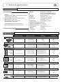
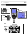
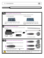
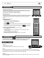
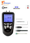
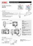
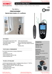
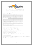
Supplied with Calibration certificate Multi-Functional Anemometer VT 200 Table of contents 3 I – Technical specifications.............................................................................................4 Technical features..................................................................................................................................4 Specifications...........................................................................................................................................4 II – Introduction...................................................................................................................5 Description................................................................................................................................................5 Connections..............................................................................................................................................6 III – Browsing........................................................................................................................7 IV – Menus............................................................................................................................8 Probe menu...............................................................................................................................................8 Using wire probes and modules............................................................................................................8 Using wireless probes...............................................................................................................................8 Airflow menu............................................................................................................................................8 Area..................................................................................................................................................................8 Duct type...............................................................................................................................................................8 Sizes........................................................................................................................................................................8 K2 factor...............................................................................................................................................................8 Units........................................................................................................................................................................9 Using Hotwire..........................................................................................................................................9 Air velocity menu.....................................................................................................................................9 Hold - Min/Max...........................................................................................................................................9 Average...........................................................................................................................................................9 Point / point average.......................................................................................................................................9 Automatic average............................................................................................................................................9 Automatic point/point average...................................................................................................................9 Configuration................................................................................................................................................10 Thermocouple type............................................................................................................................................10 Display....................................................................................................................................................................10 Units........................................................................................................................................................................10 Recording.......................................................................................................................................................10 Parameters...................................................................................................................................................12 Language...............................................................................................................................................................12 Date / hour..........................................................................................................................................................12 Beep........................................................................................................................................................................12 Extinction..............................................................................................................................................................12 Contrast................................................................................................................................................................12 Backlit.....................................................................................................................................................................12 Key locking............................................................................................................................................................12 Code........................................................................................................................................................................12 Downloading data...................................................................................................................................12 V – General Information...................................................................................................13 Info menu...................................................................................................................................................13 Maintenance.............................................................................................................................................13 Warranty...................................................................................................................................................13 4 I – Technical specifications Technical features Sensing elements Hot wire : Air velocity : thermistance with a negative temperature coefficient. Ambient temperature : Pt100 1/3 Din. Ø 70 and 100 mm vane probe : Hall effect sensor Ambient temperature : Pt100 class A. Ø 14 mm vane probe : Proximity sensor Ambient temperature : Pt100 class A. Thermocouple prones : K, J and T type class 1 Smart-plus Pt100 probes : Pt100 class 1/3 Din VT200 connections (See P6) Display...............................Graphic display 128x128 pixels Dim. 50 x 54 mm, blue blacklit, Display of 6 measurements (including 4 simultaneously) Housing.............................IP54, ABS shock-proof Keypad...............................Metal-coated, 5 keys, 1 joystick Conformity........................Electromagnetical compatibility (NF EN 61326-1 norm) Power supply....................4 alcaline batteries 1,5V LR6 Operating environment...Neutral gas Operating temperature..from 0 to 50°C Storage temperature.....from -20 to +80°C Auto shut-off....................adjustable from 0 to 120 min Weight...............................12 oz (380g) Languages........................English, French Specifications Measuring units Measuring range V, mA From 0 to 2.5 V Accuracy* Resolutions CURRENT/VOLTAGE From 0 to 10 V From 0 to 4/20 mA ±2mV ±10mV ±0.01mA 0.001 V 0.01 V 0.01 mA THERMOCOUPLE (See related datasheet) °C, °F + K : From -200 to 1,300°C J : From -100 to 750°C ±1.1°C or ±0.4% Reading value** ±0.8°C or ±0.4% Reading value** 0.1 °C T : From -200 to 400°C ±0.5°C or ±0.4% Reading value** 0.1 °C ±3% of reading ±0.03 m/s ±3% of reading ±0.1 m/s 0.01 m/s From 3.1 to 30 m/s From -20 to +80°C From 0 to 99,999 m 3 /h ±0.3% of reading ±0,25°C ±3% of reading ±0.03*area (cm2) From 0.25 to 3 m/s From 3.1 to 35 m/s ±3% of reading ±0.1m/s ±1% of reading ±0.3m/s From -20 to +80°C From 0 to 99,999 m 3 /h ±0.4% of reading ±0.3°C ±3% of reading ±0.03*area (cm2) From 0.3 to 3 m/s From 3.1 to 35 m/s From -20 to +80°C ±3% of reading ±0.1m/s ±1% of reading ±0.3m/s ±0.4% of reading ±0.3°C ±3% of reading ±0.03*area (cm2) 0.1 °C HOTWIRE- Standard and telescopic Air velocity Temperature AirFlow m/s, fpm, Km/h °C, °F m 3 /h, cfm, l/s, m 3 /s From 0.15 to 3 m/s 0.1 m/s 0.1 °C 1 m3/h Ø 100 mm VANE PROBE Air velocity Temperature Airflow m/s, fpm, Km/h °C, °F m 3 /h, cfm, l/s, m 3 /s 0.01 m/s 0.1 m/s 0.1 °C 1 m3/h Ø 70 mm VANE PROBE Air velocity Temperature Airflow m/s, fpm, Km/h °C, °F m 3 /h, cfm, l/s, m 3 /s From 0 to 99,999 m 3 /h 0.1 m/s 0.1 °C 1 m3/h Ø 14 mm VANE PROBE Air velocity Temperature Airflow m/s, fpm, Km/h °C, °F m 3 /h, cfm, l/s, m 3 /s From 0.8 to 3 m/s From 3.1 to 25 m/s From -20 to +80°C From 0 to 99,999 m 3 /h ±3% of reading ±0.1m/s ±1% of reading ±0.3m/s ±0.4% of reading ±0.3°C ±3% of reading ±0.03*area (cm2) 0.1 m/s 0.1 °C 1 m3/h Wire or wireless Pt100 probes (See related datasheet) °C, °F From -50 to +250°C (according to reference) ±0.3% of reading ±0.25°C (according to reference) *All accuracies indicated in this document were stated in laboratory conditions and can be guaranteed for measurements carried out in the same conditions, or carried out with required compensation. **The accuracy is expressed either by a deviation in °C, or by a percentage of the value concerned. Only the bigger value is considered. 0.01 °C II – Introduction 5 Description Top view Module connections Graphic display Battery level mini-Din C2 connector Memory status used mini-Din C1 connector Hour Value Side view Power suply connection Unit Circular menu USB port for KIMO Cable Elastomer protection Keypad Access keys for circular menu Browsing joystick : ● 4 directions ● Validation Escape key On/Off key II – Introduction 6 Connections Interchangeable measurement modules Interchangeable modules with Smart-plus system are automatically recognized when connected to the instrument. 1. Current / voltage module 2. Thermocouple module It allows current or voltage measurements on V/A1 or VA/2 channels with current/voltage input cables or ammeter clamps. It allows thermocouple temperature measurement on Tc1, Tc2, Tc3 and Tc4 channels with type K, J or T with wire thermocouple probes equiped with a miniature male connector. Wire probes with Smart-plus system Wire probes with Smart-plus system are automatically recognized when connected to the instrument. Probes are connected on min-DIN connectors C1 and / or C2 mini-Din C2 connector mini-Din C1 connector Secured Mini-Din Connector Non-exhaustive list of probes Wireless probe/instrument communication Wireless communication between probe and instrument with automatic recognition after power-up. Vane probes and PT100 probes are displayed on Vit, Tr1 or Tr2 channels followed by wireless communication Reco Wireless probes shall be located near the instrument for initial recognition. Connection between VT200 and wireless probes must be established. See submenu ''Wireless probes'' p 8. 7 III – Browsing Power-up Enter key code with directional pad. (if the locking is activated) and e Homepage display Select a sub menu with access keys Probes Infos Params or with arrow keys Probe connection Probe display Select a connection with right and left keys Connections can be activated or deactivated with or Measure Infos Params Select a sub menu with access keys Measurement Airflow measurement display Air velocity measurement display Return to previous screen Select sub menu with arrows keys or access keys Probe Alarms Rec. Hold Params Area Veloci. Avg. Config Probe Hold Rec. Alarms Avg. Config Params Communication interrupted Check probes connection Airflow 8 IV – Menus Probe menu 1. Using wire probes and modules Wire probes and modules with Smart-plus system are automatically recognized from first connection. The ''Probe'' menu only appears when probes or module are connected. This menu allows to view probe information plugged to C2, Module, C1 or wireless connections. (See « Connections » p 6 for more information about connections). Available information are : • Sensor type, Serial number, Date of last calibration or adjustement, Probes Status (enabled ou disabled). On enabled mode, the probe is connected, the measurement is carried out and the value is displayed. On disabled mode, the probe is connected, the measurement is not carried out and the value is not displayed. Probes display Measure Infos Params RF probes display 2. Using wireless communication A- Add a wireless probe A1. Go to probe menu by pressing ''Probe'' access key. A2. With arrow keys and , go to ''RF probes'' display. A3. Select New with access key. A4. Power up the probe and press multifunction button until LED blinks. Once the probe is recognized, information appears. Left button allows to return to the wireless probes display and to access all wireless probes already recognized by the instrument. With access keys, it is possible to delete Del a wireless probe. RF probes searching B- Select a wireless probe already created. B1. Power up the wireless probe (short press on Multifunction button). B2. Go to ''Probe'' menu. B3. With arrows keys and , go to ''RF probes'' display. All the wireless probes already recognized appear. B4. Select the suitable wireless probe with or . B5. Go to probe informations using arrow key . B6. Enable the wireless probe with arrows keys and and confirm with OK . RF probes detected RF probes display Sondes RF AIRFLOW menu Access Airflow function by means of Air flow key. With Airflow function, you can access to following sub-functions Hold, Area, Configuration, Parameters, Average, Alarms et Recording. For using subfunctions Hold, Average, Alarms, Recording and Configuration see chapter Air velocity menu. AIRFLOW Display Area • Duct type To select vent Type press OK or . Select Lx W or Diam or K 25 with arrow buttons and . Confirm with OK. Probe Alarms Rec. Hold Params Area Veloci. Avg. Config • Sizes Press or OK to enter into sizes sub function. You can choose an air vent already registered by selecting it with arrow keys and . Confirm with OK or . This air vent can be modified by selecting it with arrows keys and , then Confirm with OK or . Select Modify with OK or . Enter sizes by means of arrow keys and . Confirm with OK or . • K2 factor Press or OK to enter into the K2 factor sub function. Select respectively ON or OFF with and in order to enable or disable this function. Confirm with OK . 9 IV – Menus • Units To select the unit press OK or . Select mm or in with arrow buttons and . Confirm with OK. Using a hotwire Sensing element (air velocity) Sensing element (temperature) 1. Connect the hotwire probe to VT 200. Probe menu appears. 2. Slide down protection tube (1). 3.The probe must be perpendicular to airflow : the red point at the bottom of the probe must face airflow. 4. Press OK to enter in the Measurement menu, the air velocity and temperature values are displayed. 5. With arrow keys and go to « Config » and press OK. 6. Go to « Air pressure » then press OK. 7. Enter air pressure. 8. Press« Valid. » then « Esc » to go back to measurement mode. Air flow direction Protection tube (1) Red point AIR VELOCITY menu Access Airflow function by means of Veloci. key. With Velocity function, you can access to following sub-functions Hold, Area, Configuration, Parameters, Average, Alarms et Recording. AIR VELOCITY display Hold - Min./Max. Press 1x in order to select HOLD function : measurement holding on display. Press 2x in order to select Min-Max function : display of minimum and maximum values. Press 3x : back to the continuous measurement. Average • PointMoyenne / point average Probe Hold Rec. Alarms Avg. Params Config Airflow This function allows to calculate the average value of various points that you can select. Numbers of selected points and parameter for which calculation is carried out, are displayed For adding a new measuring point to this calculation, press OK to confirm. If you click on average icon, max. and min. values, standard deviation, average of each parameter and numbers of measuring points will be displayed. If you want to see all values, select Visu. and scroll with and . • Automatic average This function allows to calculate an average value that the device measured in an interval chosen time. Timer is displayed. Select Start with access key for launching measurement. If you click on average icon, max. and min. values, standard deviation, average of each channel and time chosen will be displayed. • Automatic point/point average This function allows to calculate the average value of various points, calculated themselves on a duration beforehand defined. You must enter duration : click on the Period icon. Select minutes or seconds with arrow buttons and . Scroll digits with and . Confirm with OK. The numbers of points is displayed. Press Ok for launching measurement. If you click on average icon, max. and min. values, standard deviation, average of each channel and numbers of measuring points will be displayed. You can view each measuring points if you click on Visu. 10 IV – Menus Configuration Configuration sub-function allows to: : If you use thermocouple probes, you must enter type into the Configuration sub-function. • Select thermocouple Click on OK or to enter into sub function : a list of thermocouple available ( K, J or T type) appears . Select type with and . Confirm with OK. • Select display Click on OK or to enter into sub function. Select channel required with arrow keys and and confirm with OK. With and . Select respectively ON or OFF with and in order to enable or disable this function. Confirm with OK . • Select units Click on OK or to enter into sub function : a list of units available appears. For each channel, select unit required with and . Confirm with OK. Click on Esc to return to previous screen. Recording The Recording menu allows a measurement dataset. You can choose between a planned or a continuous dataset. Memory capacity of the instrument is up to 8,000 points or 50 datasets. 1. Create or launch a continuous dataset A continuous dataset can be carried out using VT200 and is composed of several dated measuring points. The operator can choose an automatic or a manual dataset, with an instant value or an average. This datasets can't be set using Datalogger-10 Software. Select dataset 1.1 Manual dataset A manual dataset is composed of measuring points selected by the operator. a. Click on OK or to enter into sub function. b. Select Manual with and . Confirm wih OK. c. Select Name with and . Confirm wih OK or . Enter dataset name with arrow keys and e. Confirm wih OK. d. For measurement launching, click on OK with the access key. The number of points selected and the parameter are displayed. e. To save your dataset click on Save with the access key. Enter name Manual dataset 1.2 Automatic dataset An automatic dataset is composed of measuring points with interval of time. a. Click on OK or to enter sub function. b. Select Auto. with and . Confirm wih OK. c. Select Name with and . Confirm wih OK or . Enter dataset name with the arrow keys and e. Confirm wih OK. d. Enter dataset time and interval of time between 2 measurements by selecting Period with access key. Select Duration or Interval with and . Confirm wih OK. Enter minutes and seconds with arrow keys and ( from 1 minute to 24 hours for the duration and from 5 seconds to 10 minutes for the interval). Confirm with OK. e. Select Start for dataset launching. Automatic dataset 11 IV – Menus 2. Launch a planned dataset A planned dataset is composed of several locations. For each location, the operator can enter a theorical value and a tolerance for the parameter to be controlled. Planification must be made via the software. a. Click on OK or to enter into sub function. b. Select Planned with and . Confirm wih OK. c. Choose dataset name with and . Confirm wih OK. d. Select the location with and . Confirm wih OK. 3. Preview of tables of points of datasets You can display tables of points of datasets performed on the device. Dataset summary a. Go to Recording menu. b. Select Display. Click on OK to validate. c. Select dataset name with arrow keys et . Click on OK to validate. Summary screen of selected dataset is displayed. From this screen, you can : ● Select other dataset using arrow keys t and u. ● Display data of other channels using arrow keys p and q. d. Click on Mesure to display values table of selected dataset. From this screen you can : ● Browse values table of points of the same channel pressing Prev. or Next. ● Change of channel with arrow keys and . ● Back to dataset summary screen pressing Visu. 4. Delete all datasets Select Delete with and . Confirm wih OK. Dataset table IV – Menus 12 Parameters • Language Click on OK or to enter and a list of languages available appears. Select language with arrow keys and and Confirm wih OK. • Date / Time Click on OK or to enter into sub function. Enter the day with and then move to the next digit with . Repeat this operation for the month, year, hour and minute. Confirm wih OK. • Beep This sub-function allows to enable or disable the keypad beep. Click on OK or to enter into the sub function. Select respectively ON or OFF with and in order to enable or disable the beep. Confirm wih OK. • Extinction This sub-function allows to enable the automatic shut-off and to select the delay in minute. Click on OK or to enter into the sub function. Select, with and , OFF in order to disable the automatic shut-off or enter the delay (from 15 to 120 minutes). Confirm wih OK. • RF logging This sub-function allows to enable or disable the RF Logging. Click on OK or to enter into the sub function. Select respectively ON or OFF with and in order to enable or disable this function. Confirm wih OK. • Contrast This sub-function allows to modify the contrast. Click on OK or to enter. Select your contrast level (from 0 to 9) with and . Confirm wih OK. • Backlit This sub-function allows to modify the backlit. Click on OK or to enter. Select your backlit level (from 0 to 9 or AUTO) with and . Confirm wih OK. If you select AUTO, the VT200 adjuts automatically the backlit according to the room brightness. • Key locking This sub-function allows to enable or disable the key lock. Click on OK or to enter into sub function. Select respectively ON or OFF with and in order to enable or disable this function. Confirm wih OK. If the locking is enabled, the code menu appears • Code This sub-function allows to enter the security code. Click on OK or and the code appears. Enter the first digit of the code with and then move to the next one with . Confirm wih OK. Downloading data See DataLogger-10 user manual chapter III – Read device page 6. 13 V – General information Info menu This menu allows to view the serial number of instrument and firmware version. Battery When battery indicator flashes it is recommended to change the batteries: 1. Remove the front part at the back of the instrument. 2. Remove batteries 3. Insert new batteries (AA-LR6 1,5V) in accordance with proprer polarity drew inside the housing. 4. Replace the front. Maintenance E Instruments International performs calibration, adjustment and maintenance of all your instruments to guarantee a constant level of quality of your measurements. In regards of Quality insurance norms, we recommend that the instruments are checked once a year. Warranty E Instruments have a 1-year guarantee for any manufacturing defect (return to our After-Sales Service Department for appraisal). E Instruments International LLC 172 Middletown Blvd - Suite B201 Langhorne, PA 19047 Tel.: 215 750 1212 Fax: 215 750 1399 E-mail: [email protected] Web: www.E-Inst.com Distributed by: Temperature & Process Instruments, Inc. 1767 Central Park Ave. Suite 112 Yonkers, NY 10703 Phone: 914-673-0333 Web Site: www.tnp-instruments.com