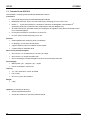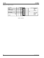
1
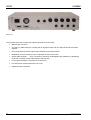
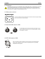
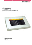
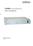
CDS200 II
Central Control Unit DPS202
Operating instructions
Version 3.0
DPS202
CDS200 II
Printed in Germany
If you have questions about this manual please contact:
Brähler ICS Konferenztechnik
International Congress Service AG
P.O. Box 32 64
D-53627 Königswinter
Wahlfelder Mühle 3
D-53639 Königswinter
T +49 (0)2244 930-0
E [email protected]
You will find further information about our products on the internet at:
www.braehler.com
© 2007
BRÄHLER ICS AG, Königswinter
All rights reserved, especially (also partly) the translation, reprint, reproduction through copying or other similar
methods.
BRÄHLER ICS reserves the right to make changes without notice.
INFRACOM® and DIGIMIC® are registered trademarks
Operating instructions CDS200 II, DPS202,
Sep 2009
2
Copyright by Brähler ICS
CDS200 II
DPS202
CAUTION
DANGER OF ELECTRIC SHOCK
DO NOT OPEN DEVICES
Do not open housing with mains cable connected.
Maintenance operations may only be executed by
qualified personnel.
Our equipment and installations have been built and tested according to the latest state of the art. Under
normal conditions, they do not require any special maintenance.
However, please be aware of the following:
; Positioning - secure and stable position of the equipment
; Ventilation - operate equipment with proper ventilation. Avoid heat sources such as heating radiators etc.
; Mains connection – pass all power cables so that they will not be damaged
; Cable connections - avoid trip-traps
; Liquids - avoid penetration of liquids into the housing
; Power sockets - operate equipment only with power sockets that are connected to ground according to
the relevant specifications and regulations
Warning: Never expose equipment to rain or humidity
Rough handling of the equipment, such as strong shocks or vibrations, may result in damages. Inappropriate
handling and storage, which does not conform to the operating instructions, may also lead to equipment
damages
Copyright by Brähler ICS
3
DPS202
4
CDS200 II
Copyright by Brähler ICS
CDS200 II
DPS202
Content
1. About this manual ........................................................................................... 6
Symbols ............................................................................................................. 6
2. Important remarks ........................................................................................... 7
3. Short description Central Control Unit DPS202 ................................................... 9
4. Connectors ................................................................................................... 11
4.1
4.2
4.3
4.4
4.5
4.6
4.7
4.8
Mains power connecter ................................................................................ 11
Audio (AF)-LINK connector (S8G)................................................................... 11
EXT LS-IN connector (XLR) ........................................................................... 11
MIXER/PA line out connector (XLR)................................................................ 12
UNITS 1 … 4 line connector S8G................................................................... 12
PC IN (C15 Input) ........................................................................................ 12
PC LINK (C15 Output) .................................................................................. 12
Connecting to earth ..................................................................................... 13
5. Starting Up ................................................................................................... 14
5.1 Starting Setup ............................................................................................. 14
5.1.1 Status displays ................................................................................................ 14
5.2 STAND ALONE mode ................................................................................... 16
5.2.1 MIC-Modes...................................................................................................... 17
5.2.2 MIC-ROUTING (Microphone-Routing) .................................................................. 18
5.2.3 LS (loudspeaker) – Routing................................................................................ 18
5.2.4 System-Setup .................................................................................................. 19
5.2.4.1 UNIT-NO: AUTOMATIC mode..................................................................... 19
5.2.4.2 UNIT-NO: Semi-AUTOMATIC Mode............................................................. 20
5.2.5 System Setup: Chairman................................................................................... 21
5.3 Test-Routines .............................................................................................. 22
5.3.1 MICROPHONE TEST ......................................................................................... 22
5.3.2 MIC-LEDs ALL ON oder OFF .............................................................................. 23
5.3.3 Information about Firmware Version ................................................................... 23
5.4 PC Remote Mode ......................................................................................... 24
5.4.1 Single Central Control Unit ................................................................................ 24
5.4.2 Multiple Central Control Units ............................................................................ 25
6. Routing diagram ............................................................................................ 26
7. Short Overview ............................................................................................. 27
7.4 Technical Data DPS202 ................................................................................ 28
7.5 Connector pinnings for service information...................................................... 29
8. Applications.................................................................................................. 31
Troubleshooting ................................................................................................ 34
Warranty .......................................................................................................... 35
Service form ..................................................................................................... 37
Contact Information........................................................................................... 39
Copyright by Brähler ICS
5
DPS202
CDS200 II
1. About this manual
Symbols
The following symbols and fonts are used in this manual:
This sign indicates an important note, which has to be followed to guarantee that the functions of the
unit, the security of any data or your health are not put at risk.
Indicates additional information, remarks and tips
Describes activities that must be performed in the shown order
Words in bold letters require your special attention.
6
Copyright by Brähler ICS
CDS200 II
DPS202
2. Important remarks
2.1 For customers in the EU and in the USA
Our equipment has been tested and complies with the requirement of the CE test. This guarantees the
protection against harmful interferences, when the equipment is operating in a commercial environment. If the
unit is not proper installed to this user manual it may causes radio interferences. Any changes or modifications
not explicit approved in this manual could void your authority to operate this equipment.
The equipment must be connected to earth!
2.2 Safety
Check that the operating voltage of the unit is identical with the voltage of your local power supply. If a voltage
conversion is required, consult your BRÄHLER ICS dealer or qualified personnel.
Should any liquid or solid object fall into the housing, unplug the unit and let it check by qualified personnel
before further operation. Unplug the unit from the power outlet or set the main power switch to OFF if it’s not
used for several days. To disconnect the cord, pull it out holding the plug. Never pull the cord itself.
2.3 Installation
Allow proper air circulation to prevent internal heat built-up. Do not place the unit on a surface that may block
the ventilation holes.
Do not install the unit in a location near heat sources or in a place exposed to direct sunlight, excessive dust,
humidity, mechanical vibration or shock.
To avoid condensation do not install the unit where the temperature may increase rapidly.
2.4 Cleaning
To keep the housing in its original condition, periodically clean it with a soft cloth. Stubborn stains may be
removed with a cloth lightly dampened with a mild detergent solution. Never use organic solvents such as
thinners or abrasive cleaners since these will damage the cabinet.
2.5 Repacking
Save the original shipping carton and packing material; they will become useful if you ever have to ship the
unit. In this case please keep the manual together with the unit. For maximum protection, re-pack the unit as
originally packed from the factory.
If not supplied with the equipment, a complete transportation and storage box system is available from
BRÄHLER ICS. We recommend using this system for long-term protection and care.
Copyright by Brähler ICS
7
DPS202
CDS200 II
General
Please keep this manual together with the CDS200 II Power Supply DPS202. If you hand on the units to third
parties, please include this manual.
Please read the manual carefully, taking special care when you see this symbol as it indicates
important information!
This product is conforming to the rules of the following European directive:
89/336/EWG
Council directive to the alignment of the rules of rights of all member states about the electromagnetic
compatibility, modified through RL 91/263/EWG, 92/31/EWG and 93/68/EWG of the council. Further
information is available on request.
The warranty will expire, if you cause defectives through inappropriate use or handling of the unit.
Former CDS200 system components (e.g. DV200, DVA200, EDV200, etc) are not compatible to the
improved CDS200 II system.
8
Copyright by Brähler ICS
CDS200 II
DPS202
3. Short description Central Control Unit DPS202
Congratulations on buying the DPS202 from BRÄHLER ICS! Thank you for the confidence you have given us.
The Central Control Unit DPS202 belongs to the family of the Congress Data Systems (CDS). CDS200 II is the
evolution of the successful Congress Data Systems CDS200. From the stand-alone application of simple
discussion equipment to a complete system solution for modern conference management - with CDS200 II
everything is possible!
Front View
As part of the Congress Data System CDS200 II the Central Control Unit DPS202 is used for controlling of up
to 160 system units. These units are delegates' units with voting facility, system control consoles for controlling
the microphone and voting operation modes as well as interfaces for the connection of large screen displays.
The DPS202 is either able to work in stand alone mode or in connection with a PC. In the case of stand alone
mode there are 8 buttons to control the unit via a clearly arranged LC Display. In connection with MicControl
software and a PC there are manifold options for system parameters and operation modes. The microphone
signals at the "UNITS"-inputs 1 to 4 may be either routed individually to the corresponding outputs 1 to 4 or all
together mixed to output OUT1/all.
In addition to the manual numbering, first time implemented in CDS200 II is the fully automated numbering of
delegates' units. This feature enables a fast starting up of the equipment. For system enhancement up to 5 (8
as option) Central Control Units can be linked together.
The unit consists of a 19" housing (2HU).
On the front panel of the Central Control Console DPS202 there is a POWER switch with a green ON LED
which shows the ON status. The four green LEDs (48VDC) L1 to L4 indicate the correct line output supply. If
one or more LEDs do not light up you will be informed that there is a voltage breakdown on the corresponding
line. Please check the cabling and the connected units first.
The failure can not be removed by switching on and off the DPS! This could damage the output line.
Also do not plug and unplug the connector of the faulty line.
The four yellow LEDs “AF” indicate audio signal (AF) activity on the corresponding line L1 to L4.
With the help of a large LC Display and eight push buttons the system configuration can be made.
Copyright by Brähler ICS
9
DPS202
CDS200 II
Rear view
The Central Control Unit contains the following sockets on the rear side:
10
•
Mains power connector
•
AF-LINK (2 x S8G-socket) for coupling the AF-signals of more than one Central Control Unit linked
together
•
EXT LS-IN (XLR socket) for internal decentralized sound reinforcement
•
MIXER/PA (4 x XLR socket) for up to 4 separate AF-lines to the mixer
•
UNITS (S8G Sockets 1 … 4) for connection of maximum 40 Delegate Units (CDS200 2nd generation)
at each line (maximum 80m cable length to the first unit)
•
PC IN (CR15-socket) for connection of a control PC
•
PC LINK (CR15-socket) temporarily not in use
•
Additional earth connection
Copyright by Brähler ICS
CDS200 II
DPS202
4. Connectors
The Central Control Unit has an automatically mains voltage setting of 90 - 250 Volts by 50 – 60 Hz. If
there is another voltage range you must not connect this equipment. It has to be ensured that all
cables are installed in cable ducts or that they are fixed by cable clamps or adhesive tape in such a
way that there is no danger of somebody falling over them.
4.1 Mains power connecter
Connect the delivered mains cable with this socket to ensure the proper working
of the Central Control Console DPS202.
4.2 Audio (AF)-LINK connector (S8G)
Two DIN S8G sockets for linking the audio (AF) signal, if more
than one Central Control Units are connected together. Cables
are available on request.
4.3 EXT LS-IN connector (XLR)
EXT LS-IN (XLR socket) for feeding an external signal for decentralized public
address. Each delegate unit (DC10, EDC10 and EDC9) has an incorporated
loudspeaker for this purpose.
Copyright by Brähler ICS
11
DPS202
CDS200 II
4.4 MIXER/PA line out connector (XLR)
Four LINE outputs (XLR plug) for connection to an external mixer for recording purposes or to provide a PA
system.
4.5 UNITS 1 … 4 line connector S8G
Four output connectors (S8G sockets) for the delegate units or other devices of the CDS200 II (2nd generation)
system. At each line you can connect up to 40 devices. For more units you have to couple another Central
Control Unit DPS202 for an extended system. The cable is part of each delegate unit.
4.6 PC IN (C15 Input)
C15 socket for connection of a control PC via RS232 COM port.
4.7 PC LINK (C15 Output)
C15 socket – not in use.
12
Copyright by Brähler ICS
CDS200 II
DPS202
4.8 Connecting to earth
For an additional earth connection (only for signal ground) there is a ground screw besides the
mains power connector.
Copyright by Brähler ICS
13
DPS202
CDS200 II
5. Starting Up
The power supply is turned on via the power switch on the front side of the Central Control Unit DPS202.
When the Control Unit is used the first time it is recommended to control the setup. The procedure is described
in the following.
If the DPS202 was already in use connected to a control panel BC202 and VIPs were assigned in
this session, but forgot to clear those before disconnect the BC202, the VIPs will be still active. In
this case a reset (Fig. 3) is mandatory to reset DPS to default settings.
Please note: If it is not ensured that all delegate units have different ID’s over all four lines, it is
absolutely necessary to start number programming!
For applications of more than one DPS in PC remote mode see Æ Chapter 8
5.1 Starting Setup
Note: All settings and adjustments will be stored and saved if the Central Control Unit is switched to
OFF and ON again.
After switching on the system you will see the welcome menu for about 6 seconds.
Figure 1
5.1.1 Status displays
After 6 seconds or by pressing any button the display can be switch to the main menu shown below.
Note: The menu will also be displayed after 60 seconds if no setup procedure (SET) is done.
Figure 2
The main menu shows the active operation modes.
When starting the DPS the very first time the default values are displayed. Up to now all changes are saved
and loaded with the next starting of the DPS.
14
Copyright by Brähler ICS
CDS200 II
DPS202
By pressing button 1 and 8 simultaneously the default values are loaded:
Figure 3
A request will follow whether the default values are overriding the current values. With button 5 (OK) the
default values are loaded. With button 8 (NO) you may cancel the default settings.
The default values are:
•
AUT3, NEXT in STAND ALONE mode
•
No chairman assigned, no VIP assigned
•
LS INTERN routing
•
LS level -60dB
•
All microphones routed to OUT1 (one total signal)
•
DPS-ID is 01
a) MIC (microphone)-Routing:
Figure 4
In default-setting all signals are routed to output XLR OUT 1. Pressing button 5 will show the next menu
(Figure 5)
b) UNITS ONLINE: This display shows the total number of units. 37 of 38 units have been found in the sample.
This menu will always stay once selected. It can be changed to another menu with button 5.
Figure 5
Copyright by Brähler ICS
15
DPS202
CDS200 II
c) FOUND/LOST: You can check the units of each line by pressing CHECK (button 7).
Figure 6
Sample:
L1: no units found / no units lost
L2: 2 units found / no units lost
L3: 13 units found / 1 lost (for instance in the case of removal), by pressing button 3 the number of the lost
unit will be displayed.
L4: 22 units found / no units lost
Note: if more than one unit is lost then repeatedly pressing of the corresponding button will display all numbers
one after the other.
Pressing key 5 (OK) of Figure 6 will cause the return to main menu:
Figure 7
5.2 STAND ALONE mode
With pressing SET (button 6, Figure 7) configuration setup is shown:
Figure 8
First the operation mode STAND ALONE or PC-REMOTE has to be selected. The current adjustment is shown
by the black cursor besides the buttons 1 and 2. In the sample above STAND ALONE is the active mode. In
the case of controlling by the DPS202 software via PC or Laptop the mode PC-REMOTE is required.
16
Copyright by Brähler ICS
CDS200 II
DPS202
By pressing SET (button 6) in STAND ALONE mode the next menu is shown:
Figure 9
By selecting one of the buttons 1 to 3 the corresponding sub menus are called. Pressing button 6 will scroll to
the next page (Figure 16).
5.2.1 MIC-Modes
Adjustment of microphone mode (button 1 – Figure 9)
Figure 10
In application STAND ALONE the following microphone modes can be selected:
AUT + NEXT means that the next delegate will be switched online as soon as a speaker slot is available.
When all slots are occupied the next speakers’ requests are saved. The corresponding LED at the delegates’
units is blinking.
AUT + FLOAT mean that the first speaker will be replaced by the last speaker if maximum number of speakers
(slot) has been reached (FIFO).
With button 6 the maximum number of active delegates can be changed. Press to toggle from 1 to 6.
“NO PRIO” means that there is no president aligned jet (see also default values).
Copyright by Brähler ICS
17
DPS202
CDS200 II
5.2.2 MIC-ROUTING (Microphone-Routing)
(Button 2 – Figure 9)
Figure 11
In this menu the microphone input signals are allocated to the different outputs. The outputs L1 to L4 either
can be all routed to XLR OUT1 as one sum signal (Figure 11). When OUT1 is switched to LINK, all other lines
are also routed to LINK (AF-LINK OUT connector) (Figure 12).
Nevertheless the lines L2 to L4 may be routed individually to the corresponding outputs like shown in
Figure 13. This is done by pressing the buttons 2, 3 or 4
Figure 12
Figure 13
Output 2 (L2) may be routed either to Output 1 (sum) or to Output 2 separately (button 2)
Output 3 (L3) may be routed either to Output 1 (sum) or to Output 3 separately (button 3)
Output 4 (L4) may be routed either to Output 1 (sum) or to Output 4 separately (button 4)
5.2.3 LS (loudspeaker) – Routing
(Button 3 – Figure 9)
Figure 14
In this menu LS-ROUTING can be set to INTERN (button 2), EXTERN (button 3) or LINK (button 4) by
pressing the corresponding button.
18
Copyright by Brähler ICS
CDS200 II
DPS202
Selection INTERN means that LS signals are controlled by the DPS202. In this case of internal processing the
level of the LS-signal can be adjusted after pressing button 6 (LEVEL). In the following menu (Figure 15) you
can adjust the level with button 6 (decrease) and button 7 (increase) in a range from -62dB to 0dB. To avoid
feedback the starting level is set to -60dB.
Figure 15
Selection EXTERN means LS signals are fed in via LS-XLR connector at the rear of DPS. In this case the level
of the input signal is controlled externally (e.g. via mixer).
LINK: For the operation with several DPS units there is provided the routing of the LS signals to one Central
Control Unit DPS202. Thus the complete decentralized sound can be guaranteed by the loudspeakers in all
delegate units.
5.2.4 System-Setup
(First press button 6 to scroll - Figure 9)
Figure 16
Pressing the button 1 leads to SYSTEM SETUP like shown below.
Figure 17
Within the menu SYSTEM SETUP additional settings are possible:
5.2.4.1 UNIT-NO: AUTOMATIC mode
UNIT-NO (button 2) will call the two possibilities for programming the delegates units: AUTOMATIC (button 2)
and SEMI-AUTOMATIC (button 3) mode:
Copyright by Brähler ICS
19
DPS202
CDS200 II
Figure 18
Pressing button 2 will lead to full automatic mode for programming the connected delegates’ units (Figure 19).
Start the programming procedure with button 6 (START).
Figure 19
Line L1 to L4 will be checked successive for connected microphone units. The total numbers of units per line
are displayed. Just wait until all lines are checked. Meanwhile an arrow besides the line number L1 to L4
showing the momentary line to be check. Procedure stops self acting. If you want to terminate programming
immediately press again button 6 (STOP).
Figure 20
In this case a “power reset” is necessary. Otherwise pressing OK (button 5) will lead to “System Setup”
(Figure 17)
5.2.4.2 UNIT-NO: Semi-AUTOMATIC Mode
Button 3 (Figure 18) will select the semi-automatic programming of the delegate units like shown in Figure 21.
In this mode the first unit to program is selected with button 6 (down) or 7 (up). Please notice that maximum
Number is 245.
20
Copyright by Brähler ICS
CDS200 II
DPS202
Figure 21
Figure 22
ENTER (button 8) will lead to the operation mode semi-automatic numbering (Figure 23). Please wait until all
units are prepared (Figure 22).
Figure 23
“NEXT: 001” means the next ID number of unit to program (for instance: 001). The programming is done by
pressing the microphone key of all connected units successively. The illuminated microphone of the unit will be
deactivated and again activated after a second. When done with the last unit press OK (button 5).
5.2.5 System Setup: Chairman
Allocation of chairman’ unit
Button 3 (Figure 17): The number of the chairman (sometimes called president) can be allocated. Any userdefined unit can be assigned as a chairman’s unit.
Figure 24
Set the number of the chairman’s unit with button 6 and 7. Button 5 (OK) confirms your input and leaves this
menu. Only one chairman per system is possible. Another allocation will override the former one.
Alternatively somebody may press the microphone button of the designated unit. The number of this unit will
be displayed accordingly.
Copyright by Brähler ICS
21
DPS202
CDS200 II
5.3 Test-Routines
(after pressing button 6 to scroll - Figure 9)
To enter the Test-Routines press button 2 of Figure 25
Figure 25
Figure 26
Button 1: Here you can see the found and lost units
(see also Figure 5 and 6) like shown below.
Figure 27
5.3.1 MICROPHONE TEST
Pressing the button 2 (MICROPHONE TEST – Figure 26) will cause the menu shown below
Figure 28
Pressing the buttons 6 or 7 will set the starting number
of the first unit to check. Press ENTER (8) to accept
this number and change to the input of the last unit to
check (Figure 29). Finish the input with ENTER (8)
Figure 29
22
Copyright by Brähler ICS
CDS200 II
DPS202
Figure 30
Start the test with button 2 (START) and also stop it
with STOP (2) - see below
Figure 31
5.3.2 MIC-LEDs ALL ON oder OFF
Pressing button 3 (MIC-LEDs ALL ON) will switch on and off all red light-ring LED indicators of the units for a
quick check.
Figure 32
Figure 33
5.3.3 Information about Firmware Version
Figure 34
Pressing button 3 will display information about the
version of firmware for Master (MA) and Slave (SL)
controller. See sample below:
Figure 35
After input of all necessary parameters the system is ready for use. Because all values are saved, setup is only
required if changes have to be made.
Copyright by Brähler ICS
23
DPS202
CDS200 II
5.4 PC Remote Mode
Figure 36
The DPS202 is either able to work in stand alone mode or in connection with a PC. In connection with
MicControl software and a PC there are manifold options for system parameters and operation modes.
5.4.1 Single Central Control Unit
The remote mode requires only the following settings:
•
Microphone signal routing
•
LS (loudspeaker) signal routing
Please see the description in the corresponding chapters for Stand Alone mode (5.2.2 and 5.2.3).
Figure 37
•
ID numbering about “System Setup”
•
Setting of Baud-Rate
Figure 38
All other adjustments are PC controlled.
The Remote Mode additional offers further microphone mode. Furthermore a speaking time limit for the
delegates is provided (see Manual for MicControl).
24
Copyright by Brähler ICS
CDS200 II
DPS202
Selecting the System Setup leads to the following menu:
DPS-ID is only relevant if using more than one DPS in the system. See next chapter.
Figure 39
Set BAUD-RATE with pressing button 4.
Figure 40
The baud-rate is set in accordance with your equipment. Possible baud-rates are 19.200, 38.400 or 57.600.
Just press the corresponding button 1, 2 or 3 and confirm your setting.
5.4.2 Multiple Central Control Units
Each DPS unit within a system with multiple DPS units must have a unique ID number. Double
allocation will cause an error.
Using more than one Central Control Unit DPS202 is only possible in PC-REMOTE mode.
Next step is to check the IDs of each unit. They must be different. Select the system setup and herein the
DPS-ID setting with button 1
Figure 41
Figure 42
Select ID numbers for all DPS in your system. They must be different. All other settings are described in the
chapters for Single unit and/or Stand Alone mode.
Note: The numbers of the delegate units must be different only within a range of one DPS ID.
A sample for cabling more than one DPS is shown in chapter 8 Applications.
Copyright by Brähler ICS
25
DPS202
CDS200 II
6. Routing diagram
The following diagram shows the complete routings of the LS and AF to LINE OUT L1 to L4 (XLR).
Figure 43
26
Copyright by Brähler ICS
CDS200 II
DPS202
7. Short Overview
Status and
operation LCD
Power switch
CDS 200 II
I
0 / REMOTE
L1
Figure 44
L2
Operation
buttons
Earth
connection
Mains
Power
Copyright by Brähler ICS
L4
L1
L2
L3
L4
4 LEDs for
Mic signal
indication
Fan grille
Figure 45
C15 PC
Input
L3
Not in use
4 LEDs for power
indication
External
LS-IN
Connectors for
AF-LINK
Mains
power
indication
LINE OUT1 to
OUT4
4 connectors for
delegate units
27
DPS202
CDS200 II
7.1 Technical Data DPS202
The DPS202 is complying with international standard IEC 60914
Connectors
•
EXT LS-IN (XLR-socket) for decentralized public address
•
MIXER/PA: OUT1/all, OUT2, OUT3 and OUT4 (four XLR-plug) for up to 4 AF-Lines
•
UNITS: 1 ... 4 (two S8G-socket) for connection of maximum 40 Delegates' units (CDS200 2nd
generation) at each line (maximum 80m cable length to the first delegate unit)
•
AF-LINK: IN and OUT (two S8G-socket) for coupling the AF-signals of more than one Central Control
Unit connected together
•
PC IN (CR15-socket) for connection of a control PC
•
PC OUT (CR15-socket) temporary not in use
Features
•
Green lighted mains switch for power on indication
•
LC Display in 4 rows each 20 characters
•
4 green LEDs for power on indication at the outputs
•
4 yellow LEDs for Peak MIC level
Short-circuit protected outputs
•
Short-circuit < 2s: Current limit at 1.5A max. per output
•
Short-circuit > 2s: output will switch OFF
•
60s for switching the output ON again if the short-circuit has been removed
Power Supply
•
Mains power: (90 ... 250)VAC, (50 ... 60)Hz
•
Power consumption: 320VA max.
Housing
•
19", 2 HU, Aluminium, "silver" anodized
•
Fan cooling
•
W x H x D: (433 x 88 x 305)mm
Weight
•
4,5kg
Optional (not included in delivery)
28
•
System software MicControl
•
Connection cable to PC (08.2140) Version RS232
Copyright by Brähler ICS
CDS200 II
DPS202
7.2 Connector pinnings for service information
UNITS (S8G-GJ)
1
2
3
4
5
6
7
8
2
4
5
1
3
8
6
7
female connector-view
(front view)
grn
blu
gry
vio
brn
wht
yel
red
LS-B
GND
LS-A
DIG-A
AF-B (Mic)
AF-A (Mic)
DIG-B
+UB (48V)
Cable 13.6190
AF-LINK (S8G-GK; IN/OUT connector)
1
2
3
4
5
6
7
8
2
4
5
1
3
8
6
7
female connector-view
(front part)
grn
blu
gry
--brn
wht
-----
LSLINK-B
GND/Shield
LSLINK-A
MICLIN-B / MICLOUT-B
MICLIN-A / MICLOUT-A
MIXER/PA and EXT LS-IN (X3-CS; OUT1/all, OUT2, OUT3, OUT4, XLR connector)
1
2
PA
LINE
balanced
Output
3
male
(connector-view)
1
2
3
(Shield)
AF-A (NF-A)
AF-B (NF-B)
1
2
Input
3
female
(connector-view)
Copyright by Brähler ICS
29
DPS202
CDS200 II
PC IN (C15-CR data connector)
DATA-A
RxD
GND-Digital
NC
AF-A (Mic)
NC
NC
LS-B
1
2
3
4
5
6
7
8
9
10
11
12
13
14
15
DATA-B
TxD
Relais
NC
AF-B (Mic)
Shield
LS-A
INPUT / OUTPUT
30
Copyright by Brähler ICS
CDS200 II
DPS202
8. Applications
In the following you see some examples in form of block diagrams:
TM58
A9 cable
A9 cable
DC10
Central Control Unit
Up to 160 units in 4 rows
TM58
S8G/
48V
DPS202
DC10
TM58
Delegate Units DC10 and EDC10
EDC10
Application 1
This diagram shows an application for a simple discussion system. The DPS works in STAND ALONE mode.
When done the system setup there is no further control necessary.
CDS200 II System Components
•
DPS202: Central Control Unit with 4 line outputs
•
DC10: Delegate unit with MIC function
•
EDC10: Built in version of delegate unit with MIC function
•
BC202/50: Microphone control panel for 50 microphones *)
•
BC202/100: Microphone control panel for 100 microphones *)
*) Can be integrated at any point within the chains: All BC202’s have their own ID number
Copyright by Brähler ICS
31
DPS202
CDS200 II
Application 2
This diagram shows an extended application for a discussion system in conjunction with a voting system. The
DPS is controlled by a PC with Brähler ICS software MicControl under MS Windows®.
CDS200 II System Components
•
CDS200 II PC: Including MicControl Software
•
DPS202: Central Control Unit with 4 line outputs
•
DC10: Delegate unit with MIC function
•
EDC9: Delegate unit with MIC and VOTING function
•
BC202/50: Microphone control panel for 50 microphones *)
•
BC202/100: Microphone control panel for 100 microphones *)
Optional
•
Mixing console: Possibility to connect each output line of the DPS to a mixer console
*) Can be integrated at any point within the chains: All BC202’s have their own ID number
32
Copyright by Brähler ICS
CDS200 II
DPS202
CDS200 PC with
conference software
EDC10
delegate units
DPS202 (ID1)
COM
PC-IN
DC10
delegate units
UNITS
1…4
COM
Up to 160 units in 4 rows
EDC9
delegate units
MIC delegate units with
incorporated loudspeaker
DPS202 (ID5)
UNITS
1…4
PC-IN
Up to 160 units in 4 rows
Application 3
This diagram shows an application linking more than one central unit DPS202 in PC Remote mode. It is a
discussion system in conjunction with a voting system. The DPS is controlled by a PC with Brähler ICS
software MicControl under MS Windows®. With this configuration you can use up to 5 x 160 delegates units
(see also 5.1.4.2 page 21).
Note: As option it is possible to connect 8 DPS devices to a PC with 8 COM port.
CDS200 II System Components
•
CDS200 II PC: Including MicControl Software
•
DPS202: Central Control Unit with 4 line outputs
•
DC10: Delegate unit with MIC function
•
EDC10: flush-mounted version with MIC function
•
EDC9: flush-mounted version with MIC and VOTING function
•
BC202/50: Microphone control panel for 50 microphones *)
•
BC202/100: Microphone control panel for 100 microphones *)
*) Can be integrated at any point within the chains: All BC202’s have their own ID number
Copyright by Brähler ICS
33
DPS202
CDS200 II
Troubleshooting
Error description
Error cause
Switching on the system produces
The main cable connector is not
no POWER ON condition (green light properly connected to the
does not light up).
corresponding socket of the unit.
Connection cable possibly defective.
Error solution
Check if there is no connection to the
mains power.
Replace a new mains cable.
The power switch is not in the correct Turn on the POWER ON switch.
position.
One or some of the yellow LEDs do
not light up.
Probably there is no audio-signal (no Check whether the speaker’s
speaker active).
microphone is active (ring-shaped
indicator)
Check the cabling of the units and
the microphones.
One or some of the green LEDs do
not light up (L1 … L4).
One or more delegate units cause a
short circuit.
Check the corresponding line for any
failure in the cabling.
One or more lines are out of order.
Check the units. Remove or replace
the defective unit out of the line.
Do not switch on and off the DPS
trying to remove the short circuit.
Also do not plug and unplug the
connector of the faulty line
DPS unit does not work correctly
after connecting to the system.
Communication failure.
Check correct operation modes
(Stand-alone or Remote Mode).
Controlling and correction of the
setup menu. Pay attention to the
UNIT-ID. The same unit No. will
cause an error.
Activation of one microphone unit
switches on an additional unit
Double ID numbers in the system
Renumbering of the corresponding
unit (see semi automatic numbering;
figure 18)
System performance low
Double ID numbers in the system
Renumbering of the connection unit
(see semi automatic numbering;
figure 18)
Units lost (see figure 5 and 6)
One or more microphone units are
not recognized by the central control
unit
Check the power supply for the lost
units.
Check data communication (figure
25) and power by means of “MICLED all ON”
Check whether a unit has been
removed.
34
Copyright by Brähler ICS
CDS200 II
DPS202
Warranty
BRÄHLER ICS allows for the CDS200 II products a warranty period of 24 months, from date of delivery, for
faulty materials and/or manufacturing faults. The warranty does not include rechargeable or disposable
batteries, misuse, negligence, breakage, wrong installation, use outside the existing rules and any
unauthorised modifications.
BRÄHLER ICS rejects any guarantee, if the safety label with the serial number is removed.
BRÄHLER ICS declares itself to agree to exchange or repair defective components due to faulty materials or
manufacturing, dependent on following procedure:
1) The client declares that the fault is not due to empty, discharged, wrongly inserted, or faulty batteries.
2) Before sending the faulty product back to the company, please obtain an RMA (Return Material
Authorisation) number. An RMA can be obtained by contacting us at the details below
Phone +49 (0) 2244 930-0
or email: [email protected]
3) You may send the defective product free of charge to (refer to the service form):
BRÄHLER ICS Konferenztechnik
International Congress Service AG
Auf der Alten Burg 6
53639 Königswinter
Germany
4) Should it turn out that the fault was caused through inattentiveness or inappropriate use, the service and
shipping charges will be added to the clients account.
Copyright by Brähler ICS
35
DPS202
36
CDS200 II
Copyright by Brähler ICS
Service form
Material return shipments for repair-, service-, or guaranty purposes please send to:
BRÄHLER ICS Konferenztechnik AG, Auf der Alten Burg 6, D-53639 Königswinter, Germany
Phone +49 (0)2244 930-100, Fax +49 (0)2244 930-450
Dear customer,
Please ask our sales staff for the RMA number (Return of Material Authorization).
Without RMA number a treatment is not possible!
Please always include this service form, fully completed, with any complaint or repair wish you may have. Please note that only returns
with the proper and complete paperwork can be dealt within time.
A detailed fault description will reduce costs and period of repair.
Please contact us before you return equipment in order to find the most efficient way of sending.
RMA number: _________________________________________________________________________
Article description: _____________________ Serial no.: ______________Code: ___________________
Delivery note no.: ___________________ Invoice no.: ________________________________________
Reason for return/Fault description:
_____________________________________________________________________________________
_____________________________________________________________________________________
_____________________________________________________________________________________
Company: ____________________________________________________________________________
Contact person: ________________________________________________________________________
Phone: _________________________________
Fax: ________________________________________
Notes/Comments:
_____________________________________________________________________________________
_____________________________________________________________________________________
_____________________________________________________________________________________
Transport damages have to be reported immediately to the responsible forwarding agent.
Remarks for Non-EU customers:
Please add to each return a delivery note or a proforma invoice, addressed to Brähler ICS AG, Königswinter,
with following statements:
Reason for return (repair or credit note)
Exact declaration of the goods, exact no. of pieces, article no. / model, serial no.
Price which was invoiced by us, better our invoice no. with date
Return shipments from Non-EU countries have to be sent either by air freight to Cologne airport, to the attention of:
Calenberg Oversea Logistics, Mrs. Taxacher, Welser Str. 8, 51449 Köln, Tel: +49 2203 3592-838
or by the following courier services:
DHL Express, Federal Express, TNT Worldwide Express, UPS Express
Please do not use any other courier service, because only the four companies mentioned above perform return shipments.
To enable quick and cost efficient customs clearance, kindly take care that the airway bill mentions
a) 'return for repair' as well as
b) the customs tariff code number of the goods (which will be advised by us together with the return of material authorization number)
Any expenses (duties and taxes) incurred by deviant handling will be charged to the sender.
Copyright by Brähler ICS
37
CDS200 II
DPS202
Contact Information
Company and branch offices
Head office
Germany
BRÄHLER ICS Konferenztechnik
International Congress Service AG
P.O. Box 3264
D-53627 Königswinter
Wahlfelder Mühle 3
D-53639 Königswinter
Tel.: +49 (0) 2244 930-0
Fax:
+49 (0) 2244 930-450
www.braehler.com
Rental service
Tel.: +49 (0) 2244 930-200
Fax:
+49 (0) 2244 930-430
E-Mail: [email protected]
Sales
Tel.: +49 (0) 2244 930-100
Fax:
+49 (0) 2244 930-450
E-Mail: [email protected]
Copyright by Brähler ICS
39
DPS202
CDS200 II
Notes
40
Copyright by Brähler ICS
CDS200 II
Copyright by Brähler ICS
DPS202
41
Phone +49 2244 930-0
www.braehler.com
DPS202
04.0303