1
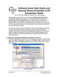
Data Transfer Device (DTD)
Specifications/Requirements:
Mechanical:
3 7/8” W x 5 3/4” L x 1 1/2” D
Electrical:
Operating Voltage: 6V (Four AA Batteries)
Environmental:
Environment: Store Indoors.
Do not get wet.
Temperature Tolerance: 32º F to 120º F (0º – 49ºC)
Software Compatibility:
Hub Manager Professional Version 7.3.1 (or higher)
PC Connection:
USB Port (v1.1 or v2.0) Only
Description
Hand held DATA TRANSFER DEVICE for wireless IR [infrared] transfer of data to and retrieval of the logs from LS2 Series
wireless access control locksets and prox.pad plus IR wireless software managed integrated access system. Data is saved to internal
memory for transfer to a PC via USB connection. Powered by four AA batteries (included).
Software Compatibility
The DTD is compatible with Hub Manager Professional Version 7.3.1 (or higher). The included software CD supports the DTD and
contains the required USB drivers. You can also download the latest version of software at www.ieib.com or update your existing
software through iUpdate.
Note: No additional software is required to transfer data to the DTD.
Packing List
(1) Data Transfer Device
(1) DTD Operating Instructions
(1) USB Cable
(4) AA Batteries (already installed – see Battery Installation Section before use)
(1) Hub Manager Professional Software CD
15.21 Information to User
Any changes or modifications not expressly approved by the
party responsible for compliance could void the user’s authority
to operate the equipment.
Document # 6047011 Rev. 1.1, D2a
Page 1 of 18
Data Transfer Device Operating Instructions
DTD Diagram
Below is a diagram of the DTD. It indications the location of the Power On/Off buttons, the backlighting button and the LEDs. These
are explained in detail in later sections. The Infrared (IR) Port is located at the top of the unit above the display where it says “Data
Port.” When transferring data to the door controller aim the IR Port on the DTD at the IR Port on the door controller.
DTD Battery Installation
Prior to using the DTD, you must remove the battery cover, which is located on the rear of the unit, and remove the red paper tab. This
tab is in place so the batteries are not connected during shipping. First, remove the screw in the bottom center and remove the cover.
Then remove the red tab from the battery. Replace the cover and secure it with the screw.
Page 2 of 18
Document # 6047011 Rev. 1.1, D2a
Data Transfer Device Operating Instructions
DTD Power
To turn on power to the DTD press and hold the ON button. The message below is displayed for two seconds until the DTD powers
up. Note: See the previous section regarding the batteries.
When the DTD is powered-up Main Start-Up screen is displayed as shown below. This message is displayed on power-up until you
connect the DTD to your PC and export data to it from Hub Manager Professional. After exporting, this screen is replaced with the IEI
splash screen.
To turn off the DTD press the OFF button shown in the diagram. The DTD has an automatic power-off feature. After 10 minutes of
inactivity the DTD turns itself off automatically to save battery life.
Display Backlighting
The DTD is equipped with display backlighting. Simply press the B key to turn on backlighting. The backlighting remains on for 15
seconds after the last key press to save battery life. It turns on again after pressing a key. To turn off backlighting completely press the
B key again.
LED Indicators
The DTD uses the green and red LED's to indicate when the device is communicating. When the DTD is successfully communicating
to the door controller, the green LED lights. If at any point you lose communications, the red LED lights. This typically means you've
moved the DTD out of door controller's IR field. You have 10 seconds to re-establish communications before the DTD times out.
Data Transfer Device vs. PDA Operation
The main difference between the Data Transfer Device and a PDA is the way data is transferred from the PC to the DTD. Unlike the
PDA, which requires Palm Desktop software, HotSync Manager and IEI LSLink, the DTD does not require any additional software
and interfaces directly with Hub Manager Professional. In Hub Manager Professional, the data is exported directly to the DTD. Please
refer to the Hub Manager Professional documentation for further details.
Document # 6047011 Rev. 1.1, D2a
3 of 18
Data Transfer Device Operating Instructions
Connecting the Data Transfer Device to a PC USB port
To connect the DTD to your PC USB port, first plug the small end of the 6-foot USB cable into USB connector on the top of the DTD.
Then plug the large end of the 6-foot USB cable into your PC's USB port. The diagram below shows this connection.
Note:
The USB cable uses an A
Plug (large connector) to
a 5 pin Mini-B plug
(small connector).
Important Note:
Do not connect more than one DTD to your PC at a time.
Page 4 of 18
Document # 6047011 Rev. 1.1, D2a
Data Transfer Device Operating Instructions
Installing the USB Drivers
To use the DTD you must install the USB drivers on the PC. The DTD is plug and play, so when you plug it in, your PC should
recognize the new hardware and launch the Found New Hardware Wizard as shown below. Please note that this hardware wizard
runs twice. Follow the same steps both times.
After clicking the Next button, choose the option that says “Search for a suitable driver for my device (recommended),” and click the
Next button.
Document # 6047011 Rev. 1.1, D2a
5 of 18
Data Transfer Device Operating Instructions
Now Windows asks you to specify the location to search for the USB drivers. Choose the “Specify a location” option and click Next.
Windows then prompts your to specify the driver location on your computer. Click the Browse button to search for the driver. For
Windows XP and 2000 choose the following location:
C:\Program Files\IEI\HubManagerPro7\Program\Utilities\USB_Driver\FTDI_XP-2K-2003
Note: The drivers are placed on your computer when you install the PC
software in the folder indicated above. They are also located on the Hub
Manager Professional installation CD supplied with the DTD.
Page 6 of 18
Document # 6047011 Rev. 1.1, D2a
Data Transfer Device Operating Instructions
Determining the USB COM port number
When you connect the Data Transfer Device to your computer's USB port, the PC automatically assigns it a COM port number. You
must then select this COM port in the software to communicate to your DTD. You can either use the automatic search feature in Hub
Manager Professional or follow the instructions below to determine the COM port number. Note: These instructions are for Windows
XP. If you are using a different operating system please refer to the instructions for that operating system.
1.
Right click on the My Computer icon on your desktop and select properties from the drop down list.
Note: If you do not have the My Computer icon on your desktop, you can access the System
Properties by going to Control Panel. Click on the Windows Start Menu and choose Settings,
then Control Panel. When the Control Panel menu opens, scroll down to System. Double-click on
System to open. Follow the rest of the instructions in this section.
2.
When the System Properties screen opens select the Hardware tab, then click on the Device Manager button.
Document # 6047011 Rev. 1.1, D2a
7 of 18
Data Transfer Device Operating Instructions
3.
When the device manager list opens, expand Ports (COM & LPT) by clicking the + symbol. Under this is a list of the COM
ports on your PC. Look for USB Serial Port (COMx) in the list. The COM port is shown to the right. The example below
shows the DTD is assigned to COM4.
Note: If you are unsure of which device it is, unplug the USB cable and the screen will refresh. Take note of which devices
are in the list. Then plug the cable back in and notice which device re-appears in the list.
Important Note:
If you unplug the DTD from the USB port and plug it into a different physical port on the PC or on a
USB Hub, the COM port number will remain the same.
Page 8 of 18
Document # 6047011 Rev. 1.1, D2a
Data Transfer Device Operating Instructions
DTD Menu System
When you first turn on power to the DTD the Main Start-Up screen is displayed. To access the DTD menu system press the ENTER
key, which is the number 5 key in the center.
Next you are presented with three main sub-menu selections: IMPORT/EXPORT, UTILITIES and STATUS. The IMPORT/EXPORT
menu is used to export data to the controller or import transaction logs. The UTILITIES menu contains options to retrieve information
from the door controller, time and date options and communications options. The STATUS menu contains door information, as well
as, DTD information. These menu options are described in more detail in later sections.
To navigate through the menu system, press the down arrow, which is the number 8 key in the lower center or the up arrow, which is
the number 2 key in the upper center. The blinking cursor on the left of the DTD display moves up and down next to the various
options. To select and option press the ENTER key. To move back to a previous menu press the left arrow, which is the number 4 key
on the left center.
Note: If at any time you want to return to the Main Start-Up screen press the * key in the lower left corner.
Also pressing the left arrow brings you back to the previous menu.
Document # 6047011 Rev. 1.1, D2a
9 of 18
Data Transfer Device Operating Instructions
Import/Export Menu
The IMPORT/EXPORT menu is used to export data to the door controller and import transactions from it. There are two options:
AUTO SEARCH and MANUAL SEARCH. These options are described below.
Exporting using the AUTO SEARCH Menu
The AUTO SEARCH option is used to communicate to a door automatically. When communications begin the DTD reads the serial
number out of the door controller and compares that to the serial numbers in the door files stored on the DTD. When it finds the
matching door file, the import/export begins. Note: If a matching file is not found, the DTD prompts you with a warning message.
When you press enter, you are sent to manual search mode, where you select the door from a list.
First, enter your Comm Unlock code on your door controller, then press the enter button on the DTD to select AUTO SEARCH. If
communications are not established you are prompted with the following message (either you entered the wrong code or are not
aligned properly). Press enter to continue.
If a matching door file is found, the following screen appears indicating the name of the matching door it found. Press enter continue
the import/export process.
When the transfer begins the following screen appears and the green LED turns on. If at any point you lose communications with the
door controller, the red LED turns on. You have 10 seconds to move the DTD back into range.
Page 10 of 18
Document # 6047011 Rev. 1.1, D2a
Data Transfer Device Operating Instructions
When the data transfer is complete the following message appears. Press the left arrow to exit to the menu.
If a matching door file is not found, the following message appears. When you press enter you are brought to the manual search
screen, which allows to choose a door from the list. Please refer to the following section discussing the manual search menu.
Exporting using the MANUAL SEARCH Menu
The MANUAL SEARCH option is used to communicate to a door controller that you haven't previously connected to. When you
select this option, the search screen is displayed. To navigate through the list of doors using the up and down arrows.
The doors are displayed as shown below. The site name is on the first line and the door name is on the second line.
Document # 6047011 Rev. 1.1, D2a
11 of 18
Data Transfer Device Operating Instructions
When you reach the door you are looking for press the enter key. If communications are not already established you are prompted
with the following message (either you entered the wrong code or are not aligned properly). Press enter to continue.
Now enter your Comm. Unlock code on your door controller and aim your DTD at the IR port on the door controller and press the
ENTER key.
If the serial number in the export file you are trying to send does not match the serial number in the controller, you are prompted with
a warning message. This message means one of two things: either the serial number in the door file you chose does not match the
serial number of the door controller or this is the first time you've attempted to communicate with the door.
If you wish to proceed, press the enter key to continue. When the transfer begins the following screen appears and the green LED
turns on. If at any point you lose communications with the door controller, the red LED turns on. You have 10 seconds to move the
DTD back into range.
When data transfer is complete the message below appears. Press the up or down arrows to move through the door list.
Page 12 of 18
Document # 6047011 Rev. 1.1, D2a
Data Transfer Device Operating Instructions
Utilities Menu
To access the Utilities Menu press the ENTER button from the Main Start-Up Screen. Next you a presented with three choices. Press
the down arrow to move the cursor to the UTILITIES option and press the ENTER key. You have four choices in this menu, as shown
below.
GET DOOR INFO
The GET DOOR INFO menu item is used to retrieve information from the door controller. First, enter your Comm. Unlock code on
the door controller. Next aim your DTD at the IR port on the controller and press the ENTER key. If successful, the door information
is immediately displayed on the DTD screen. This information includes the door controller serial number, firmware part number and
version, time and date.
SHOW DTD CLOCK
The DTD maintains the current time and date that it receives from the PC. To view the current DTD time and date, select this menu
option. You can only update this time and using the PC software.
Document # 6047011 Rev. 1.1, D2a
13 of 18
Data Transfer Device Operating Instructions
SET DOOR CLOCK
Hub Manager Professional has an option to automatically set the time and date in the controller automatically when you export. You
also have the option to manually set the time and date in the door controller using this menu option. First, enter your Comm. Unlock
code on the door controller. Next aim your DTD at the IR port on the controller and press the ENTER key. If successful, the message
below is displayed on the DTD screen.
OPTIONS
The options menu allows you to set the DTD to the following three options: EXPORT ONLY, IMPORT ONLY or IMPORT &
EXPORT. If you only wish to export data to the controller, choose EXPORT ONLY by pressing the enter key with the cursor next to
that option. When set, the DTD displays a confirmation message. Press the left arrow to exit the message and return to the menu. The
“=” symbol indicates which options is currently set. Select the IMPORT ONLY option when you only want to import transaction log
data from the door controller without exporting any data to it. The IMPORT & EXPORT options performs both operations.
Page 14 of 18
Document # 6047011 Rev. 1.1, D2a
Data Transfer Device Operating Instructions
Status Menu
The STATUS menu has two options. The first displays information about the doors stored on the DTD and second has information
regarding the DTD unit.
DOOR LIST OPTIONS
The DOOR LIST OPTIONS menu is used to view the status of the doors currently on the DTD. The first option SHOW ALL
DOORS displays a complete list of export files on the DTD. This list shows which doors are still pending (ie. Doors you haven't
exported to yet) and which are complete. The second option, SHOW PENDING ONLY, only displays the doors that are still pending.
The third option, SHOW IMPORT FILES, contains a list of all import files currently on the DTD.
To select a menu option move the cursor to the option you want to view and press the ENTER key on the DTD. You are now
presented with the following screen. Pressing the up or down arrow on the DTD moves you through the list of doors.
ABOUT
The ABOUT screen displays the DTD firmware and hardware versions, as well as, the memory capacity. The “2” indicates there are
two memory chips installed, which supports 63 doors. A “3” indicates three memory chips, which supports 95 doors.
Document # 6047011 Rev. 1.1, D2a
15 of 18
Data Transfer Device Operating Instructions
Security Risk Warning (W01)
When the DTD attempts to communicate to the door controller during the import/export process, it first asks the controller if program
mode was entered. If program mode was entered manually on the controller, the following warning is displayed. This warning means
that someone may have programmed data into the controller that doesn't match the PC software database. When this message is
displayed you can either ignore it for the time being and continue with your import/export or you can press the back arrow to cancel
the operation. To correct the situation return to the PC and choose the full export options. Please refer to the PC software
documentation for complete details about performing this action.
Updating the DTD Firmware
The DTD contains a feature that allows you to update the DTD firmware in the field. As new features and enhancements are available,
the new firmware is downloaded to your PC when you run iUpdate through Hub Manager Professional. Please refer to the PC
software documentation for complete details on updating the firmware. If you choose to update the DTD firmware, remember to visit
IEI's website at www.ieib.com to download the latest revision of the DTD Operating Instructions.
Page 16 of 18
Document # 6047011 Rev. 1.1, D2a
Data Transfer Device Operating Instructions
Document # 6047011 Rev. 1.1, D2a
17 of 18
International Electronics, Inc.
427 Turnpike St.
Canton, MA 02021 U.S.A.
Phone: 800-343-9502, 781-821-5566
Fax: 781-821-4443
Website: www.ieib.com
Page 18 of 18
Document # 6047011 Rev. 1.1, D2a