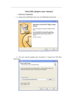
1
USER'S MANUAL
Tips: please read this manual carefully before using, and we reserve the right of final interpretation
LIST
PREFACE
Section 1: Product Specifications
Note
Table 2: MDVR Product Specifications II (Economic type)
Pigure1-1
gViewer
Section 2: Interface Definition and Functions
3G
GPS
BACK
POWER I/O&RS485&RS232
AV-OUT
RJ45
MCU CAM4
CAM3
CAM2
CAM1
Key switch
UN-LOCK
SIM A
SIM
SIM B
SIM
SD1
SD2
UN-LOCK
SIM A
SD1
SD2
SD
SIM
SIM B
Open the key,Left push
the SD card cover
SIM
SD
Installed SD card and SIM card
Figure 2-6 Indicators Illustration
Panel Lights Instruction
AV-OUT Audio and Vedio output
SD1/SD2: Video SD card indicator
light on when the SD card exists
REC: Light on when recording
GPS: Light on when GPS module exists
POWER: Light on when power supply on
ALM: Light on when the machine in abnormal
CAM: Light on when video input 1/2/3/4
has signals; otherwise light off
3G: Light on when 3G communication
module exists
IR: Infrared receiver receives the remote
signal
Example Figure 2-3/4/5: Firstly host keys
must turn to the UN-LOCK position, then push
to open the SD card protection cover, insert
SD card into slot by SD card face up, then close
the protective cover; LOCK: It is necessary to
shut down the electronic lock before normal
starting up,the electronic lock of host is shut
down only when key position twists from UN-LOCK
to another position, and the host will start up
when power on;If twist the electronic lock to
UN-LOCK position when device is under normal
working status, the system will uninstall the SD
card and then extend 3-8 seconds to shut down.
IM card: The host can be inserted by one SIM
card under normal circumstances, two cards can
be inserted when customized, SIM card insert
way: metal side up, notch forward.
GPSAntenna
3G
GPS
POWER
I/O&RS485&RS232
AV-OUT
RJ45
I/O&RS485&RS232
AV-OUT
POWER
MCU CAM4
CAM4
CAM3
CAM3
CAM2
CAM2
CAM1
CAM1
Power Input
Red yellow black
Connect to the
network interface
RJ45
Table 3
The MDVR rear panel interface description as follows
Antenna
UN-LOCK
SD
Right push
Push the SD card cover
Front
Right
Back
GPS Antenna
GPS
POWER
I/O
MCU AV-OUT CAM4
CAM3
CAM4
Power Input
Red yellow black
CAM2 CAM1
CAM3
CAM1
4CH Audio andVideo Input 4PIN
Figure 2-10 MDVR panel interface definition (2)
Table 4
CAM2
The MDVR rear panel interface description as follows (2)
¨
2.6
Simple Instruction for Common Interface Wire
A:Power Cord
As shown by below pictures, one end is a 6PIN white plug, which will be connected to the 6PIN power
input connector on the rear panel of the device, the red and black wires are connected directly to the
vehicle battery or the gathered electric which go through battery and fuse; red wire links to positive while
the black line links to negative, the yellow wire links to firing wire, the main device automatically start up
when the vehicle s key is turned on, and shut off automatically after a delay when vehicle s key is
turned off; yellow wire links to the position when vehicle s key turn on all dashboard lights (the position
before vehicle starts the motor).
Power Line
4PIN Test Line
Alarm I/O
4PIN-AV output line
GPS Antenna
3G Antenna
B:Audio & Video wires
Above are the general ways of MDVR rear plate interface wiring, 4PIN testing wire is only used in the test which
is not recommended to be used in installation, it is recommended to use 4PIN audio and video extension cord during
installation; MDVR need dedicated 4PIN output wires when it is connected to the audio and video output, while the
3.5 Phone Jack interface in the front panel can also output audio and video. Its peripheral interface can be optional
3G/GPS, which then will need to use 3G antenna and GPS antenna, as shown in Figure 2-11
Note
1:Need to make sure the battery voltage is between 8V-36V before connecting, otherwise above voltage
will burn out the device
2:Pay attention to the insulation among the power cord after connection to prevent the short circuit of the
power cord which will burn out the battery and other electrical equipment
in the vehicle
3:It is recommended to link the yellow wire to the firing wire, otherwise the device will not support the
delayed shutdown;
4:The installation of vehicle-mounted is recommended to directly take from battery positive and negative,
or pick from the main electrical with fuse, do not use ground because ground will produce negative pulses
which will interfere with the normal operation of the host. The diameter of positive and negative power
cord must be more than 1.5mm;
C:Alarm input & output
This device has 4 alarm input and one alarm output interface, alarm input detection are all level detection which can
be accessed by a variety of vehicles driving state, such as brakes, steering, keyless entry, an emergency alarm
button etc. Brake, as shown in Figure 2-12, when the brake pedal is depressed, MDVR will be able to detect high
level, otherwise low level is detected. Alarm output are all level output with drive capacity of 200mA, if you want to
access the devices with larger power ratio, it is necessary to use external relay; alarm output photoelectric alarm
wiring diagram in Figure 2-13 as below.
Brake lights
Brake plate
MDVR Alarm output
+24V
MDVR Sensor
Input line S
Figure 2-12
Figure 2-13
2.7 SIM Card Installation
If the MDVR supports 3G wireless communication
module, you will need to install SIM card which is
suitable for WCDMA / EVDO / TD-CDMA . SIM card
is in the front motherboard of the host, when the host
key swifts to UN-LOCK, open the SD card protective
cover to left to expose the SD card slot and SIM card
slot, Metal SIM card face up, and the gap aligned
forward, mouth pressed into place, please remember
to pay attention to the positive and negative as well as
direction when inserting SIM card, after installation,
cover protective cover, then lock keys.
Figure 2-14
2.8 Remote Control Function keys Description
LOGIN
Number key area
Subtraction adjustment
PTZ control
Direction key area
Enter
Exit/Return
System intormation
Delete/Cancel
Play back operation key area
4Images segmentation
PTZ Control Key area
Shortcut key/test key
Table 5 Remote Function Description
When VCR has a password, press the LOGIN button to enter the password, Since the
LOGIN
system does not have restoring or resetting function, please remember the password
INFO
Information Review
FOUR SCREEN- They are used to switch between the four-screen and single screen on the monitor
SPLIT NUMERIC screen; press screen-split key to display 4 screens, press the number 1/2/3/4 to
KEYPAD
correspondingly display channel 1 - channel 2 -channel 3 - channel 4
Return to the upper layer of the sub-menu. Eventually exit the setup menu and
RETURN
return to the monitor screen
PAUSE/STEP
Pause key when play back image & data and single-step play key as well, each
PLAY
press can play one step, press arrow keys to resume normal playback speed
Button of starting play(press this key to play when you have searched and selected the video file)
FORWARD
Fast forward key when play back video data , fourth gear: 2X, 4X, 8X, 16X
REW
NEXT
Rewind key when play back video data , fourth gear: 2X, 4X, 8X, 16X
PREV
Turn to previous page/previous one of searched files
Turn to next page/next one of searched files
PTZ FUNCTION Automatic, preset, recall, zoom +, zoom - focus +, focus - aperture +,
KEYS
aperture -, PTZ PRESET, RECALL, BRUSH
F1
F2
F3
F1 F2 F3 is the function testing key
Section 3: Common quick setting and operation
The host s power cords are red, black and yellow, red and black wires connect directly to the vehicle battery
or go through vehicle fuse, the red wire links to the positive, while black wire links to the negative, yellow wire links
to firing wire ACC (the position before vehicle to start the motor). However, if under other testing environment
without vehicle, following wiring method is needed: twist red and yellow wires to link to the positive, black wire links
alone to the negative, then you can use the switch power supply above DC12V-5A to supply power to the host.
1:When power is supplied after correct wiring, the PWR blue light on the panel will keep on, standby
2:Connect the output wire AV-OUT to display and connect other according devices to the host, make sure the
connection is correct.
3:Need to turn off electronic lock with a key to the LOCK position (required) is the normal starting up,
the corresponding light turns yellow after starting up.
Below Figure 4-1 is testing wiring, as well as the the power supply wiring during actual loading.
Yellow line
Black line
Only used as a test wiring
Red line
-
Car circuit
control
Connection diagram
Car battery
1 The power supply voltage input range is DC8-36V, when there is only a blue light on, it is
a standby state which is not really starting up; more than one light will be on under normal
start up status.
Note 2 The host can not be delayed shutdown when you use testing wires for the power supply of host.
Need to use input method when input text, such as the company name, license plate number, driver's name, line
number, and other text input needs when requires input method under other menu. Take inputting Yue B95886
for example after entered the input interface to illustrate the input steps
Step One: in the state of Chinese input, as shown in Figure 4-2, Character YUE(GuangDong) s Pinyin is YUE,
move the cursor to press ENTER key to input the first Chinese letter y, it will display the corresponding PinYin
combination 1-5, if there is no PinYin as YUE, please press the FWD key on the remote control to the next pages;
when it shows 1.you 2.yu 3.yuan 4.yue 5.yun on the next page, please press the number 4 on the remote control
which will show 1-5pcs of Chinese characters, if there is no YUE character, please use FWD button to turn the
pages; when it shows 1 read 2 key 3 Yue 4 Guangdong Yue, please press 4 to input the first Chinese character
YUE(GuangDong).
Step Two: Now you will need to input the letter B, move the
cursor to pressENTER key to switch the input method
to the state of capital letters, as Figure 4-3, then move the cursor onto the letter B to press ENTER key to input it.
Step Three: Next you will need to enter numbers, press it again to switch to Chinese input state, you can not input
numbers under Chinese input state, then you need to move the cursor to the "in (middle)" word, press ENTER key
to turn to EN, and then enter numbers 95886.
After the completion of above steps, press the RETURN key to go back and save, other text input under other
menus will be more or less the same. Please press CANCEL to delete it when there is a typo during the input process.
3.3 Video settings
1 Video Start Up
After the installation of a new SD card in the device, the formatting is recommended after normal
boot into the system, in order for system to have better compatible relationship with its format. After
the formatting, host will automatically start up the video when restart.
2 Timer recording
Firstly modify to be timing video under the System menu - Video Settings - General Settings - Video
mode, save and return to the previous menu level to be video plan, and then set the time period of the
video; save it after setting finished.
3 Alarm recording
Firstly modify to be alarm recording under the System menu - Video Settings - General Settings - Video
mode, then set the alarm pre-record time (range 0 -60s) and alarm video delay (30-900s); alarm output
delay (5S-255S), which can be set according to the actual external alarm device.
Secondly it is needed to install the corresponding external alarm input device, such as the emergency
button set by sensor, power switch for open/close door, brakes lights and other sensors; the following are
the several main alarm settings of this device:
A:The sensor input alarm system, system menu - alarm settings - sensor settings
Set the menu (in Figure 4-21) with high or low trigger level, and then turn on the alarm; this menu is
corresponding with four external alarm input SENSOR IN (which can be for eight external alarm output),
it must be connected to the corresponding external sensing switch device, such as door-magnet power
supply, emergency button, turning signal switch, brake lights (Figure 2-12), etc; rough connections are
shown in Figure 3-4.
Connect the the host back panel alarm interface
External level input
External
sensor switch
B peed alarm setting system menu - alarm settings - speed setting
If the vehicle selects the GPS to get speed information which requires normal status of the GPS signal, then
we need to set a high threshold speed limits, such as 100km / h that is the maximum speed limit, alarm is
opened when vehicle is started;, vehicle will output alarm when the vehicle speed exceeds 100KM / H
If you choose to obtain speed information from the vehicle, it must be connected to the speed pulse sensor,
which is used to calculate the speed ratio (coefficient = pulse/speed), the pulse sensor is connected to the two
wires SPEED-A and SPEED-B of our device, the speed ratio will be measured according to the set speed and
pulse during vehicle s moving, which is a little complicated to operate; simple wiring in Figure 3-5.
Pulse sensor
C
The acceleration alarm recording
system menu - alarm settings - acceleration
Impact acceleration can be understood to be for a three-dimensional XYZ coordinate axis which can denote
three groups of status---up and down, left and right, front and rear; the bouncing up and down, accelerate,
Emergent brake, rollover, sharp turns, etc. during the moving process of the vehicle can all be expressed in
XYZ. Threshold needs to be set by an associated value, it is firstly needed a calibration after the installation
onto the vehicle, the calibration means to clear parameters X / Y / Z, secondly measure the allowed range of
emergent brake & acceleration & bouncing up and down as well as the change value of a sharp turn of the
vehicle during the operation, thereby to determine which axis s value changes a lot. These run status will be
in real-time display and change. After setting the threshold, when the vehicle runs exceed above threshold,
the alarm will be uploaded if the "alarm" opens.
D
Motion detection alarm recording
System Menu - Alarm Settings - Motion Detection
Turn on the motion detection enabled switch, set the sensitivity level of high, medium and low based on the
need, general settings is medium, and the next step is mostly to set the sensing area of the motion detection,
motion detection area will use diagonal set, please refer to Figure 4-30. As long as you set the motion
detection area and set the video mode as alarm recording, the image move will trigger the video to generate
alarm recording files (Note: it can only take effect after setting and saving)
Setup steps
Firstly, select the PTZ protocol: divided into PELCO-D and PELCO-P protocol, most of peoplewill choose
PELCO-D
Secondly, set the baud rate: there are four options 1200/2400/4800/9600 which must be corresponded with
the baud rate on PTZ
Thirdly, set the address code: directly input the address value corresponding with PTZ setting, corresponding
is required. Generally the defaulted PTZ address code is 1, PTZ address code has adjustable DIP, it is needed
to set different address codes to identify when there is many PTZs.
Fourthly, wiring: Connect control wire 485 on the PTZ to the RS485-A positive pole, connect the other one
to the RS485-B negative pole.
First way: the remote control PTZ wiring
GPS
I/O&RS485&RS232
AV-OUT
Video
The power input of the PTZ
After wiring and parameters setting of PTZ, users can only use remote to control PTZ after
selecting the channel access to PTZ, for example, if PTZ connects through channel 2, then
Note you need to switch to channel 2 maximize on the monitor interface to control it.
Second way: with a three-dimensional
keyboard control PTZ
GPS
RS485
Connection Key
3D Key
Video line
The power input of the PTZ
Fifthly, there are three ways of wiring, the first way is connecting the 485 control wire to the wire 485A and
485B on host, connecting the video cable to the host video input and then provide power to PTZ; this kind
of wiring needs to set the MDVR host data be corresponding to PTZ data, and then use the remote controller
or platform to remotely control PTZ.
The second way, the head of the 485 control wire directly connect to the three-dimensional control keyboard,
do not need to connect the MDVR host, the video cable connects to the host video input, separately power
supply to the PTZ and three-dimensional keyboard, and then set the keyboard parameters to be corresponding
with PTZ. This wiring way is the most practical one, because it uses three-dimensional keyboard to control
PTZ, which is faster, easier and more practical. It is recommended to use this way to install PTZ
The third way is to connect to both car host and three-dimensional control keyboard, so that both can be
controlled and platform remote can also be controlled.
Besides playback by the host side, video files can also be copied to your computer to be played by the player.
Install the player
Double-click the installation file named MDVRPLayer V1.0.1.exe in the CD-ROM, and then select the
installation language (supporting Chinese and English), click OK and then keep clicking 'Next', a player
shortcut icon will show on the desktop after installation completion; installation steps shown in Figure 3-7
Remove the SD card from host and insert it into the card reader, then connect it to the computer's USB port,
the computer automatically recognizes the newly installed hardware; video files are stored in the form of
date folder, open the folder to display video file, video files are named with suffix ".264"
As shown by Figure 3-8, the screen show of playing the file in Figure 3-9
Playback
channel screen
Play the file list
MAP
DSPLAY
STOP/PLAY/PAUSE
/FULL SCREEN
MULTI-SCREEN, CAPTURE,
AVI CONVERSION, SYSTEM SETTINGS
Note: The following described iS invalid to the host which is without 3G module, it is not needed to report to gServer platform
Step 1: Install the SIM card, 3G card which supports WCDMA / EVDO / TD-CDMA, detailed installation please refer
to Chapter II, 2.2, and 2.7
Step 2: Enter into the system menu after starting up, firstly modify the host s device number, System Menu General Settings - Vehicle Information - Device Number, device number range is from 00000 to 99999. Server
identifies the host according to the device number, so it is very important to modify the device number.
If the modified device number cannot be reported sometimes, please check the server device number has
been used or not.
Step 3: Modify the vehicle identification number; the vehicle information displayed on gServer platform is based on
vehicle identification number. If it is not modified, it will display 00000 in default. If all are in default, it would cause
inconvenience to find vehicles. So it is proposed to modify the vehicle identification number.
Step 4: Enter another menu settings, System Menu - General Settings - Network Settings, set the server IP and
control port, the server
can be self-built, and can be affiliated to the manufacturer s server as well, enter the server IP and control
port, which is typically 6608, the save by end.
The main process of gServer quick reporting is as Figure 3-10 below.
Installing
the SIM card
Modify the
device NO
Modify the
license plate
number
Setup the server
address and port
3G settings
gServer manage
User name assigned
add vehicles
Step 5: Enter the system menu - peripheral - wireless broadband, which is with wireless settings inside.
A:wireless 3G settings
Please pay attention to the supporting type of network during wireless 3G setting: WCDMA, EVDO and
TD-SCDMA. Also note the access point and the center number, The user name is in default in domestic
which is basically not needed to modify, however there is also in some domestic places he 3G card needs
to be entered by user name and password, and some foreign operators will need to enter user name and
password as well, the access point and the center number will need to be modified too, which is required
to input relevant information according to the local network data. You can press INFO key to query whether
dialing is successful or not after setting.
ENABLE
TYPE
APN
CENTER NUM
USER NAME
PASSWORD
ENABLE
TYPE
APN
CENTER NUM
USER NAME
PASSWORD
C:local IP settings
Local IP setting is the setting after the RJ45 port access
the network cable, set the local IP and central server
number to make it be linked from local area network to
WAN through the network cable, which can also report to
gServer server platform.
ENABLE
TYPE
TD-SCDMA
APN
CENTER NUM
USER NAME
PASSWORD
IP ADDA
NERMASK
GATEWAY
MAC ADDA
SERVER IP
CONTROL PORT 6608
Step 6: Previous steps are the network connecting ways. When the network is connected, the next step is
the operation of software management on the PC gServer, which is divided into two steps. One step is the
gServer Manage username allocation and vehicle adding, if it is a self-built server, this work can be done
internally; if affiliated to manufacturer s server, this will need assist from the technical staff to add. The other
step is to log in gServer Client by user name to review, which ultimately achieves gServer reporting, please
refer to the CD-ROM gServer technical documentation for client's detailed operation
Section 4: Menu function instructions
4.1
Device Start-up and User Login In
After host is installed in vehicle environment according to the installation instructions, start it up by
ensuring that power supply and other external devices are connected properly, normal start-up screen
as Figure 4-1. The machine starts to enter the normal quad monitor interface, as shown in Figure 4-2.
REC
REC
REC
REC
Press the LOGIN button on remote control to go directly into the login screen as shown in Figure 4-3
Description:
1.Device No.: user set the unique device number to each device, which will automatically display on the right
of the ID input box , it is required for unique device number for the same server, device number modifications
please refer to section 4.3-2
2.Username: Include administrator and operator, the Administrator has the authority to operate on all menus.
Operator has only view permissions.
3.Password: Enter the appropriate password according the selected username, select down key to move to
"OK" and press "ENTER" to log in when the password is correct; when password is incorrect, prompts login
password error message, press OK to reenter the password. The initial password for administrator is 111111.
The system menu interface after login is as shown in Figure 4-4.
00000 (00000)
CAUTION
password is error
Date,Time,Vehicle,User etc.
ENTER
The system menu includes seven main menus: General settings, video settings, alarm settings,
system tools, peripherals, video search, system information; as shown in Figure 4-4
1
Note
2
3
All of the following sub-menu settings must be confirmed to [save] to take effect,
otherwise the setting is invalid.
The check box
filled means this function is selected, unfilled means it is not selected.
Numbers can be inputted directly by the number keys on the remote control or using the
soft keyboard. Letters input must be completed through the soft keyboard, Press
“RETURN" for submenu to go back.
4. 2 System Menu Organizational Framework
DATE&TIME
GENERAL
VEHICLE INFO
USER SETUP
NETWORK
NORAL
RECORD
CODING SETUP
SUB-STREAM
RECORD PLAN
SENSOR
SPEED
LOGIN
ALARM
G-SENSOR
TEMPERATURE
MOTION DETECTION
CONFIGURE
TOOLS
Default password:111111
SEARCH
PERIPHERALS
SYSTEM INFO
FORMAT
LOG
PTZ SETUP
WIRELESS SETUP
WIFI SETUP
SD/HDD STATUS
DEVICE STATUS
4. 3 G eneral settings
Date,Time,Vehicle,User etc.
System encoding,Recording time etc.
General settings is the first menu in system menu, the generic setting interface contains four function
options: date and time, vehicle information, user management and network, as shown in Figure 4-7.
Set the system time and some other basic properties of the device, as shown in Figure 4-8
1 Date Format: Press "ENTER" drop-down menu to use the arrow keys to select the output format of date
(year-month-day, day-month-year, and month-day-year).
2 The date and time settings: two ways for time proofreading ---GPS time proofreading and manual time
proofreading, when select GPS time proofreading, the modified time will change because of reaching the GPS
time proofreading point, so if you want to modify the time, it is suggested to choose manual time proofreading
mode, which can be in normal after modifying time. Way of modifying the time and date: move the cursor to the
number which needs modification and directly press the corresponding number keys on the remote control,
press the save button after set.
3 Operating timeout: three options--1 minute, 5 minutes, 15 minutes for choosing to set how many minutes
later will automatically exit the menu after entering the menu. General settings menu interface
General settings menu interface
4:When the GPS time proofreading opens, in the default time
zone, such as the default GM +08:00 time zone, system will
automatically proofread time by GPS when it reaches time
proofreading point.
5:Switching machine: the ignition mode / timer mode, the
ignition mode is that MDVR began to start up after vehicle
starts its key, this operation is recommended as the preferred
default starting-up. timer mode is the operating mode of startup
and shutdown at the point of time set by the user.
6:Off delay: Either the ignition mode or timer mode, as long
as the wiring is correct, you can set the delay off of host,
delay off time range is from 5 minutes to 180 minutes, MDVR
will continue to do the video recording by the delay off set
time before shutting down when the vehicle is turned off.
4. 3-2 Vehicle settings
1:Device No.: user sets a unique device number to each device,
which will automatically display on the right of the number input
box. The device number is 5 digits & characters, digits are
effective. If it is 3G device, it is strongly suggested to set a unique
device number, because a server requires only one device number.
2:Vehicle identification number: this number is recommended
to be set during installation, because the vehicle identification
number will be superimposed onto the video during video
encoding to be strong video evidence. If you do not enter the
vehicle identification number, then it will show 00000 in
default. For detailed input method, please refer to Chapter 3.2
3:Line number, company name, the name of the driver can
fill out as demand
assword setup interface is shown in Figure 4-10
1.Password effective settings to select on or off
2.Only administrators have permission to modify the passwords
of users and administrators. Ordinary user s password is initially
set as 000000, and the initial password for administrator is 111111.
When password change finishes and exit menu, it will need to use
new password to log in again, the login screen shown in Figure 4-3.
Network setup interface is shown in Figure 4-11
1.IP address Mask Gateway etc are LAN network setting after
plugging in the network cable, there is no need to input if you do
not use them.
2.Server s IP address is the one MDVR host using 3G to report to
gServer platform central server, which generally is the public fixed
IP, the IP address must be set up, or else 3G host cannot report to
platform; this requires our host can support 3G; this menu will no
need of setting if the host is without 3G module.
3.Control port: set to be the port number of the gateway server,
generally the default is set to "6608" port
It is divided into four video settings menu, General Settings, encoding settings, sub-stream settings and
video programs.
The MDVR needs settings in order to achieve the best video, video will start work after host start up in default,
but in order for better video function of host, the relevant parameters can be modified. Video setting menu
shown in Figure 4-13
system encoded Recording time etc
TV System,Record Delay,Alarm Delay
Description
1.Selectable video format PAL / NTSC
2.Selectable video mode: startup recording / alarm
recording and timer recording
3.Sectional Time options 15/30/45/60, that is to say, video
file will be packaged per such period of time, due to the
limitation of the SD card writing speed and to make the
packaging of the video file segments faster, it is
recommended to choose 15/30 minutes.
4.Automatically overwrite can be selectively turned on / off,
when it is turned on, video file will automatically overwrite
the earliest video when SD card is full.
5.Alarm pre-recorded time: when the alarm occurs, it will
package the videos happened before alarm occurs to alarm
recording (range 0-60S)
6.The alarm recording Delay: when the alarm stops, it will package the videos happened after alarm stops to
alarm recording (delay range 30-900S) to form an alarm recording file.
7.Alarm output time: the continual alarm output time after the alarm occurs and connects to external alarm
device: output time(5S - 255S)
8.Protection time of alarm recording, that is, storage time for alarm recording in SD card, in the protective
period of time, even if the SD card is full alarm recording will not be overwritten, and the drop-down menu
optional 1/3/5/7/10 days, it is recommended to set 1 or 3 days according to the current capacity of the SD card.
All Channel Encode Setup
Encoding settings interface as shown in Figure 4-16
Definition: Optional D1/HD1/CIF; Frame Rate: PAL is adjustable 1-25 frame, full frame rate of 25 is real-time
video; NTSC is adjustable 1-30 frame, full frame rate of 30 is real-time video.
Quality: optional level 1-8, among which level 1 is with the highest quality while level 8 is the lowest; quality
setting will directly affect the effect of video playback. Under the same resolution, the higher quality level is,
the clearer display effect it would have, of course, the video files will take up relatively large space. When some
channels do not need video which means no need of video or recording, the channel switch can be closed in
order to save the storage capacity of the SD card.
Recording: here the volume is the volume switch for device recording, when the channel is connected with a
pickup, it can open the recording of the channel.
Preview: Preview is open by default, the function of preview is to make video normally show in the channel,
if you turn off the preview, then the channel image cannot be seen, but in fact the image is still there and be
video recorded.
Sharpness / resolution
Quality
Bad
8
7
6
5
4
3
2
1
PAL
Good
NTSC
Sub-stream is important parameters when the video, audio and data are uploaded to the network via 3G, as
shown in Figure 4-17, and its settings is related to whether the video displayed on gServer platform is clear
and smooth. Of course, the most important factor for network transmission is the up and down rate of the local
network broadband. Video resolution can be set as CIF and QCIF.
1.The corresponding relationship between bit rate setting and the frame rate changing is shown as below,
the bit rate set here is the transmission rate of a channel.
2.The frame rate setting is changed according to the corresponding bit rate change; it can be set as bit rate
96 frame rate 10 in default. This setting is the current one that can guarantee fluency as well as a certain
resolution when 3G network transmits
audio and video, but you can set this based on your own network situation, if under good enough network
bandwidth , it can be set with higher frame rate and bit rate and it can also be set automatically.
Bit rate
Frame rate
Sub-stream set is a basic set of network transmission
SUB-STREAM SETUP
RES.
RECORDING SCHEDULE
DATE
SUN.
00:00:00
MON. 00:00:00
TUES. 00:00 :00
WED. 00:00 :00
THURS. 00:00 :00
00:00 :00
PRI.
00:00 :00
SAT.
EVERY. 00:00 :00
FPS BITRATE
96
SAVE
TIME 1
23:59:59
23:59:59
00:00 :00
00:00 :00
00:00 :00
00:00 :00
00:00 :00
00:00 :00
TIME 2
00:00:00
00:00:00
00:00 :00
00:00 :00
00:00 :00
00:00 :00
00:00 :00
00:00 :00
00:00:00
00:00:00
00:00 :00
00:00 :00
00:00 :00
00:00 :00
00:00 :00
00:00 :00
SAVE
1:f you select timer recording mode in "video mode" as shown in Figure 4-14, you need to set what
the timing period is.
Figure 4-18, move the cursor to the required time period; press the number keys on the remote
control to input. Timer recording mode is not commonly used, customers can use it according to the
actual situation, most of customers still choose the starting-up recording and alarm recording.
Alarm settings menu includes settings of sensor, speed, acceleration, temperature and motion detection, etc.
IO,Speed,GSensor,Motion,Temperature etc.
IO Sensor Alarm Setup
1.Users define the sensor name according to the
different setting interface when install MDVR; take
Figure 4-21 for example, to modify the name "INPUT"
to be Chinese 'front door, brake', you can press the
'ENTER' key and then input under the soft keyboard
Chinese input state; for specific input method please
refer to the similar methods in Chapter 3.2.
2.Enable opens means start the sensor, the host
has 4-channel sensor input; these alarm input is
generally connected onto the circuit of vehicle,
such as door switch button, brake lights, turn signals,
etc., sensor input with high level is effective, users
generally use above 5V to form back road, please refer
to Figure 2-12 in Chapter II 2.6 for schematic diagram.
Speed Sensor Setup
1.There are two choices of speed source "GPS" and "vehicle", if you select GPS, then the speed
information of vehicle can only be transmitted to the device under the situation that device has
GPS module and GPS signal, the vehicle can obtain the speed of the vehicle via GPS.
2.If you select the "vehicle" to get the speed, you will need pulse sensor to calculate the speed
ratio (coefficient = pulse / speed), pulse sensor links to the two cords SPEED-A and SPEED-B
on device port, and the speed ratio is determined according to the set speed and obtained pulse
during the vehicle traveling.
3.The speed unit KM / MPH is switchable, the high speed limit threshold is the maximum speed limit,
if alarm opens, the vehicle over speed alarm can also be seen on the platform.
GSensor Alarm Setup
As shown in FIG 4-23, it must be calibrated before setting acceleration, the calibration is clearing up X / Y / Z
parameters. The acceleration can be understood as a 3D X / Y / Z axis, respectively stands for three-group
status--- up and down, left and right, front and rear, the uniform is useless, the acceleration setting mainly
set the threshold, which needs to be determined. Generally speaking, the instantly acceleration is relatively
large when vehicle is under emergent brake, crash, acceleration and sharp turns situations, the intuitive
reflect is the relatively large threshold beating which is in waveform display of three state X \ Y \ Z when
playback on PC.
Temperature Alarm Setup
1.emperature has two kinds of unit Celsius
C and degrees Fahrenheit F
2.The temperature returns onto the device via temperature sensor, as long as you set the temperature
alarm threshold and it begins to be enabled. When the temperature is higher than the threshold, the
device will release alarm, and it can be transmitted to the center gServer platform to record the alarm
information after alarm function is turned on.
Motion Detection Settings
Select the motion detection under alarm settings module to enter the motion detection settings interface,
as shown in Figure 4-29
Within the area selected by the user, the system will release alarm information after detection when there
are moving objects. The motion detection alarm events can be searched in the log with the name CHL MD Alarm,
the user can review these logs under the System Tools - log search. When the channel acts as motion
detection, the video of the channel will be packaged into alarm recording, which users can search and play
back the videos during that period of time.
Motion detection area setup steps
Select the "Settings" and press ENTER on the remote control to enter the motion detection area setup
interface, as shown in Figure 4-30. Firstly: select the first box (yellow), which will turn blue after pressing
"ENTER", secondly: select the second box and press "ENTER", the rectangular area which takes the two
box as diagonal is selected; Thirdly: "RETURN" to the higher level interface and save.
Sensitivity is divided into three levels-- low, medium, and high. Under high sensitivity state, it is capable
of sensing changes in light, while under the low sensitivity state, only can detect the moving objects;
customers can set the sensitivity level according to the actual situation.
It is divided into four menus under System Tools: configuration management,
device formatting, system upgrades, log search
Config Manage,Device Format,Upgrade etc.
Storage Device Format
FORMAT SD CARD
CAUTION
SELECT SD
BE SURE FOR FOTMAT?
OK
CANCEL
Formatting is successful, the system will restart
FORMAT
Formatted SD card operation
Start up after installing SD card, please format the SD card under normal circumstances, the formatting steps
are as the above
charts, then press "Format" button to choose whether to format by the pop-up boxes. It will remind the successful
formatting after formatting finished.
WARNING: Formatting will delete all the data storage on the device, please confirm whether there are other
documents and important information when do the first-time formatting.
Config File Manange
Configuration management are mainly the importing and exporting system settings and the factory resetting;
when execute exporting current configuration, the system will store the configuration information on the MDVR
into the SD card, if other MDVR s configuration is the same with this device s configuration, then this SD card
can be inserted into other MDVR to be executed by importing current configuration.
Restore the default settings: when you can not find the cause of the malfunction in the system which is
set incorrectly or by artificial error, you can execute the restore default settings:, and then re-set the relevant
parameters of the host, it will be asked to reboot the host after restoring the default settings.
Log Search
Log Search Results
Select start & end time, and select the type of event: all types, alarm log, system log, operation
log before searching, the system will record the relevant information, such as system boot, user login,
user settings, network settings, video loss, playback files, motion detection alarm, system settings,
and other information.
UN-LOCK
SIM A
SD1
SD2
SIM
SIM B
SIM
SD
Upgrade steps are as follows:
Step 1: copy the "xxx.crc" upgrade program files to the root directory of the SD card, do not need to build any
folder, copy directly to the SD card inside;
Step 2: Insert the SD card into the SD card slot of the host, then power supply to the host, when host starts up,
it will be prompted to enter the "Upgrading ..." interface upgrade, which will last about 1-2 minutes.
(The equipment did not shut down, connect the device shutdown!)
Step 3: after the success of the upgrade, the system will automatically enter monitoring four split screen.
Press the INFO key on remote control to view system version information.
Note
1: During the upgrading process of host, do not power off or unplug the SD card, otherwise
it will cause the system to crash;
2: Another upgrade way of host is remote upgrade through the gServer platform;
3: When the device does not start because of host s upgrade misuse, it can only be
suggested for depot repair;
4.7 Peripheral
Peripheral settings includ the PTZ setting, wireless broadband and WIFI setting.
PTZ Parameter
1.Agreement: divided into PELCO-D and PELCO-P protocol
2.Baud rate: 1200/2400/4800/9600 four options, user can modify to different baud rate depending on different
PTZ settings.
3.data bit: data bits is generally to be 8, where you can select from 1 to 8, generally is 8 in default.
4.Stop bit: Stop bit is generally to be 1 which is no need to modify in default.
5.Parity: parity bit is to choose what kind of checking way, which is generally chosen None.
6.Address Code: The address code is directly input by the address value which is corresponding with PTZ
setting, they must be set in correspondence. Generally many PTZ set default address code by 1, PTZ has
adjustable address code DIP, and it needs to set different address codes to identify when there are many PTZs.
7.Wiring: PTZ positive pole connects to RS485-A, negative pole connects to RS485-B.
After setting the related parameters of PTZ, PTZ can only be controlled by remote control after selecting the
channel to access PTZ, for example, if PTZ connects through channel 2, then you need to switch to channel 2
maximize on the monitor interface to control it. For details, please refer to Chapter 3.4
Note
To the selected channel to access PTZ PTZ related parameters set with the remote control PTZ,
for example PTZ pick on Channel 2, then monitor the interface you want to switch to a 2-channel
to maximize in order to control it. Details, refer to Chapter 3.4
Description: When the MDVR will use 3G network to report to platform, related network settings in this menu
should be done.
1.Insert the appropriate SIM card according to the communication configuration of the machine, supporting
three: WCDMA (China Unicom) , EVDO (China Telecom) and TD-SCDMA (China Mobile). SIM card slot is
on the front panel, with a key to unlock it and open the protective cover by left, you can see two interfaces
SIMA and SIMB. In regard to the SIM card installation, please refer to the second chapter of this manual 2.2
Figure 2-5, or the reference figure as follows.
2.Installed SIM card and then plug in the 3G antenna, to ensure that the
system is able to receive good 3G signal.
3.Edit the following information on menu interface of wireless broadband :
A: set the module enable to be open.
B: select the type of communication, if the machine supports WCDMA
type, then select
WCDMA; if supports EVDO type, then select EVDO; Press "ENTER"
key to switch (it is decided by models whether it supports WCDMA /
EVDO /TD-SCDMA, each model only support one type, because the
internal module is unique.)
3G
3G wireless setting.
: domestic access point and the center number is generally in default, do not change; username and password
in some provinces are not in default, and some do not need to enter which means they can be empty, most of
the time use the settings in default will be ok. In regards to foreign 3G, it would need to be set according to the
access point and the center number provided by operators, in some places abroad it must be entered by a user
name and password for normal dial-up; When your host can not report, please make sure your 3G settings are
correct (most of foreigners use the WCDMA device).
D: All set up needs to be saved.
4. Exit all menus, press the INFO button on the remote control, which is able to see the information of 3G
communications, if the signal is good, it will display dial-up success, then the device can be reported to
gServer platform with the server IP address settings, port settings, device number settings.
5. In regards to details of the three steps of reporting to gServer servers, please refer to Chapter 3.6.
Instructions:
Insert WIFI antenna to corresponding interface behind the host, edit the following information on WIFI setting
interface as shown in Figure 4-48:
1. Set WIFI enabled and encrypted to be open. Authentication modes includ WPA, WPA-PSK, WPA2-P
SKOPEN and SHARED, with encryption type TKIP and AES; authentication mode is not in force yet, so only
by selecting OPEN status (that s, open status does not require authentication) the WIFI can carry out normal
communication, select the type of WEP encryption, which of course should be consistent with the encryption
type of your router, as shown in Figure 4-48;
2.Enter separately the SSID and password (name and password of wireless network), and set up IP, mask
and gateway, this setting needs to be in the same network segment as your current wireless LAN network
settings. SSID / password can be set by pressing "ENTER", IP, mask and the gateway can be set by pressing
the number keys;
3.View system information, shown in Figure 4-46, if the WIFI signal value is greater than-60db, then it
means a relatively good WIFI signal.
4.If you want to report to the gServer server, please input gServer central IP and port number into the
central IP field shown in Figure 4-11.
Note
The functionality of WIFI depends on the model, and this feature is optional, therefore,
the mode to realize WIFI menu function may not be the same, which is subject to the
actual development of the function.
Record file search,playback
Enter into the video search menu, play back video files by searching for different video types (all
types, conventional types, alarm types) and different storage media (SD1 and SD2). Specific files can
be searched by date and time, when there is vedio files some day, the corresponding date will be
displayed in green, as shown in Figure 4-50; searching results will be displayed after searching as
shown in Figure 4-51.
Enter into the search results interface to display the related information of video file:
Firstly, there are two types-- "conventional" video and "alarm" video, conventional video is generally
the video files recorded after setting up the start recording or timer recording but no alarms have occurred,
while alarm video occurs when the host occurs alarm or alarm is input from external which cause host to
record video files, for example, sensor settings, speed alarm settings, acceleration settings, motion detection
settings have all been set parameters inside, and also connected to the peripherals externally, when the
alarm signal is generated, the system will record the alarm file.
The resolution refers to the resolution of the video playback, which has three kinds D1/HD1/CIF; the
starting time and ending time of the video file is the packaged time; and it will display the file size of the corre
sponding channel in behind, the file size has something to do with the resolution, video packaged time and
quality, for detailed package file size, please refer to Appendix 3.
Playback time display
License plate number display
Playback vehicle speed display
Playback GPS
information display
to play,as shown in
When the video file is selected, it will be highlighted in blue, press
Figure 4-51 and 4-52, the playback time, the history of the vehicle speed, GPS information and
so on will be played during process. Commonly used keys are PLAY
Forward FWD
,pause PAUSE / STEP
, stop button STOP
playback; speed degree fast-forward and rewind can both use
, rewind REW
, Fast
, and "RETURN" key during
2,
4,
8,
16 times the
speed to play; if there is invoice during playback, the volume can be adjusted by pressing the
arrow keys to the left or right after maximizing the channel; it can return to the search results
interface during playback at any time by pressing the "RETURN" or "STOP". For the remote
control s function please refer to Chapter 2.8.
Moreover, in regards to the playing of video files in the SD card on computer, please refer to
Chapter 3.5.
Storage Device Info
Description:
System information played a significant role in
viewing the device s status, it is very useful for
the installation, commissioning and failure
determine of the device. Firstly log into the system
menu, the last one is System
Information ,
/ HDD Status
which has two menus named SD
menu and Device
evice Status menu .
SD / HDD Status menu displays the related
information, the total capacity and remaining
capacity of SD card after entering.
Device Status View of System Information:
Under the status of four-screen monitoring on site, press the "INFO" button on the remote control to directly
display device status information as shown in Figure 4-57, which includes the version information of
hardware, software and the MCU, and will display related information of GPS module, WIFI module, 3G
wireless module and SIM card at the same time. Device status information will be often used in viewing of
system status and fault judgment. For example, when you use 3G to report to gServer server platform, here
the status of 3G card signal and dial-up can be displayed intuitively, and here can also display whether the
connecting to the server center is successful or not.
Appendix 1: gServer platform interface
VEHICLE
SELECTION
MAP
PTZ
CONTROL
VIDEO DISPLAY
AREA
VEHICLE INFORMATION
STATUS
Appendix 2: Common problems and treatment
Q: What can I do when I found a problem with the product, but I can not solve it by myself?
A: Take note of the model and software version number, then submit a detailed description of the problem
to the technicalsupporting engineers to analyze; the more detailed you have submitted,
the more convenient for us to analysize.
Q: How about when there is no video output from the vehicle host device?
A: 1.Check the host s turn-on status, if only a blue light on, it means the host is in standby status and has
not been started up yet, meanwhile check whether the host s power cords red & yellow cords are in power
supply status or not, if only one cord is supplying power, the device is unable to start up.
2.Check the power supply status of display screen, as well as check whether the display video has been
switched to AV status.
3 Check the connecting status between the host s video output cable and display screen.
4 check whether the lock status of the host s LOCK, it must be locked before normal starting up.
Q: How to do when the car host video input interface is different from the camera output interface?
A: The car uses 4PIN type while camera uses BNC or aviation head type, if not in correspondence, please
use conversion head for connection or wiring based on standard corresponding according to
the cable sequence defined by the car host.
Q: How to do when the device does not conduct video recording after it is turned on and SD card
has already been installed?
A: 1.Check whether the SD card has been formatted or not after installation, because unformatted SD card
cannot be used. Enter System Menu - System Tools - Device Format to format the newly
installed SD card;
2. Check to see whether video channel is closed or not, whether set a timer recording or not, it will not take
video when it is not within the video recording time period.
3.Check the SD card inserting status and whether the SD light on front panel is on or not.
Q: The video file is missing or there is no video file within a certain period of time, how to do?
A: 1. Determine the time period by analyzing the final video file before missing and the first video
file after recovery.
2. Confirm whether the host is not on during that period of time, such as when the driver halfway
parking, loading and unloading goods while the host is not set by video delay.
Q: When car PTZ cannot be controlled, it cannot rotate up and down, how to do?
A: Check whether PTZ protocols and baud rate are set correct, address codes are corresponding or
not, whether have selected to maximize the video of the channel when control the PTZ, for example,
when control the second channel, it must maximize the screen of the second channel image to control it.
GPS-related issues
Q: GPS module exists but no coordinate information?
A: 1.Check whether GPS module exists, if it does not exist, check whether the hardware is installed or in
a good contact.
2.Make sure that the GPS antenna contacts are good, whether the antenna is broken, it is recommended
to be located in places with strong signal, note that some car glass shielding film will block GPS signals;
3 If the test is in the room, the signal of GPS antenna in the room will be obscured, it is recommended that
the GPS antenna is placed outdoor.
Q: Deviation of GPS location on map?
A: It means the signal is valid if the GPS module already positioned, there may many reasons for the deviation,
such as government restrictions, permissible error, GPS signal interruption, etc; the actual satellite map
may have deviation for security reasons, general map can solve the problem by using GPS correction.
3G wireless module
Q: If use the 3G wireless module for dial-up, what do I need to pay attention to?
A: 1. Choose the built-in wireless module WCDMA or EVDO, corresponding module settings are not the
same, the modules supported by different machines models are not the same, so please make sure whether
your module and SIM is in correspondence. Do not use telecom SIM card on WCDMA machine;
2.Check whether the settings of Server IP and port are correct, whether 3G signal is strong enough for
dialing, and then check whether the 3G dial-up is successful or not.
3. When dialing is unsuccessful, please check 3G antenna is in good contact or not, the dial up may fail
because of weak signal, moreover, please check whether the SIM card has enough traffic, if no traffic,
dial-up will be unsuccessful.
Q: When 3G has neither report nor video , what should be done first?
A: Press INFO key to enter the system information page, check whether the SIM card exists and view the
signal strength as well as dial-up status, whether the antenna is in good contact, and then check the SIM
to see whether it is out of traffic, the most basic judgment is to replace the SIM card. If the dial up failed with
signal, then check whether the settings of center number and the port are correct. Moreover check whether
the device number of the product is already occupied.
Q: 3G signal is intermittent, video is jammed?
A: At present the signal coverage of WCDMA and EVDO is rather wide, however, there are some mountainous
districts without signal coverage, and some suburban areas have weak signal due to the local network
constraints, then it will be jammed during watching of video, or video cannot be watched at all, the greatest impact
of this situation is from the local network; Moreover check whether the frame rate setting of sub-stream is too
high, because the video may also occur such situation when the network is poor and frame rate setting is high.
Q: WIFI signals can not be connected when above-60db?
A: If your WIFI settings are correct, generally there is no problem for connection when signals are above
-60db. If the host can not be found in a local area network (LAN), it will need to look up your SSID and
password to see whether they are already set, of course, basic IP address also must be set ready, moreover
check whether the type of encryption and authentication mode is set according to the requirements.
gServer related issues
Q: Why the vehicle and video cannot be seen in gServer client when the device has been started?
A: At first make sure the central registration server is switched on and on the net, then check whether the host
device number has been occupied to cause conflict, secondly check whether the settings of server-centric IP
and port are correct; devices report to the center via the built-in 3G module or via WIFI. If via built-in 3G,
please check whether selected the correct type of built-in 3G module, for example, WCDMA and EVDO module
needs the support from corresponding SIM card, check whether the antenna is in good contact; If it still can not
report when above all are checked, enter into the system information page to view dial-up. If dial-up is not
successful, look up whether the setting of data access point and center number is correct. If all ultimately fail,
please collect as much information as possible to submit to the technical supporting staff for analysis, the more
data provided, the more convenient for technicians to solve the problem.
Q: The device is online, but why can I not see the video image?
A: Please set lower sub-stream to transmit image, the blocked or slow transmission speed situation may
occur when the sub-stream frame rate is set very high and be affected by network uploading limit; poor
network signal or intermittent will seriously affect the video transmission.
Q: The device is properly reported on gServer, but the videos cannot be seen after using for some time?
A: Firstly check whether the host side displays dialing, if it keeps the dialing status, it may be because the
flow of the SIM card has run out, replace the SIM card to test; Secondly query whether the host device
number has been modified by the driver, the host with modified device number needs to be resubmitted to
add vehicle information; thirdly, if it still does not work by changing the card, it will need to check whether the
host's 3G module fails.
Appendix 3: storage space corresponding table
Appendix 3: storage space corresponding table
RECORDING
SPACE M/H
Q
Res u a l i t
olut y
ion
The space occupying for each image video recording per hour is shown as above table
which is for reference only, the actual video file size has something to do with light changes
of the current channel, movement of object and many other factors, if the image is stationary,
then video file size will be much smaller; in order to save space, it can be set to turn off the
audio or turn off the channel without video.