1
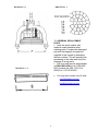
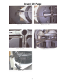
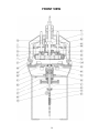
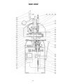
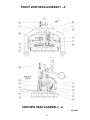
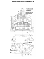
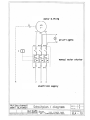
• The adjusting screw (S037)
determines how far the knives will
travel.
• This is accomplished by limiting
the travel of the pressure lever (S030).
• The clearance between the knives
in their “down” position and the plastic
rounding plate should be the thickness
of a sheet of paper.
• If the knives touch the rounding
plate, first make sure that no dirt or old
dough sits between the plastic plate
and the metal rounding “table”.
• If it is clean, remove the dough
entrapment ring (see paragraph # 15).
• Place a sheet of paper on top of the
plate (parchment paper or newspaper).
• (a)Bring down the head of the
machine, and release the knives.
• (b)Pull gently on the paper, you
should be able to pull it out without
tearing.
• (c)If you tear the paper, or are
unable to pull it out, you have to raise
the blades, to do this:
• (d)Release the locknut on the
adjustment screw (S037), that stops
the handle on the way down.
• Turn the screw counterclockwise
one full turn, then repeat steps (a-b-cd) until the paper slides out.
• Fasten the locknut on the
adjustment screw (S037) clockwise.
• Install dough entrapment ring.
12. ADJUSTMENT OF THE V BELTS
• In time, the V belts located in the
base of the machine will wear and
stretch.
• To adjust them, loosen the motor
bolts, move the motor on its railing until
the belts are tight, (see paragraph #
13) tighten the bolts again.
13. REPLACEMENT OF THE V BELTS.
• Disconnect electrical power from
the machine.
Remove the left side cover from the
machine base.
• Release spring (S054) completely,
and disconnect from the frame.
• Tap out beveled pin (S061) from
the bottom up, and remove.
• Pull and turn lever (S050), until
assembly S050/58 is free.
• Loosen the 4 bolts that hold the
motor (S071) to the motor mounts
(S092), and slide the motor until the 3
V belts (S070) are loose.
• Remove the old V belts one at a
time, and replace with new ones.
• Slide the motor until the 3 new V
belts are tight; when pushing against
the new belts with your finger you
should get a ¼” deflection, if you get
less, damage to the motor bearings will
be the result, if you have too much
play, the belts will slip.
• Re-tighten the 4 bolts that hold the
motor to the machine frame.
• Push and turn lever S050 and
insert assembly S058/50.
• Insert beveled pin S061 from the
top into the assembly S058/50, and
tap gently until fully seated, do not
force pin or rivet it, just tap gently.
• Insert spring S054 and tighten until
the lever S050 moves freely to it’s
resting position.
• Install the left side cover on the
base of the machine.
• Re-connect the electrical power.
•
12.
15. REMOVING THE DOUGH
ENTRAPMENT RING (S007)
• Pull down the pressing lever
(S030), keep it down by holding it
under your armpit, and now grab the
dough entrapment ring with hands, one
in the front and one in the back.
• Turn the ring clockwise until the
slots on the top of the ring line up with
the holding brackets (S081); now
release the pressing lever to the “up”
position.
• The ring can now be removed from
the machine.
ADJUSTMENT OF THE KNIVES
7