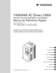
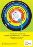
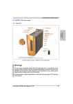
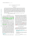
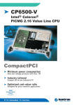
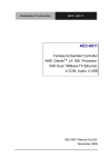
1
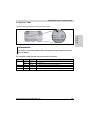
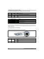
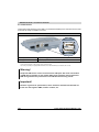
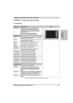
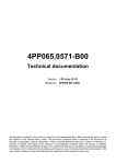
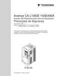
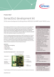
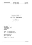
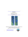
4PP065.0571-X74F • Order data
9. 4PP065.0571-X74F
9.1 Order data
Model number
Short description
4PP065.0571-X74F
Power Panel PP65, 5.7" QVGA color TFT display with touch
screen (resistive), 10 function keys, 10 MB DRAM, 232 kB SRAM,
CompactFlash slot, Ethernet 10/100, 1x X2X Link, 2x USB, IP65
protection (front side).
Order application memory separately.
Order TB103 and TB704 terminal blocks separately.
Image
Required accessories
0TB103.9
Connector, 24 VDC, 3-pin female, screw clamp, 3.31 mm², protected against vibration by the screw flange
0TB103.91
Connector, 24 VDC, 3-pin female, cage clamp, 3.31 mm², protected against vibration by the screw flange
0TB704.9
Accessory terminal block, 4-pin, screw clamp, 1.5 mm²
0TB704.91
Accessory terminal block, 4-pin, cage clamp, 2.5 mm²
5CFCRD.0064-03
CompactFlash 64 MB Western Digital
5CFCRD.0128-03
CompactFlash 128 MB Western Digital
5CFCRD.0256-03
CompactFlash 256 MB Western Digital
5CFCRD.0512-03
CompactFlash 512 MB Western Digital
5CFCRD.1024-03
CompactFlash 1 GB Western Digital
5CFCRD.2048-03
CompactFlash 2 GB Western Digital
5CFCRD.4096-03
CompactFlash 4 GB Western Digital
5CFCRD.8192-03
CompactFlash 8 GB Western Digital
5CFCRD.0512-04
CompactFlash 512 MB B&R
5CFCRD.1024-04
CompactFlash 1 GB B&R
5CFCRD.2048-04
CompactFlash 2 GB B&R
5CFCRD.4096-04
CompactFlash 4 GB B&R
5CFCRD.8192-04
CompactFlash 8 GB B&R
5CFCRD.016G-04
CompactFlash 16 GB B&R
Table 79: 4PP065.0571-X74F - Order data
96
Power Panel 65 User's Manual V 1.00
4PP065.0571-X74F • Technical data
Model number
Short description
Image
Optional accessories
0AC201.91
Lithium batteries, 4 pcs., 3 V / 950 mAh, button cell
4A0006.00-000
Lithium battery 3 V / 950 mAh, button cell
5 DIN A4 legend sheets, 16 strips for a total of 40 PP65 5.7" devices, CorelDraw template is available online for download.
4PP065.IF10-1
PP65 interface module, 1 RS232 interface
4PP065.IF23-1
PP65 interface module, 1 RS232/RS485/RS422 interface (RS422: electrically isolated, RS485: electrically isolated and
network-capable), 1 CAN interface (electrically isolated and network-capable).
Order 0TB710.91 terminal blocks separately.
4PP065.IF24-1
PP65 interface module, 1 PROFIBUS DP slave interface (electrically isolated and network-capable), 1 RS232/RS422/
RS485 interface (RS422/RS485: electrically isolated and network-capable)
4PP065.IF33-1
PP65 interface module, 2 CAN interfaces (electrically isolated and network-capable).
Order 0TB710.91 terminal blocks separately.
5MMUSB.2048-01
USB 2.0 flash drive 2048 MB B&R
Chapter 2
Power Panel 65
4A0075.00-000
Included in delivery
4PP065.0571-X74F
Power Panel 65 including installation accessories
4A0006.00-000
Lithium battery 3 V / 950 mAh, button cell
Table 79: 4PP065.0571-X74F - Order data (cont.)
9.2 Technical data
Product ID
4PP065.0571-X74F
General information
B&R ID code
$B9BC
LEDs
CF (CompactFlash)
Status
X2X
User
4
Orange
Red/green
Orange
Green
Battery
Type
Method
Service life
Removable
Renata 950 mAh
Lithium Ion
4 years 1)
Yes, accessible from the outside
Backup capacitor
Buffer time
10 min.
Certification
c-UL-us
CE
GOST-R
Yes
Yes
Yes
Table 80: 4PP065.0571-X74F - Technical data
Power Panel 65 User's Manual V 1.00
97
4PP065.0571-X74F • Technical data
Product ID
4PP065.0571-X74F
Controller
Boot loader, operating system
PP65 supported beginning with version
Processor
Type
Clock frequency
L1 cache
L2 cache
Expanded command set
Floating point unit (FPU)
Flash
Cooling
Mode/Node switches
Remanent variables
Watchdog
Automation Runtime
C2.96
Geode LX800, 32-bit x86
500 MHz
128 kB (64 kB I-Cache / 64 kB D-Cache)
128 kB
MMX technology, 3D Now
Yes
4 MB (for firmware)
Passive via heat sink
2, 16 digits each
32 kB
MTCX 2)
Real-time clock
Accuracy
Battery-buffered
At 25°C: Typ. 30 ppm (2.5 seconds) per day3)
Yes
Power failure logic
Controller
Buffer time
MTCX 2)
10 ms
Graphics
Controller
Memory
Standard memory
RAM
User RAM
PP65 Compact IF slot
Geode LX800
8 MB shared memory (reserved in application memory)
128 MB DDR SDRAM
200 kB SRAM
1
Interfaces
CompactFlash slot 1
Amount
Type
Design
USB
Amount
Type
Design
Transfer rate
Current load
Ethernet
Amount
Design
Controller
Transfer rate
Max. transfer rate
Cables
Status LEDs
1
Type I
Primary IDE device
2
USB 1.1, USB 2.0
Type A
Low speed (1.5 Mbit/s), full speed (12 Mbit/s), to high speed (480 Mbit/s)
Max. 500 mA per connection
1
Shielded RJ45 port (10/100 Base-T)
Intel 82551ER
10/100 Mbit/s
100 Mbit/s
S/STP (Category 5)
Link/Activity
Table 80: 4PP065.0571-X74F - Technical data
98
Power Panel 65 User's Manual V 1.00
4PP065.0571-X74F • Technical data
Product ID
4PP065.0571-X74F
X2X
Amount
Type
Design
Number of stations
Distance between stations
Network topology
Internal bus supply
Bus termination resistor
1
X2X Link master
4-pin multipoint plug
Max. 253
Max. 100 m
Line
No
Internal
Type
Color TFT
Diagonal
5.7" (144 mm)
Colors
262,144
Resolution
QVGA, 320 x 240 pixels
Contrast
350:1
Viewing angle
Horizontal
Vertical
Direction R / direction L = 60°
Direction U = 65° / direction D = 50°
Backlight
Brightness
Half-brightness time
500 cd/m²
50,000 h
Touch screen
Technology
Controller
Degree of transmission
Screen rotation
Chapter 2
Power Panel 65
Display
Analog, resistive
B&R, 12-bit
70% ±10%
Yes (see Chapter 4 "Commissioning", section "Screen rotation" on page 131)
Keys
Design
Membrane keypad with metallic snap-action disks
Total keys
10 membrane keys
Function keys
10 (labeled with legend strips)
System keys
-
Electrical characteristics
Rated voltage
24 VDC ±25%
Rated current
0.45 A
Starting current
Max. 2.8 A
Power consumption
Typ. 10 W
Electrical isolation
No
Operating conditions
EN 60529 protection
IP20 back side (only with installed CompactFlash card)
IP65 / NEMA 250 type 4X, dust and sprayed water protection (front side)
Table 80: 4PP065.0571-X74F - Technical data
Power Panel 65 User's Manual V 1.00
99
4PP065.0571-X74F • Supported interface modules
Product ID
4PP065.0571-X74F
Environmental conditions
Temperature
Operation
Storage
Transport
0 to 50°C
-20 to 70°C
-20 to 70°C
Relative humidity
Operation
Storage
10 to 90%, non-condensing
T ≤ 40°C: 5 to 90%, non-condensing
T > 40°C: < 90%, non-condensing
Vibration
Operation (continuous)
Operation (occasional)
Storage
Transport
2 to 9 Hz: 1.75 mm amplitude / 9 to 200 Hz: 0.5 g
2 to 9 Hz: 3.5 mm amplitude / 9 to 200 Hz: 1 g
2 to 8 Hz: 7.5 mm amplitude / 8 to 200 Hz: 2 g / 200 to 500 Hz: 4 g
2 to 8 Hz: 7.5 mm amplitude / 8 to 200 Hz: 2 g / 200 to 500 Hz: 4 g
Shock
Operation
Storage
Transport
15 g, 11 ms
30 g, 15 ms
30 g, 15 ms
Installation at altitudes above sea level
Max. 3000 m
Mechanical characteristics
Housing
Polyester
Front
Multi-layer membrane with insertion slots for key labels
Outer dimensions
Width
Height
Depth
203 mm
145 mm
56.5 mm
Weight 4)
0.75 kg
Table 80: 4PP065.0571-X74F - Technical data
1) Typical service life (at 50% buffer operation: 25°C when device turned off, 50°C when device turned on)
Maximum service life in 24-hour operation (no buffer): 6 years at 25°C, 5 years at 50°C
Maximum service life when device turned off: 2 years at 25°C, 1 year at 50°C
2) Maintenance Controller Extended
3) At max. specified ambient temperature: Typ. 50 ppm (4 s), worst case 100 ppm (8 s)
4) Weight including fasteners and battery (46.5 g) but without an interface module
9.3 Supported interface modules
Interface modules are supported beginning with the following Automation Runtime versions:
Interface modules
Automation Runtime version
4PP065.IF10-1
4PP065.IF23-1
4PP065.IF24-1
4PP065.IF33-1
C2.96
C2.96
A3.07
C2.96
Table 81: 4PP065.0571-X74F - Supported interface modules
100
Power Panel 65 User's Manual V 1.00
4PP065.0571-X74F • Diagnostic LEDs
9.4 Diagnostic LEDs
Chapter 2
Power Panel 65
There are four diagnostic LEDs on the back of the PP65:
Figure 26: 4PP065.0571-X74F - Diagnostic LEDs
Information:
The behavior of the status LED has been changed beginning with AR versions J2.96,
E3.01 and B3.06.
9.4.1 Diagnostic LEDs until AR versions I2.96, D3.01 and A3.06
LED
Color
Status
Description
Status
Red
On
Error / Reset
Orange
On
Boot / Ready mode
User
Green
On / Off
This LED can be operated by the user (with the AsHW library).
X2X
Orange
On
The module is sending data via the X2X Link interface.
CF
Orange
On
CompactFlash card being accessed
Table 82: 4PP065.0571-X74F - Diagnostic LEDs until AR versions I2.96, D3.01 and A3.06
Power Panel 65 User's Manual V 1.00
101
4PP065.0571-X74F • Diagnostic LEDs
9.4.2 Diagnostic LEDs beginning with AR versions J2.96, E3.01, B3.06
LED
Color
Status
See Table 84 "4PP065.0571-X74F - Status LED blink codes".
Status
Description
User
Green
On / Off
This LED can be operated by the user (with the AsHW library).
X2X
Orange
On
The module is sending data via the X2X Link interface.
CF
Orange
On
CompactFlash card being accessed
Table 83: 4PP065.0571-X74F - Diagnostic LEDs beginning with AR versions J2.96, E3.01, B3.06
Blink code (200 ms grid)
Meaning
Error / Reset
No error, normal operation
No battery or battery capacity low
No CompactFlash
Reserved for future blink codes
Table 84: 4PP065.0571-X74F - Status LED blink codes
Since only one error can be indicated by a blink code, more important errors are assigned a higher priority. Fatal errors, for example, have a much higher priority than unimportant errors (e.g.
battery capacity low).
9.4.3 ACT/LNK LEDs for the RJ45 ports
There are two additional LEDs next to the Ethernet interface:
LNK
(green)
ACT
(orange)
Figure 27: 4PP065.0571-X74F - Ethernet LEDs
LED
Color
Status
Description
ACT
Orange
On
No Ethernet activity on bus
Blinking
Ethernet activity on the bus
On
A link to the remote station has been established.
LNK
Green
Table 85: 4PP065.0571-X74F - ACT/LNK LEDs for the RJ45 ports
102
Power Panel 65 User's Manual V 1.00
4PP065.0571-X74F • Connection elements
9.5 Connection elements
Chapter 2
Power Panel 65
Supply voltage
Ethernet interface
USB interfaces
X2X Link interface
Figure 28: 4PP065.0571-X74F - Connection elements
9.5.1 X2X Link interface
Pin assignments
Application interface
X2X Link
Terminal
1
X2X
X2X
X2X ⊥
X2X \
SHLD
Interface
2
X2X⊥
X2X ground
3
X2X\
X2X data inverted
4
SHLD
Shield
1
2
3
4
X2X Link
X2X data
Required accessories
0TB704.9
Accessory terminal block, 4-pin, screw clamp, 1.5 mm²
0TB704.91
Accessory terminal block, 4-pin, cage clamp, 2.5 mm²
4-pin multipoint plug
Table 86: 4PP065.0571-X74F - Pin assignments - X2X Link
Power Panel 65 User's Manual V 1.00
103
4PP065.0571-X74F • Connection elements
9.5.2 USB interface
This Power Panel 65 device has a USB 2.0 (Universal Serial Bus) host controller with two USB
ports that are easily accessible to the user.
USB interface
USB Port 1
USB Port 2
Transfer speed 1)
Low speed (1.5 Mbit/s), full speed (12 Mbit/s), to high speed (480 Mbit/s)
Power supply
Max. 500 mA per port 2)
Table 87: 4PP065.0571-X74F - USB ports
1) The actual value depends on the operating system or driver being used.
2) For safety, every USB port is equipped with a maintenance-free "USB current-limiting circuit breaker" (max. 500 mA).
Warning!
Peripheral USB devices can be connected to the USB ports. Due to the vast number
of USB devices available on the market, B&R cannot guarantee their performance.
B&R does guarantee the performance of all USB devices that they provide.
Important!
Because of general PC specifications, these interfaces should be handled with extreme care with regard to EMC, location of cables, etc.
104
Power Panel 65 User's Manual V 1.00
4PP065.0571-X74F • Connection elements
9.5.3 Ethernet interface
Interface
Pin assignments
Ethernet interface
1
RJ45 twisted pair socket
(10BaseT/100BaseT)
1
RXD
Receive signal
2
RXD\
Receive signal inverted
3
TXD
Transmit signal
4
Termination
Termination
5
Termination
Termination
6
TXD\
Transmit signal inverted
7
Termination
Termination
8
Termination
Termination
Chapter 2
Power Panel 65
Terminal
Table 88: 4PP065.0571-X74F - Pin assignments - Ethernet interface
9.5.4 Supply voltage
Pin assignments can be found both in the following table and printed on the back of the Power
Panel. The Power Panel has reverse polarity protection that prevents the supply voltage from
being connected incorrectly, which would damage the device. Overload protection must be provided by an external fuse (5A, fast-acting).
Supply voltage
Pin assignments
Terminal
Assignment
+ 24 VDC
Functional ground
GND
Required accessories
0TB103.9
Connector, 24 VDC, 3-pin female, screw clamp, 3.31 mm², protected
against vibration by the screw flange
0TB103.91
Connector, 24 VDC, 3-pin female, cage clamp, 3.31 mm², protected
against vibration by the screw flange
3-pin multipoint plug
Table 89: 4PP065.0571-X74F - Pin assignments - Supply voltage
Important!
The pin's connection to the functional ground should be as short as possible (e.g.
in the control cabinet). We recommend using the largest possible conductor crosssection on the supply plug.
Power Panel 65 User's Manual V 1.00
105
4PP065.0571-X74F • Operating mode and node number switches
9.6 Operating mode and node number switches
Figure 29: 4PP065.0571-X74F - Operating mode and node number switches
The Power Panel 65 is equipped with 2 hex switches that are used for the operating mode or
node number of the device. Switch positions 01 - FE are used to set the INA station number for
the Ethernet interface.
Switch position
Description
00
Reserved
01 - FE
INA node number of the Ethernet interface
FF
Diagnostic mode:
The CPU boots in diagnostic mode. Program sections in User RAM and User FlashPROM are not initialized.
After diagnostic mode, the CPU always boots with a cold restart.
Table 90: 4PP065.0571-X74F - Operating mode and node number switches
106
Power Panel 65 User's Manual V 1.00
4PP065.0571-X74F • Dimensions
Chapter 2
Power Panel 65
137.2
9.7 Dimensions
109.5
8
194
9
5.5
9
39.25
137
145
8
203
27.3
51
Figure 30: 4PP065.0571-X74F - Dimensions
Installation cutout: 188 ±0.5 mm x 130 ±0.5 mm
Power Panel 65 User's Manual V 1.00
107
4PP065.0571-X74F • Dimensions
108
Power Panel 65 User's Manual V 1.00