Download Power Panel 300/400
Transcript
Technical Data • Power Panel 400 with Automation Runtime
4.9 Device 4PP420.1043-75
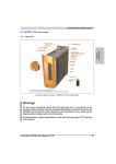
Figure 128: Front view - 4PP420.1043-75
aPCI Slot 1
Battery compartment
Grounding clip
Power button
CompactFlash slot
(with latch)
Reset button
Supply
voltage
SW2
(x1)
SW1
(x16)
USB
Ethernet
COM
Status
LEDs
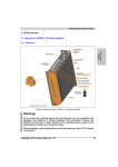
Figure 129: Rear view - 4PP420.1043-75
196
Power Panel 300/400 User's Manual V 1.60
Technical Data • Power Panel 400 with Automation Runtime
4.9.1 Technical data
Features
4PP420.1043-75
Boot loader / Operating system
Automation Runtime
Processor
Type
Expanded command set
L1 cache
L2 cache
Floating point unit (FPU)
Cooling
Method
Chapter 2
Technical Data
Geode LX800 500 MHz, 32-bit x86
MMX technology, 3D Now
128 KB (64 KB L cache / 64 KB D cache)
128 KB
Yes
Passive (heat sink)
Flash
2 MB (for firmware)
Memory
Type
Quantity
DDR SDRAM
128 MB (64 MB < Rev. D0)
Graphics
Controller
Memory
Geode LX800
8 MB shared memory (reserved by main memory)
SRAM
Quantity
Battery-buffered
512 KB
Yes
Watchdog
Controller
MTCX1)
Power failure logic
Controller
Buffer time
MTCX1)
10 ms
Real-time clock (RTC)
Battery-buffered
Accuracy
Yes
At 25°C: typically 30 ppm (2.5 seconds) 2) per day
Battery
Type
Removable
Lifespan
Backup capacitor (for changing battery)
Buffer time
Renata 950 mAh
Yes, accessible from the outside
3 years 3)
10 minutes
Ethernet
Controller
Transfer rate
Connection
Cables
NE2000-compatible
Intel 82551ER
10/100 Mbps
RJ45 twisted pair (10 Base T / 100 Base T)
S/STP (category 5)
-
CompactFlash
Type
Amount
Connection
Type I
1 slot
Primary IDE device
Serial interface COM
Type
UART
Transfer rate
Connection
RS232, modem-capable, not electrically isolated
16C550 compatible, 16-byte FIFO
Max. 115 kBaud
9-pin DSUB
Table 72: Technical data - 4PP420.1043-75
Power Panel 300/400 User's Manual V 1.60
197
Technical Data • Power Panel 400 with Automation Runtime
Features
USB interface
Type
Amount
Transfer rate
Connection
Current load
4PP420.1043-75
USB 1.1, USB 2.04)
2
Low speed (1.5 MBit/s), full speed (12 MBit/s), to high speed (480 Mbit/s)4)
Type A
Max. 500 mA per connection
Reset button
Yes, accessible from the outside
Power button
Yes, accessible from the outside
LEDs
Mode / Node switch
aPCI slots
Display
Type
Diagonal
Colors
Resolution
Contrast
Viewing angle (see page 488)
Horizontal
Vertical
Background lighting
Brightness
Half-brightness time
Screen rotation
Touch screen
Technology
Controller
Degree of transmission
1x CF (yellow)
1x combined power (red/green) and user (yellow)
2, 16 digits each
1 (see B&R System 2005 manual for available aPCI interface modules)
TFT colors
10.4 in (264 mm)
262144 colors
VGA, 640 x 480 pixels
600:1
Direction R / direction L =70°
Direction U = 45°/ direction D = 35°
450 cd/m²
55000 hours
Yes, see chapter 3 "Commissioning", section "Screen rotation" on page 361
Analog, resistive
Elo, serial, 12- bit
Up to 80% r 5%
Filter glass
Degree of transmission
Coating
-
Keys/LED
Function keys
Soft keys
Cursor keys
Number block
Other keys
Key lifespan
LED brightness
-
Electrical characteristics
Power supply
Rated voltage
Rated current
Starting current
Power consumption
Electrical isolation
Bleeder resistance
18 - 30 VDC
0.71 A
Maximum 2.8 A
Typically 17 W
Yes
0 Ohm
Table 72: Technical data - 4PP420.1043-75 (Forts.)
198
Power Panel 300/400 User's Manual V 1.60
Technical Data • Power Panel 400 with Automation Runtime
Mechanical characteristics
4PP420.1043-75
Outer dimensions
Width
Height
Depth
323 mm
260 mm
86 mm
Front
Frame
Design
Membrane
Dark gray border around display
Light background
Gasket
Housing
Metal
Weight
Approx. 3.9 kg (without aPCI interface modules)
Chapter 2
Technical Data
Aluminum, naturally anodized5)
Gray5)
Polyester
Similar to Pantone 432CV5)
Similar to Pantone 427CV5)
Flat gasket around display front
Environmental characteristics
Ambient temperature
Operation
Storage
Transport
Relative humidity
Vibration
Operation (continuous)
Operation (occasional)
Storage
Transport
0 .. +50°C
-20 .. +70°C
-20 .. +70°C
See 4.9.2 "Temperature humidity diagram" on page 200
2 - 9 Hz: 1.75 mm amplitude / 9 - 200 Hz: 0.5 g
2 - 9 Hz: 3.5 mm amplitude / 9 - 200 Hz: 1 g
2 - 8 Hz: 7.5 mm amplitude / 8 - 200 Hz: 2 g / 200 - 500 Hz: 4 g
2 - 8 Hz: 7.5 mm amplitude / 8 - 200 Hz: 2 g / 200 - 500 Hz: 4 g
Shock
Operation
Storage
Transport
Protection type
15 g, 11 ms
30 g, 15 ms
30 g, 15 ms
IP20 back side (only with installed CompactFlash card, inserted aPCI module
or with an optional aPCI cover)
IP65 / NEMA 250 type 4X, dust and sprayed water protection (front side)
Altitude
Max. 3000 m
Table 72: Technical data - 4PP420.1043-75 (Forts.)
1) Maintenance Controller Extended.
2) At max. specified ambient temperature: typ. 50 ppm (4 seconds) - worst-case 100 ppm (8 seconds).
3) Typical lifespan (at 50% buffer operation, temperature 25°C when off, 50°C when on).
Maximum lifespan in 24-hour operation (no buffer) 6 years at 25°C or 5 years at 50°C.
Maximum lifespan switched off: 2 years at 25°C or 1 year at 50°C.
4) The actual value depends on the operating system or diver being used.
5) Depending on the process or batch, there may be visible deviations in the color and surface structure.
Power Panel 300/400 User's Manual V 1.60
199
Technical Data • Power Panel 400 with Automation Runtime
100
95
90
85
80
75
70
65
60
55
50
45
40
35
30
25
20
15
10
5
0
Storage
Relative humidity [%RH] (non-condensing)
4.9.2 Temperature humidity diagram
-80
-70
-60
-50
-40
-30
Operation
-20
-10
10
20
-
Temperature [°C]
0
+
30
40
50
60
70
80
90
Figure 130: Temperature humidity diagram - 4PP420.1043-75
4.9.3 Dimensions
9.9
2.9
11.5
300
81.5
240
± 0.1 mm
± 0.2 mm
± 0.3 mm
± 0.5 mm
± 0.8 mm
up to 6 mm
over 6 to 30 mm
over 30 to 120 mm
over 120 to 400 mm
over 400 to 1000 mm
10
100
260
Nominal measurement General tolerance from
range
DIN ISO 2768 medium
8
75
3
27
323
27.5
Figure 131: Dimensions - 4PP420.1043-75
200
Power Panel 300/400 User's Manual V 1.60
Technical Data • Power Panel 400 with Automation Runtime
4.9.4 Cutout installation
The cutout hole is to be made according to the following dimensions for cutout installation. The
device must be mounted using the retaining clips included in delivery.
Outer contour (Power Panel)
260
251.5
Chapter 2
Technical Data
Cutout
Cutout dimensions 303 mm ± 0.5 mm x 243 mm ± 0.5 mm for
4PP320.1043-31
4PP420.1043-75
4PP420.1043-B5
4PP480.1043-75
5PP320.1043-39
8.5
323
313
10
0
0
Figure 132: Cutout installation - 4PP420.1043-75
4.9.5 Contents of delivery
The following components are included in the delivery of the Power Panel device:
Amount
Component
1
Power Panel PP420 10.4" VGA, 1 aPCI, touch screen
6
Retaining clips included
1
Lithium battery 3 V / 950 mAh included
Table 73: Contents of delivery - 4PP420.1043-75
Power Panel 300/400 User's Manual V 1.60
201


