1
EZ-SCREEN LP
Instruction Manual
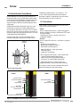
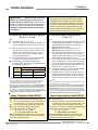
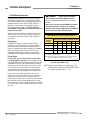
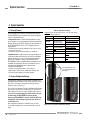
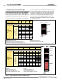
a. Two pairs
in a horizontal
plane
Installation and Overview
Alignment
3.2 Mechanical Mounting Procedure
Emitter
Receiver
Once the mechanical layout considerations of Section 3.1 are
addressed, mount the sensors and route the cables.
Receiver
Emitter
3.2.1 Sensor Mounting
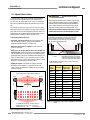
Emitter/receiver pairs may be spaced from 0.1 m to 7 m (4" to
23') apart. This distance is reduced if corner mirrors are used
(see Section 3.1.7).
Scan Code 1
Scan Code 1
Receiver 1
Emitter 1
Scan
Code 1
b. T wo or three pairs stacked
(or alternate receiver/
emitter positions)
Receiver 2
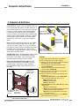
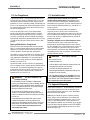
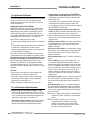
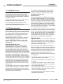
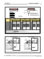
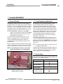
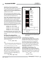
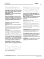
Each sensor is shipped with two end-cap brackets and at
least two side-mount brackets. The supplied end-cap brackets
allow 360° rotation. Side-mount brackets allow 30° rotation
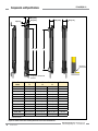
in one direction, and 10° in the other (see Figure 3-10). Sidemount brackets may be mounted on either or both sides of the
housing. If additional rotation is required, see the accessory
brackets in Section 2.4.
Center-mounted side brackets must be used with longer
sensors, if they are subject to shock or vibration. In such
situations, the sensors are designed to be mounted with up to
690 mm unsupported distance (between brackets). Sensors
830 mm and longer are supplied with one or more additional
side brackets for center-mounting (see Figure 3-10).
Emitter 2
Scan
Code 2
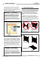
Mounting the End-Cap Brackets
Emitter 3
Receiver 3
Scan
Code 2
c. T wo pairs at right angles
Scan Code 1
Receiver
Emitter
Scan Code 2
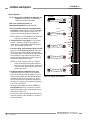
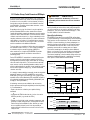
1. From a common point of reference (ensuring the minimum
separation distance calculated in Section 3.1.1), measure
to locate the emitter and receiver in the same plane, with
their midpoints directly opposite each other. Important: The
connector ends of both sensors must point in the same
direction (see Figure 3-5 and warning, Section 3.1.4).
Loosely mount the brackets to the desired surface, using
the supplied M5 bolts and nuts, or user-supplied hardware.
Brackets may face “in” or “out,” as desired (see Figure 2-6).
2. Attach the end-cap bracket plate to each end of the sensor,
using the supplied M3x6 screws.
d. Multiple pairs
in a horizontal plane
Horizontal
Emitter
Horizontal
Receiver
Opaque Shield
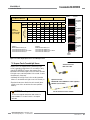
Example shows 2 methods: either alternate scan codes
or insert an opaque shield when multiple
pairs face the same direction
Receiver 1
Receiver 2
Emitter 2
Emitter 3
Receiver 3
Emitter 1
Scan Code 1
Scan Code 2
Scan Code 2
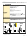
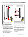
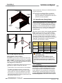
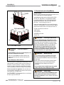
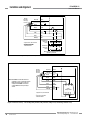
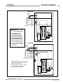
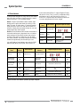
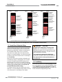
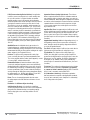
3. Position the emitter and receiver in their brackets, as shown
in Figure 3-11. Loosely attach the front bracket plate to the
bracket, at each end.
4. Verify that the sensor windows directly face each other.
Measure from a reference plane (e.g., a level building floor)
to the same point(s) on the emitter and receiver to verify
their mechanical alignment. Use a carpenter’s level, a
plumb bob, or the optional LAT-1 Laser Alignment Tool (see
Section 2.5) or check the diagonal distances between the
sensors, to achieve mechanical alignment; see Figure 3-11.
Final alignment procedures are explained in Section 3.4.
5. Tighten all fasteners.
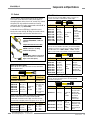
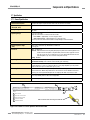
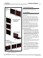
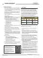
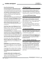
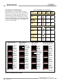
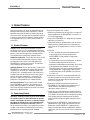
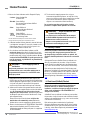
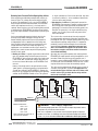
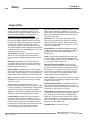
Figure 3-9. Installation of multiple pairs; alternate emitters and
receivers to avoid optical crosstalk.
Banner Engineering Corp. • Minneapolis, U.S.A.
www.bannerengineering.com • Tel: 763.544.3164
P/N 140044
P/N 133487
rev. A 27