1
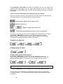
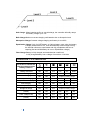
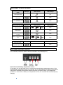
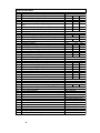
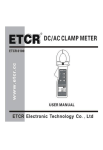
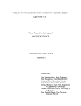
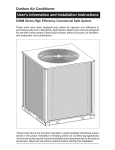
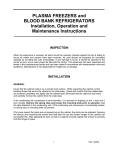
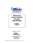
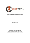
Solar Controller / Battery Charger
Input: DC12V Solar panel (Max. 25V)
Output: DC12V 10A / DC12V 15A
Model Number: ZS-10A / ZS-15A
User’s Manual
1
FEATURE
●Advanced MCU control pulse width modulated (PWM) technology, high efficiency
operation.
●Target for Gel, AGM, Conventional lead-acid (WET) and Calcium Batteries.
●Built in regulator to prevent your battery from being overcharged. Overcharging
occurs when the charge voltage is unregulated. This can result in premature battery
failure.
●Come with regulator to prevent your battery from being under charged, in the solar
energy field, battery undercharge always occurs, especially on some Conventional
lead –acid or Calcium batteries; The unit provides an automatic Equalization feature
for deeply drained Conventional lead acid battery or Calcium battery, as well as
provides a cycling automatic Equalizing feature every 28 days.
●Can be connected to the battery permanently to keep the battery fully charged by
using a process called “floating”. This means the controller will stop charging when
the battery is full and will automatically start charging the battery as required. This
process will also reduce water loss and help prevent the battery from ‘drying out’.
●Protects your battery from discharge at night. Under low light or no light conditions
the solar panel voltage could be less than the battery voltage. The unit contains a
special circuit which prevents current flowing back from the battery and into the
solar panel.
●Colored LED’s to easily indicate the operational status and battery conditions.
●Digital LCD to directly display battery voltage, charging current, charging capacity
(Amp hour), battery types, full charge and faulty codes.
●Provides external battery temperature sensor (Optional).
●Multi charging protections against reverse polarity, short circuit, over temperature,
over voltage, etc.
●Surface Mount or Flush Panel Mount options.
●Conformal-coating circuit boards and plated terminals apply to hostile environments.
●Waterproof and non-waterproof selectable.
For use with 12Volt Solar Panel Only
Suitable for Solar panels up to 170 / 255 Watts for ZS-10A / ZS-15A
2
WARNING – IMPORTANT PLEASE READ
● This charger is designed for indoor use (non-waterproof type ) or outdoor
Use (waterproof type).
● Do not disassemble the controller. Take to a qualified person if the unit
requires repairing.
● Lead acid batteries can be dangerous. Ensure no sparks or flames are
present when working near batteries.
● Eye protection should always be used. Never short circuit the battery
● Given sufficient light solar panels always generate energy even when they
are disconnected.
● Accidental ‘shorting’ of the terminals or wiring can result in sparks causing
personal injury or a fire hazard. We recommend that you cover up the
panel(s) with some sort of soft cloth so you can block all incoming light
during the installation. This will ensure that no damage is caused to the
Solar Panel or Battery if the wires are accidentally short circuited.
● Always install a battery fuse on each circuit including the solar controller
● Do not reverse connect the wires to the solar panel or battery
MOUNTING THE DEVICE
The Solar Controller is mounted as below
The quickest and easiest way to mount the unit is to use the two plastic
spacers and self tapping screws supplied and mount the unit to a flat surface,
3
WIRING CONNECTIONS
To protect the Battery and the Solar Panel, we strongly recommend that you place a
inline fuse on the positive wire on both the “Solar” and “Battery” Circuits. 20A fuse for
ZS-10A, 30A fuse for ZS-15A (As close to the Battery /Panel as possible)
The Solar Controller has 4 terminals which are clearly marked ‘Solar’ and ‘Battery’.
There is a (12V) and earth (GND) terminal for each circuit.
Refer to the wiring diagram below.
Correct Wire Size:
Please refer to the wire size chart
below to determine the minimum
size wire needed for each
connection. This will also ensure
you get the best performance out
of your solar regulator.
Length of
Wire
Size (AWG)
Battery Connection
Solar Array Connection
< 0.9m
6m
9m
18 or 16
14
12
12m
12
1. Using the stranded wires, screw tightly the wires to the “Solar” terminal on the back
of controller and connect to the Solar Panel like shown.
2. Using the stranded wires, screw tightly the wires to the “Battery” terminal on the
back of controller and connect to the Battery like shown.
When the connections are completed, the Solar Controller will start working
automatically.
OPERATION - LCD DISPLAY
Please check your battery manufacturer’s specifications to select correct battery type.
The unit provides 4 battery types for selections: Gel, AGM, WET (conventional lead
acid), and Calcium.
4
Press BATTERY TYPE button and hold for 3 seconds to go into your battery type
selection mode, the battery type you select will be shown on the LCD meter, the
default setting is AGM Battery; the controller will automatically memorize your battery
type setting.
Caution: Incorrect battery type setting may damage your battery.
When the controller powers on, the unit will run self-qualify mode and automatically
show below items on LCD before going into charging process
Self-test starts, digital meter segments test
Software version test
Rated voltage and current test
External battery temperature sensor test (if connected)
After going into charging process, the LCD displays the charging statues as below:
Press VOLT / AMP button in sequence, the LCD will display in turn with
Battery Voltage, Charging Current, Charged capacity (Amp-hour) and Battery
Temperature (if external temperature sensor connected)
Display in the day time-
Display during the night-
Display when battery fully charged
Press VOLT / AMP button in sequence, the LCD will display in turn with
Battery Voltage, Charging Current, if you do not press the button, the LCD will
alternatively display the FUL and VOLT or FUL and AMP every 2 seconds
or
CHARGING STAGES
The VOLT / AMP button can be changed at any time during charging process.
The LCD also can be treated as an independent voltage meter or thermometer.
A voltage less than 11.5V Volts indicates that the battery is discharged and needs
re-charging.
.
5
Soft Charge- When batteries suffer an over-discharge, the controller will softly ramps
the battery voltage up to 10V.
Bulk Charge-Maximum current charging until batteries rise to Absorption level
Absorption Charge-Constant voltage charging and battery is over 85%.
Equalization Charge*-Only for WET battery or Calcium battery type, when the battery
is deeply drained below 10V, it will automatically run this stage to bring
the internal cells as an equal states and fully complement the loss of
capacity.(Gel and AGM battery do not run Equalization charge)
Float Charge-Battery is fully charged and maintained at a safe level.
A fully charged battery has a voltage of more than 13.6 Volts.
OPERATION - L.E.D. INDICATION
The 6 LED’s indicate the
charging status and the
battery condition
Red
Blue
Green
Green
Yellow
Red
ON
OFF
OFF
OFF
OFF
Flash
ON
Flash
OFF
OFF
OFF
ON
Bulk charging
ON
ON
OFF
Subject to battery voltage
Absorption charging
ON
ON
OFF
ON
OFF
OFF
Equalization charging
ON
ON
OFF
ON
OFF
OFF
Float charging
ON
OFF
ON
OFF
OFF
OFF
Solar panel weak
Flash
OFF
OFF
Subject to battery voltage
At night no charge
OFF
OFF
OFF
Subject to battery voltage
ON
ON
OFF
OFF
OFF
ON
ON
ON
OFF
OFF
ON
OFF
ON
ON
OFF
ON
OFF
OFF
Solar Power Present-No
battery connected
Soft charging
Battery Voltage below 11.5V
(+/-0.2V)
Battery Voltage between
11.5V - 12.5V(+/-0.2V)
Battery Voltage above 12.5V
(+/-0.2V)
.
6
.
ABNORMAL OPERATION MODE
Solar panel abnormal
mode
LCD display
LED indication
Solar panel weak
ON
Flash
Solar panel reverse
connection
Flash
Solar panel over voltage
(> 26.5V)
Flash
Battery abnormal mode LCD display
Battery disconnected or
less than 3.0V
Flash
Flash
Flash
Battery over voltage than
> 17.5V
Flash
Battery temperature over
65C
Flash
LCD display
Flash
Flash
LED indication
Battery reverse
connection
The solar controller
abnormal mode
LCD backlight
Flash
LED indication
LCD backlight
Flash
Flash
Flash
Flash
Flash
Flash
LCD backlight
The controller over
temperature protection
.
Flash
OPTIONAL EXTERNAL DEVICE
The controller provides an optional devices (excludes in the packaging box).
Optional external Battery temperature sensor:
As an option, the unit provides a port to connect the external battery temperature sensor; If the
external battery temperature sensor is connected, the unit will optimize the charging performance
subjected to the battery temperature detected and also provide the battery over temperature
protection, in some case, if battery over temperature occurs, the controller will automatically stop
charging.
7
SPECIFICATIONS
1
1-1
1-2
1-3
1-4
1-5
Electrical Parameters
Rated solar panel amps for ZS-15A
Rated solar panel amps for ZS-10A
Normal input Solar cell array voltage
Max. solar cell array voltage (output has no load)
1-6
1-7
2
2-1
2-2
2-3
2-4
2-5
Standby current consumption at night
Maximum voltage drop-Solar panel to battery
Charging characteristics
Minimum battery start charging voltage
Soft start charging voltage
Soft start charging current (50% PWM duty)
Bulk charge voltage
Absorption charging voltage at 25*C
--Gel type battery
--AGM type battery (default setting)
--WET type battery
--Calcium type battery
Absorption transits to Equalizing or Float condition:
--Charging current drops to
-- or Absorption charging timer timed out
Equalization charging active
--Only for WET or Calcium battery
--Battery voltage discharged to less than
--Automatic equalizing charging periodical
Equalization charging voltage at 25*C
Equalization charging timer timed out
Float charging voltage at 25*C
Voltage control accuracy
Battery temperature compensation coefficient
Temperature compensation range
Protection
Against reverse polarity or short circuit at panel side
Against reverse polarity or short circuit at battery side
No reverse current from battery to solar at night
Over temperature protection during charging
Transient over voltage protection with TVS or varistor
Electrical parts
Input output terminal
Temperature sensor port (Press and Release type)
Physical Parameters
Controller material
Power terminal maximum stranded wire size
Mounting
IP grade
Net weight
Environmental characteristics
Operating temperature
Storage temperature
Operating Humidity range
2-6
2-7
2-8
2-9
2-10
2-11
2-12
2-13
3
3-1
3-2
3-3
3-4
3-5
4
4-1
4-2
5
5-1
5-2
5-3
5-4
5-5
6
6-1
6-2
6-3
15
10
15-22
25
The controller lowest operating voltage (at solar or battery 8V
side )
8
5
0.25
Max.
Max.
Max.
Min
AMP
AMP
VDC
VDC
VDC
Max
Max.
mA
VDC
3
Min
3-10
+/-0.2
Up to 15
10-14.0 +/-0.2
VDC
VDC
AMP
VDC
14.1
14.4
14.7
14.9
+/-0.2
+/-0.2
+/-0.2
+/-0.2
VDC
VDC
VDC
VDC
0.5
4
+/0.1
AMP
Hour
10
28
15.5
2
13.6
+/- 1%
-24
+/-0.2
VDC
Day
VDC
Hour
VDC
+/-0.2
+/-0.2
-20 ~ +50
mV/*C
*C
65
*C
M4 terminals
DA 250-350 2P
Plastic, Standard ABS
#12 AWG stranded-3 mm2
Vertical wall mounting
IP22 or IP66,
Approx. 250g
-25 ~ 50*C
-40 ~ 85*C
100% no condensation