1
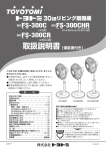
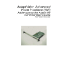
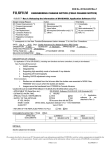
Adept T1 Pendant User’s Guide P/N: 04962-000, Rev A June 2005 3011 Triad Drive • Livermore, CA 94551 • USA • Phone 925.245.3400 • Fax 925.960.0452 Otto-Hahn-Strasse 23 • 44227 Dortmund • Germany • Phone 49.231.75.89.40 • Fax 49.231.75.89.450 41, rue du Saule Trapu • 91300 • Massy • France • Phone 33.1.69.19.16.16 • Fax 33.1.69.32.04.62 The information contained herein is the property of Adept Technology, Inc., and shall not be reproduced in whole or in part without prior written approval of Adept Technology, Inc. The information herein is subject to change without notice and should not be construed as a commitment by Adept Technology, Inc. This manual is periodically reviewed and revised. Adept Technology, Inc., assumes no responsibility for any errors or omissions in this document. Critical evaluation of this manual by the user is welcomed. Your comments assist us in preparation of future documentation. Please email your comments to: [email protected]. Copyright 2005 by Adept Technology, Inc. All rights reserved. The Adept logo, AdeptVision, AIM, HexSight, and HexaVision are registered trademarks of Adept Technology, Inc. ActiveV, Adept, Adept 1060, Adept 1060+, Adept 1850, Adept 1850 XP, Adept 540, Adept 560, Adept C40, Adept C60, Adept CC, Adept Cobra 550, Adept Cobra 550 CleanRoom, Adept Cobra 600, Adept Cobra 800, Adept Cobra i600, Adept Cobra i800, Adept Cobra s600, Adept Cobra s800, Adept DeskTop, Adept Digital Workcell, Adept FFE, Adept FlexFeeder 250, Adept IC, Adept Impulse Feeder, Adept LineVision, Adept MC, Adept MV, Adept MV-10, Adept MV-19, Adept MV4, Adept MV-5, Adept MV-8, Adept NanoBonder EBS, Adept NanoBonder LWS, Adept NanoCell, Adept NanoStage L1P2, Adept NanoStage L3, Adept NanoStage L3P2, Adept OC, Adept SmartAmp, Adept SmartAxis, Adept SmartController CS, Adept SmartController CX, Adept SmartModule, Adept SmartMotion, Adept SmartServo, Adept sDIO, Adept Servo Kit, Adept sMI6, Adept SMIF-EZ, AdeptAlign 650, AdeptAtlas, AdeptCartesian, AdeptForce, AdeptFTP, AdeptGEM, AdeptModules, AdeptMotion, AdeptMotion Servo, AdeptMotion VME, AdeptNet, AdeptNFS, AdeptOne, AdeptOne-MV, AdeptOne-XL, AdeptRAPID, AdeptSix 300, AdeptSix 300CL, AdeptSix 600, AdeptTCP/IP, AdeptThree, AdeptThree-MV, AdeptThree-XL, AdeptTwo, AdeptVicron, AdeptVicron 300S, AdeptVicron 310D, AdeptVision AVI, AdeptVision AGS, AdeptVision GV, AdeptVision I, AdeptVision II, AdeptVision VME, AdeptVision VXL, AdeptVision XGS, AdeptVision XGS II, AdeptWindows, AdeptWindows Controller, AdeptWindows DDE, AdeptWindows Offline Editor, AdeptWindows PC, AIM Command Server, AIM Dispense, AIM PCB, AIM VisionWare, A-Series, AutoCal, AutoTune, AutoWidth, CCM, CCMII, CGM, FlexFeedWare, HyperDrive, Microenvironment, MicroV+, MotionWare, ObjectFinder, ObjectFinder 2000, PackOne, PalletWare, SMIF-C, SMIF-EZX, SMIF-Z, SMIF-ZX, S-Series, UltraOne, V, V+, and VisionTeach are trademarks of Adept Technology, Inc. Any trademarks from other companies used in this publication are the property of those respective companies. Printed in the United States of America Table of Contents 1 Introduction . . . . . . . . . . . . . . . . . . . . . . . . . . . . . . . . . . . . . . . . . . . . . . . . 5 1.1 Product Description . . . . . . . . . . . . . . . . . . . . . . . . . . . . . . . . . . . . . . . . . . . . . . . . 5 1.2 System Compatibility . . . . . . . . . . . . . . . . . . . . . . . . . . . . . . . . . . . . . . . . . . . . . . . 6 1.3 Hardware Specifications . . . . . . . . . . . . . . . . . . . . . . . . . . . . . . . . . . . . . . . . . . . . 6 1.4 Dimensions . . . . . . . . . . . . . . . . . . . . . . . . . . . . . . . . . . . . . . . . . . . . . . . . . . . . . . . 7 1.5 Safety ........................................................... 8 Emergency Stop Switch . . . . . . . . . . . . . . . . . . . . . . . . . . . . . . . . . . . . . . . . . . 8 1.6 How Can I Get Help? . . . . . . . . . . . . . . . . . . . . . . . . . . . . . . . . . . . . . . . . . . . . . . . 9 Related Manuals . . . . . . . . . . . . . . . . . . . . . . . . . . . . . . . . . . . . . . . . . . . . . . . . 9 Adept Document Library . . . . . . . . . . . . . . . . . . . . . . . . . . . . . . . . . . . . . . . . . 9 1.7 Programming the T1 Pendant . . . . . . . . . . . . . . . . . . . . . . . . . . . . . . . . . . . . . . . 10 2 Installation . . . . . . . . . . . . . . . . . . . . . . . . . . . . . . . . . . . . . . . . . . . . . . . . 11 2.1 Installation in a SmartController System . . . . . . . . . . . . . . . . . . . . . . . . . . . . . . 11 Bypass Plugs . . . . . . . . . . . . . . . . . . . . . . . . . . . . . . . . . . . . . . . . . . . . . . . . . . . 12 2.2 Installation in an i-Series Robot System . . . . . . . . . . . . . . . . . . . . . . . . . . . . . . . 13 2.3 Mounting Optional Wall Bracket 3 . . . . . . . . . . . . . . . . . . . . . . . . . . . . . . . . . . . . 14 Identification of Controls and Indicators . . . . . . . . . . . . . . . . . . . . . . . . . . . . . . . . . . . . 15 3.1 Controls and Indicators . . . . . . . . . . . . . . . . . . . . . . . . . . . . . . . . . . . . . . . . . . . . 15 3.2 Enable Switches . . . . . . . . . . . . . . . . . . . . . . . . . . . . . . . . . . . . . . . . . . . . . . . . . . 17 4 Operation . . . . . . . . . . . . . . . . . . . . . . . . . . . . . . . . . . . . . . . . . . . . . . . . . 19 4.1 Main Screen Overview . . . . . . . . . . . . . . . . . . . . . . . . . . . . . . . . . . . . . . . . . . . . 19 4.2 Turning Power On and Off . . . . . . . . . . . . . . . . . . . . . . . . . . . . . . . . . . . . . . . . . . 21 Turning Power On From the T1 Pendant . . . . . . . . . . . . . . . . . . . . . . . . . . . . In Auto Mode. . . . . . . . . . . . . . . . . . . . . . . . . . . . . . . . . . . . . . . . . . . . In Manual Mode . . . . . . . . . . . . . . . . . . . . . . . . . . . . . . . . . . . . . . . . . Turning Power Off From the T1 Pendant . . . . . . . . . . . . . . . . . . . . . . . . . . . . Turning Power On After an E-Stop . . . . . . . . . . . . . . . . . . . . . . . . . . . . . . . . . Turning Power On After Enable Switch Released . . . . . . . . . . . . . . . . . . . . 21 21 21 21 21 22 4.3 Calibrating From the T1 Pendant . . . . . . . . . . . . . . . . . . . . . . . . . . . . . . . . . . . . . 22 Typical Calibration Process . . . . . . . . . . . . . . . . . . . . . . . . . . . . . . . . . . . . . . 22 Special Calibration Process . . . . . . . . . . . . . . . . . . . . . . . . . . . . . . . . . . . . . . 23 4.4 Function Descriptions . . . . . . . . . . . . . . . . . . . . . . . . . . . . . . . . . . . . . . . . . . . . . . 23 Adept T1 Pendant User’s Guide, Rev A 3 Table of Contents Predefined Function Buttons . . . . . . . . . . . . . . . . . . . . . . . . . . . . . . . . . . . . . . 23 Programmable Function Buttons. . . . . . . . . . . . . . . . . . . . . . . . . . . . . . . . . . . 23 Soft Buttons . . . . . . . . . . . . . . . . . . . . . . . . . . . . . . . . . . . . . . . . . . . . . . . . . . . . 23 4.5 Computer (COMP) Mode . . . . . . . . . . . . . . . . . . . . . . . . . . . . . . . . . . . . . . . . . . . 24 Off Mode . . . . . . . . . . . . . . . . . . . . . . . . . . . . . . . . . . . . . . . . . . . . . . . . . . . . . . 24 Background State . . . . . . . . . . . . . . . . . . . . . . . . . . . . . . . . . . . . . . . . . . . . . . 24 4.6 Pendant Control Modes . . . . . . . . . . . . . . . . . . . . . . . . . . . . . . . . . . . . . . . . . . . . 25 World Mode . . . . . . . . . . . . . . . . . . . . . . . . . . . . . . . . . . . . . . . . . . . . . . . . . . . . 25 Tool Mode . . . . . . . . . . . . . . . . . . . . . . . . . . . . . . . . . . . . . . . . . . . . . . . . . . . . . 26 Joint Mode. . . . . . . . . . . . . . . . . . . . . . . . . . . . . . . . . . . . . . . . . . . . . . . . . . . . . 27 Free Mode . . . . . . . . . . . . . . . . . . . . . . . . . . . . . . . . . . . . . . . . . . . . . . . . . . . . . 28 4.7 Edit Function . . . . . . . . . . . . . . . . . . . . . . . . . . . . . . . . . . . . . . . . . . . . . . . . . . . . . . 29 4.8 Display Function . . . . . . . . . . . . . . . . . . . . . . . . . . . . . . . . . . . . . . . . . . . . . . . . . . . 30 4.9 Clear Error Function . . . . . . . . . . . . . . . . . . . . . . . . . . . . . . . . . . . . . . . . . . . . . . . . 32 4.10 Command (CMD) Function. . . . . . . . . . . . . . . . . . . . . . . . . . . . . . . . . . . . . . . . . 32 4.11 Run/Hold Function . . . . . . . . . . . . . . . . . . . . . . . . . . . . . . . . . . . . . . . . . . . . . . . . 33 4.12 Program Set Function. . . . . . . . . . . . . . . . . . . . . . . . . . . . . . . . . . . . . . . . . . . . . . 34 4.13 Step Function . . . . . . . . . . . . . . . . . . . . . . . . . . . . . . . . . . . . . . . . . . . . . . . . . . . . 35 MCP.NO.POT System Switch . . . . . . . . . . . . . . . . . . . . . . . . . . . . . . . . . . . . . . 35 4.14 T1 Gripper Function . . . . . . . . . . . . . . . . . . . . . . . . . . . . . . . . . . . . . . . . . . . . . . . 35 4.15 Controlling More Than One Robot . . . . . . . . . . . . . . . . . . . . . . . . . . . . . . . . . . . 36 4.16 System Menu . . . . . . . . . . . . . . . . . . . . . . . . . . . . . . . . . . . . . . . . . . . . . . . . . . . . 37 5 Maintenance . . . . . . . . . . . . . . . . . . . . . . . . . . . . . . . . . . . . . . . . . . . . . . 39 5.1 Firmware Update . . . . . . . . . . . . . . . . . . . . . . . . . . . . . . . . . . . . . . . . . . . . . . . . . . 39 5.2 Restoring T1 Pendant Software to Delivery State . . . . . . . . . . . . . . . . . . . . . . . . 41 Software Restore Procedure . . . . . . . . . . . . . . . . . . . . . . . . . . . . . . . . . . . . . . 41 5.3 Troubleshooting . . . . . . . . . . . . . . . . . . . . . . . . . . . . . . . . . . . . . . . . . . . . . . . . . . . 42 Index . . . . . . . . . . . . . . . . . . . . . . . . . . . . . . . . . . . . . . . . . . . . . . . . . . . . . . . . 43 4 Adept T1 Pendant User’s Guide, Rev A Introduction 1.1 1 Product Description The Adept T1 Pendant provides a user interface and teach pendant in an ergonomic and rugged package. The T1 Pendant is designed for right-handed and left-handed use. All gripping and holding positions enable comfortable and fatigue-free operation. Figure 1-1. Adept T1 Pendant The safety features include: • Emergency Stop switch (dual channel circuit). • Two 3-position enable switches (dual channel circuits) The software features include: • Control the robot by enabling and disabling power and jogging the robot. • Teach locations • Display robot position, digital I/O, system status, system identification, and error messages. • Start and stop application programs. • Display and edit global program variables. Adept T1 Pendant User’s Guide, Rev A 5 Chapter 1 - Introduction 1.2 System Compatibility The T1 Pendant is designed to be compatible with the following systems, all based on the Cat-3 version of the Adept SmartContoller. • Adept Cobra s600/s800 robots • Adept SmartModules systems • AdeptViper s650 robots • AdeptSix 300, 300CR, and 600 robots • Adept SmartMotion systems with the sMI6 The T1 Pendant is also designed to be compatible with robots that do not use the SmartController, including: • Adept Cobra i600/i800 Robots 1.3 Hardware Specifications Table 1-1. T1 Pendant Hardware Specifications 6 Diameter 250 mm Height (including handle) 125 mm Weight 1.29 kg Pendant Cable Length Standard: 10 m, Optional: 3 m Adapter Cable Length 2m Display Type Liquid Crystal Display (LCD) Display Size 120 mm x 90 mm Display Resolution 320 x 240 pixel Display Colors 256 Display Backlight Yes Safety Controls 1 Emergency Stop switch 2 Enable switches (3-position) Operating Temperature 0 - 50 degrees C Relative Humidity 5 - 95% Shock Resistance 15g/11ms (IEC 61131) Ingress Protection IP65 Adept T1 Pendant User’s Guide, Rev A Dimensions 1.4 Dimensions 130 (Switch Extended) 250 100 40 60 75 All dimensions in mm Figure 1-2. T1 Pendant Dimensions Adept T1 Pendant User’s Guide, Rev A 7 Chapter 1 - Introduction 1.5 Safety The device was developed, manufactured, tested and documented in accordance with the applicable safety standards. If you follow the instructions regarding safety and use as described in this manual, the product will, in the normal case, neither cause personal injury nor damage to machinery and equipment. The instructions contained in this manual must be precisely followed in all circumstances. Failure to do so could result in the creation of potential sources of danger or the disabling of safety features integrated in the handheld terminal. Emergency Stop Switch The emergency stop switch of the T1 Pendant meets the requirements of the EN 418. It must be designed as an emergency stop of category 0 or category 1 (see EN 60204-1 chapter 9.2.5.4.2) on the basis of the risk assessment for the machine. The connection of the positive-break contacts to an appropriate monitoring system must meet the safety category which is defined by means of the risk assessment (in accordance with EN 954-1) of the machine. DANGER: As long as the pendant is not plugged to the machine, store the pendant in a place where the operator cannot see it. Take into account that the operator would automatically activate the nearest emergency stop in case of danger. This could have fatal consequences if the emergency stop did not function! 8 Adept T1 Pendant User’s Guide, Rev A How Can I Get Help? 1.6 How Can I Get Help? Refer to the How to Get Help Resource Guide (Adept P/N 00961-00700) for details on getting assistance with your Adept software and hardware. Additionally, you can access information sources on Adept’s corporate website: http://www.adept.com Related Manuals This manual covers the installation and operation for Adept T1 Pendant. There are additional manuals that cover programming the system, reconfiguring installed components, and adding other optional components; see Table 1-2. These manuals are available on the Adept Document Library CD-ROM shipped with each system. Table 1-2. Related Manuals Manual Title Description Adept SmartController User’s Guide Contains complete information on the installation and operation of the Adept SmartController and the optional sDIO product. AdeptWindows Installation Guide and AdeptWindows Online Help Describes complex network installations, installation and use of NFS server software, the AdeptWindows Offline Editor, and the AdeptWindows DDE software. Instructions for Adept Utility Programs Describes the utility programs used for advanced system configurations, system upgrades, file copying, and other system configuration procedures. V+ Operating System User’s Guide Describes the V+ operating system, including disk file operations, monitor commands, and monitor command programs. V+ Language User’s Guide Describes the V+ language and programming of an Adept control system. Adept Document Library The Adept Document Library (ADL) contains documentation for Adept products. You can access a local copy of the ADL from the Adept Software CD shipped with your system, or from the separate ADL CD. Additionally, an Internet version of the ADL can be accessed by going to the Adept website and selecting Document Library from the home page. To go directly to the Adept Document Library, type the following URL into your browser: http://www.adept.com/Main/KE/DATA/adept_search.htm To locate information on a specific topic, use the Document Library search engine on the ADL main page. To view a list of available product documentation, select the Document Titles option. Adept T1 Pendant User’s Guide, Rev A 9 Chapter 1 - Introduction 1.7 Programming the T1 Pendant Many of the features of the pendant are accessible to V+ programs. For example, a program can receive key-press input, read the setting of the Speed Bar, turn LEDs on and off, and display text to the Pendant Display Window (see Figure 4-1 on page 19). For a comprehensive overview of these functions, refer to the V+ Language User’s Guide, and open the topic on “Programming the MCP.” CAUTION: The behavior described below explains the differences between programming the T1 Pendant and the Adept MCP4 The T1 pendant sends the setting of the Speed Bar when one of the following buttons is pressed: YES/+, NO/-, or one of the +/- Joint/Axis buttons at the right-hand side of the pendant. (The MCP4 sends the speed whenever the Speed Pot is pressed.) In addition, the T1 pendant sends the setting of the Speed Bar if it is pressed along with STEP button. In that case the T1 continues sending the Speed Bar value even after STEP button is released, until the Speed Bar is released. Be aware of this behavior when writing a V+ program that requires those buttons to be pressed, since the speed input might trigger an unexpected movement of the robot. As a general guideline, V+ programmers should be cautious when writing a program that looks at the same time for: • A Yes/+ or No/- key press and a Speed Pot input • One of the 6 Joint/Axis control buttons (J1/X - J6/RZ) and a Speed Pot input • A STEP button press and a Speed Pot input 10 Adept T1 Pendant User’s Guide, Rev A 2 Installation Installation in a SmartController System 1. Plug in the pendant cable connector to the matching connector on the adapter cable. See Figure 2-1. NOTE: The T1 uses push-pull style connectors. Line up the red dots as you insert the connectors. To remove the connector, pull back on the outer sleeve. 2. If you are using an equipment cabinet, the adapter cable connector can be bulkhead-mounted to the inside wall. See Figure 2-2 on page 12 for the dimensions of the cut-out hole. 3. Plug in the adapter cable D-Sub connector to the XMCP connector on the SmartController. SmartController Control Cabinet (user-supplied) R SmartServo OK HPELAN SF ES HD 1 2 1.1 1.2 Device Net Eth 10/100 RS-232 SW1 RS-422/485 3 XDIO XUSR XSYS XFP XMCP XDC1 XDC2 24V Smart Cont roller CS 2.1 5A -+ -+ D-Sub Bypass Plug (supplied with controller) T1 Pendant T1 Adapter Cable (supplied with T1 Pendant) Bypass Plug (supplied with pendant) Wall or door of control cabinet To controller From T1 Pendant Push-Pull connector: to remove, pull back on outer sleeve. Figure 2-1. Installing Pendant in Equipment Cabinet Adept T1 Pendant User’s Guide, Rev A 11 Chapter 2 - Installation Red Dot ∅ 24.1 SW 22.6 Figure 2-2. Panel Cut-out Dimensions Bypass Plugs There are two bypass, or jumper, plugs available for a T1 pendant system. One is a D-Sub plug for the XMCP connector on the SmartController. The second is a push-pull plug for the pendant adapter cable. This push-pull bypass plug is typically attached to the adapter cable with a wire loop. The pendant emergency stop switch and the enabling switches are wired into the system emergency stop circuitry. Therefore, if either the pendant cable, or the adapter cable is unplugged, the corresponding bypass plugs must be installed. If neither one is connected, you cannot enable High Power. If the E-stop circuit is opened by removing one of the cables, or a bypass plug, then High Power is turned off. CAUTION: Do not modify or extend the pendant cable. Doing this will void the warranty on the pendant. WARNING: The Auto/Manual keyswitch on the Adept Front Panel must be set to Manual if the T1 is to be used inside the robot workcell. This enables important safety features to protect the operator by limiting the speed of the robot. 12 Adept T1 Pendant User’s Guide, Rev A Installation in an i-Series Robot System 2.2 Installation in an i-Series Robot System 1. Plug in the pendant cable connector to the matching connector on the adapter cable. See Figure 2-3. NOTE: The T1 uses push-pull style connectors. Line up the red dots as you insert the connectors. To remove the connector, pull back on the outer sleeve. 2. Plug in the adapter cable D-Sub connector to the XMCP connector on the XPanel cable. XPANEL Cable (supplied with i-Series Robot) XUSR i-Series Robot Interface Panel XFP 1 T1 Adapter Cable (supplied with T1 Pendant) GND XSLV 2 SmartServo T1 Pendant +24V DC INPUT (24 VDC) AC INPUT (200-240 VAC 1Φ) XIO XPANEL RS-232 XMCP Bypass Plug (supplied with pendant) Jumper Plug (supplied with i-Series Robot) Figure 2-3. Installing Pendant in a Cobra i-Series System Adept T1 Pendant User’s Guide, Rev A 13 Chapter 2 - Installation 2.3 Mounting Optional Wall Bracket The optional wall bracket can be used for stationary operation or for storage of the T1 pendant. See Figure 2-4 for mounting dimensions. 201.4 100 56.2 6 6 31.4 J 6 6 226 100 Detail J: K Detail K: Wall Bracket, front view 118 392.9 39.6 All dimensions in mm Wall Bracket, rear and side view Cable Suspension Figure 2-4. Wall Mount Bracket Dimensions 14 Adept T1 Pendant User’s Guide, Rev A Identification of Controls and Indicators 3.1 3 Controls and Indicators Function Select Buttons (6) E-Stop Switch Robot Power LED Pendant Control LED Power On Button Joint/Axis Control Buttons (6) Power Off Button Mode Button Rec/Done Button Figure 3-1. Adept T1 Pendant Table 3-1. T1 Pendant Control Functions Power On button Turns on High Power to the robot, by starting the enable power sequence, which includes pressing High Power button on Front Panel. See Section 4.2 on page 21. Power Off button Turns off High Power to the robot. Unlike the emergency stop switch, the Power Off button initiates a controlled stop, where the robot is decelerated under software control. After the robot has stopped, power is turned off. E-Stop switch Pressing it stops program execution and turns off High Power immediately. If the robot is equipped with brakes, they will be activated. Robot Power LED Indicates that High Power to the robot is turned on. LED blinks for 3-4 seconds initially, then turns on steady when High Power is enabled. Adept T1 Pendant User’s Guide, Rev A 15 Chapter 3 - Identification of Controls and Indicators Table 3-1. T1 Pendant Control Functions (Continued) Pendant Control LED Indicates that the robot is under pendant control. Function Select buttons Pressing the arrow selects the function to the right. Joint/Axis Control buttons Pressing the + button selects a joint (1 - 6), and moves the joint in the positive direction. Pressing the - button selects a joint (1 - 6), and moves the joint in the negative direction. Mode button Selects World, Tool, Joint, or Free modes, then returns to COMP mode. Displayed in Mode box on right side. Note: if the system is placed into COMP mode by pressing either COMP/PWR on the touch screen or the Power On button, subsequent pressing of the Mode button will cause the pendant to jump into the last Manual mode used by the operator. Rec/Done button 16 Behaves like the Return or Enter key on a standard keyboard. When data entry is complete, pressing Rec/Done sends the entry to the controller. In many cases, application programs have users press the Rec/Done button to signal that they have completed a task Adept T1 Pendant User’s Guide, Rev A Enable Switches 3.2 Enable Switches The T1 Pendant is equipped with two 3-position enabling switches, one at the left and one at the right side of the device. This allows a left- and right-hand operation of the enabling switch. Both enabling switches are equivalent and parallel switched. So for enabling, only one of the two enabling switches must be activated. 3-Position Enable Switch (1 of 2, left and right sides) The actuating element consists of two symmetrically arranged slides. The position of these slides is detected by electrical switches and transmitted to the evaluation electronics. Table 3-2. Positions for Enable Switch Position Function Enabling switch Contacts 1 home position is not pressed enabling outputs are open 2 enabling is pressed outputs are closed 3 panic is pressed strong enabling outputs are open Adept T1 Pendant User’s Guide, Rev A 17 Chapter 3 - Identification of Controls and Indicators 18 Adept T1 Pendant User’s Guide, Rev A Operation 4.1 4 Main Screen Overview The Main menu is displayed when the T1 Pendant first turns on. Press one of the function select button at the left, to choose one of the functions. Or press one of the touch sensitive buttons, such as COMP/PWR, or Prog Set, to choose those functions. USER Indicator Pendant Display Window Soft Buttons Note: the light gray buttons on the Main Screen are touch sensitive. Mode Display Box Speed Bar Figure 4-1. T1 Pendant Main Screen Table 4-1. Overview of Main Screen Functions EDIT Allows editing of location variables and real variables that are used by V+ programs. See Section 4.7 on page 29. DISP Displays Joint, World, Status, I/O, or last error, in pendant display window. See Section 4.8 on page 30. CLR ERR Clears errors that have occurred. See Section 4.9 on page 32. CMD Command function shows Auto Start, Calibrate, Store All, CMD1, and CMD 2. See Section 4.10 on page 32. Run/Hold Starts and stops an executing program. See Section 4.11 on page 33. STEP In Manual mode, press STEP to initiate motion in a program. See Section 4.13 on page 35. Adept T1 Pendant User’s Guide, Rev A 19 Chapter 4 - Operation Table 4-1. Overview of Main Screen Functions (Continued) SLOW Selects between the two different speed ranges of the speed bar. When the indicator bar on the Slow button is lit up, the slower speed range is selected. This slower speed is up to 25% of the normal pendant speed. Press again to return to normal speed. F1, F2, Dev/F3 Programmable function buttons, used in custom application programs. When the system contains more than one robot, the Dev/F3 button selects which robot is active. Comp/ Pwr If High Power is enabled, this button selects computer mode. If the system is in AUTO mode and High Power is disabled, this button starts the enable High Power sequence and selects computer mode. See Section 4.5 on page 24. Number keys 0-9 To enter data, similar to the numeric keypad on a standard keyboard. DEL Acts like the backspace key on a standard keyboard. When data is being entered, it will appear in the pendant display. DEL will delete any characters that appear on the pendant display but have not been entered using the REC/DONE button. Application programs may also assign special functions to the DEL button Yes+/No- When T1 button is selected, press Yes/+ to open, No/- to close the gripper. Also used to respond to questions from a program. T1 Pressing enables the gripper open/close function, if solenoids are installed - see Yes/No above. See Section 4.14 on page 35. Prog Set Used to select a new program, and set parameters. See Section 4.12 on page 34. Robot: Displays which robot is being controlled by the pendant. Mode Display Box Mode Display Box shows active mode: Comp, World, Tool, Joint, or Free. Lack of any mode indicates Off mode. Speed Bar Sets the robot speed, as a percentage of maximum speed. The speed value is displayed at right side. Press and drag slider to desired speed, or press the bar where you want the speed to be. System Menu Opens System Menu dialog box, to adjust screen contrast and brightness, to calibrate touchscreen, to clean the screen, and to update firmware. See Section 4.16 on page 37. User Box in upper left corner, dark when not active. When User indicator lights up, indicates that an application program is making use of the pendant. When User indicator blinks, indicates an application program is suspended. Press Rec/Done to resume program operation. 20 Adept T1 Pendant User’s Guide, Rev A Turning Power On and Off 4.2 Turning Power On and Off Turning Power On From the T1 Pendant In Auto Mode 1. Make sure the Front Panel keyswitch is set to Auto mode. 2. Press the Power On button on the pendant, or press the COMP/PWR button. 3. Press the blinking High Power button on the Front Panel. 4. After 3 or 4 seconds, High Power to the robot turns on, and the Robot Power LED on the pendant turns on. 5. The next step in a typical system start up is to calibrate the robot. See Section 4.3 on page 22. If the robot has been calibrated previously, then this step is not required. NOTE: The T1 Pendant has been designed for use with CAT-3 SmartControllers. If the T1 is used in a system with a non-CAT-3 SmartController, then the Enable switch must be pressed while in Auto mode, as well as in Manual mode. See the Adept SmartController User’s Guide for more details. In Manual Mode 1. Make sure the Front Panel keyswitch is set to Manual mode. 2. If any errors have occurred, the indicator bar on the CLR ERR button will be lit. Press the CLR ERR button to clear errors from the stack. 3. Press the Power On button on the pendant. 4. Press the pendant Enable switch to the middle position. Then release, and press again and hold. 5. Press the blinking High Power button on the Front Panel. 6. After 3 or 4 seconds, High Power to the robot turns on, and the Robot Power LED on the pendant turns on. Turning Power Off From the T1 Pendant You have four options for turning off power from the pendant. • Press Power Off button • Press E-Stop switch • Release Enable switch, when in Manual mode on Front Panel. • Unplug the pendant from its connector. Turning Power On After an E-Stop To turn High Power on after pressing the pendant emergency stop switch, follow this process: Adept T1 Pendant User’s Guide, Rev A 21 Chapter 4 - Operation 1. Turn the emergency stop switch to the right (clockwise). The switch is spring loaded and will return to its normal position. 2. If any errors have occurred, the indicator bar on the CLR ERR button will be lit. Press the CLR ERR button to clear errors from the stack. 3. If the Front Panel is in Manual mode, press the Enable switch. This step is not required when in Auto mode. High Power can now be turned on by pressing the COMP/PWR button, or by pressing the Power On button. 4. Press the blinking High Power button on the Front Panel. High Power is enabled and current can flow to the robot motors. Turning Power On After Enable Switch Released When the Front Panel is set to Manual mode and you release the Enable switch (or go to position 3), the system turns off in a controlled manner. This puts the system in a different state than when the E-Stop button is pressed. To turn on high power, follow this process: 1. Press the Enable switch. 2. If any errors have occurred, the indicator bar on the CLR ERR button will be lit. Press the CLR ERR button to clear errors from the stack. 3. High Power can now be turned on by pressing the COMP/PWR button, or by pressing the Power On button. NOTE: The exception to this situation is when the SmartController is used in a SmartModules system with a PDU2. You have to press the blinking High Power button on the Front Panel. 4.3 Calibrating From the T1 Pendant A robot must be calibrated after High Power has been turned on. The calibration process can vary depending on what type of robot is being used. Refer to the user’s manual for the robot for any unique calibration details. See the two versions below for typical and special processes. Typical Calibration Process 1. Verify these conditions exist: • Front Panel keyswitch is in Auto mode • Robot power is on, indicated by Robot Power LED turned on. • Pendant is in COMP mode. 2. Press CMD button, then press Calib soft button. 3. Calibration sequence runs, as shown by the indicator bar on Run/Hold button lighting up for 1-2 seconds. The indicator bar turns off when calibration is complete. 22 Adept T1 Pendant User’s Guide, Rev A Function Descriptions Special Calibration Process If you have to calibrate a robot, but you need to move the robot arm location first, you can use this process. This could be required because there is an obstacle in the workcell that might affect the calibration, or the robot was left in a condition where a joint was out of range. 1. Verify that Robot power is on. 2. Press the Mode button, and the pendant goes directly into Joint mode. The pendant will not go to any other Pendant Control modes at this point. 3. Move the robot with any of the Joint control buttons as needed. 4. Press the COMP/PWR button or the Power On button (not the Mode button) to return to COMP mode. 5. You can now proceed to calibrate by following the typical process shown in the previous section. 4.4 Function Descriptions Predefined Function Buttons The predefined functions buttons include Edit, Display, Clear Error, Command (CMD), and Program Set. These buttons have specific, system-wide functions assigned to them. Press the function select button to the left of the function to select it, except Prog Set, which is a touch-sensitive button. Programmable Function Buttons The programmable function buttons are F1, F2, and Dev/F3. They are used in custom application programs, and their functions will vary depending upon the program being run. See the documentation for the custom application program for details on these buttons. When the system contains more than one robot, the Dev/F3 button selects which robot is active. See Section 4.15 on page 36 for more details. Soft Buttons The soft buttons have different functions depending on the application program being run, or the selection made from the predefined function buttons. Whenever a soft button is active, its function is shown on the bottom line of the pendant display. Because these buttons do not have fixed labels (the labels are defined by the program using the buttons), they are referred to as soft buttons. Adept T1 Pendant User’s Guide, Rev A 23 Chapter 4 - Operation 4.5 Computer (COMP) Mode Computer (Comp) mode is selected by pressing the COMP/PWR button, or by pressing the Mode button until the COMP mode is selected. COMP mode is active when the indicator bar on the COMP/PWR button is lit up, and when the circle to the left of COMP is lit up in the Mode display box. In Computer mode, an executing program or the system terminal has control of the robot. If High Power is enabled, pressing the COMP/PWR button selects computer mode. If the system is in Auto mode and High Power is disabled, the COMP/PWR button enables High Power and selects computer mode. Off Mode The Off mode is when the pendant is not in the COMP mode, or in any of the Pendant Control modes. This is a safeguard so that when the Front Panel keyswitch is moved from Auto to Manual, High Power is turned off, and the pendant goes into the Off mode. The Off mode can be recognized when none of the modes in the Mode display box are active - see Figure 4-2. A mode is active when the indicator circle to the left is lit up; inactive when dark. Figure 4-2. Mode Display Box Showing Off Mode Background State The Background state is when the pendant is in COMP mode, and no predefined functions are selected. You must press the Rec/Done button once or several times to clear any predefined functions. In this Background state, a V+ program can attach the pendant, then V+ is in control, and the User indicator turns on. 24 Adept T1 Pendant User’s Guide, Rev A Pendant Control Modes 4.6 Pendant Control Modes The pendant control modes include World, Tool, Joint, and Free. When high power is on and robot is calibrated, pressing the Mode button on the pendant steps through these four modes in sequential order, and the active mode is indicated when the circle is lit up next to the mode name in the Mode Display box. When one of these modes is active, the Pendant Control LED is turned on. NOTE: If the system is placed into COMP mode by pressing either COMP/PWR on the touch screen or the Power On button, subsequent pressing of the Mode button will cause the pendant to jump into the last Manual mode used by the operator. World Mode When world mode is selected, movement in the X, Y, or Z direction is parallel to an axis of the world coordinate system. Select an axis of motion using the joint control buttons - see Figure 4-3. Pressing the “+” button moves the robot tool flange in the positive direction. Pressing the “–” button moves the flange in the negative direction. T1 Pendant Joint Control Buttons +Z X X direction Y Y direction Z Z direction +Y RX RY RZ RZ Rotation +RZ (CCW) +X Figure 4-3. World Mode (Four-Axis SCARA) Adept T1 Pendant User’s Guide, Rev A 25 Chapter 4 - Operation Tool Mode When tool mode is selected, movement in the X, Y, or Z direction is along an axis of the tool coordinate system. The tool coordinate system is centered at the robot tool flange with the Z axis pointing away from the flange. On most robots, the positive X axis is aligned with the center of the tool flange keyway. Select an axis of motion using the joint control buttons - see Figure 4-4. Pressing the “+” button moves the robot tool flange in the positive direction. Pressing the “–” button moves the flange in the negative direction. In a four-axis robot, positive rotation of the gripper (RZ) is clockwise as viewed from above. NOTE: Figure 4-4 is drawn with the assumption that the TOOL transformation is set to NULL (all values are 0). If a TOOL transformation is in effect, the tool coordinate system will be offset and rotated by the value of the TOOL transformation. Any motion in tool mode will now be relative to the offset coordinate system, and not the center of the tool flange. See the V+ Language Reference Guide f or details on TOOL transformations. T1 Pendant Joint Control Buttons X X direction Y Y direction Z Z direction RX RY +Y RZ +RZ +X +Z Figure 4-4. TOOL Mode (Four-Axis SCARA) 26 Adept T1 Pendant User’s Guide, Rev A Rotation about Tool Z axis Pendant Control Modes Joint Mode When Joint mode is selected, movement is about the axis of the specified joint. Figure 4-5 shows an Adept SCARA robot with three rotational joints (Joints 1, 2, and 4) and one translational joint (Joint 3). Positive rotation of Joints 1 and 2 is counterclockwise as viewed from above. Positive rotation of Joint 4 is clockwise as viewed from above. Positive movement of Joint 3 is downward. Select a joint for motion using the joint control buttons - see Figure 4-5. Pressing the “+” button moves the robot joint in the positive direction. Pressing the “–” button moves the robot joint in the negative direction. Different robots or motion devices will have the different joint numbers assigned to their joints. When you first move an unfamiliar robot using Joint mode, set the monitor speed to 10 or lower, put the robot in a safe area, and carefully move the robot using the different joint numbers to verify how the pendant moves the robot. See the documentation for the motion devices you are using for details on their joint assignments. T1 Pendant Joint Control Buttons Joint 2 J1 Joint 1 J2 Joint 2 J3 Joint 3 J4 Joint 4 Joint 1 J5 Joint 3 J6 Joint 4 Figure 4-5. JOINT Mode (Four-Axis SCARA) Adept T1 Pendant User’s Guide, Rev A 27 Chapter 4 - Operation Free Mode When Free mode is selected, individual joints are freed from servo control, and the robot brakes (if any) are released. Unlike the other modes, you can make multiple selections with the joint control buttons to free as many joints as required. In some cases, such as Joints 1 and 2 on an AdeptOne/AdeptThree robot, multiple joints are freed by selecting a single button. On some robots Free mode may have been disabled by the manufacturer on some or all joints. As soon as the COMP/PWR button is pressed, or another Mode is selected, all joints are placed back under servo control and will not move freely. The joint assignments in the Free mode are the same as the joint assignments in Joint mode. See Figure 4-5 on page 27. WARNING: As soon as a joint is selected from the joint control buttons, the related joint is free to move (in some cases, multiple joints may be freed up). In many cases the weight on the joint will be sufficient to move the joint and cause damage or harm. For example, when Joint 3 on a SCARA or Cartesian robot is freed, the joint is free to fall to the end of its travel. In articulated robots, multiple links of the robot may be free to fall when a single joint is freed up. Be extremely careful when selecting a joint in Free mode. 28 Adept T1 Pendant User’s Guide, Rev A Edit Function 4.7 Edit Function The Edit function button allows editing of location variables and real variables that are used by V+ programs. Figure 4-6. EDIT Function Button REAL Press the REAL soft button and the pendant displays: SELECT REAL VARIABLE TO EDIT var1 var2 var3 var4 <MORE> var1, var2, etc., are global variable names. Press the soft button under the variable name to edit that variable. The <MORE> soft button is shown only when there are more than five global real variables in system memory. When a variable has been selected, the pendant displays: var.name = xxx CHANGE TRUE FALSE (If the variable being edited is from an array, an additional soft button is displayed that allows you to specify the index of the variable to edit.) Press the TRUE soft button to set the variable to the boolean value of true (–1). Press FALSE to set the variable to false (0). To change the value of the variable press the CHANGE soft button. The pendant displays: var.name = _ CHANGE TRUE FALSE The typing cursor replaces the variable value. Use the data entry buttons to input a new value, and complete the entry by pressing REC/DONE. LOC Press the LOC soft button and the pendant displays: SELECT LOCATION VARIABLE TO EDIT loc1 loc2 loc3 loc4 <MORE> Press the soft button under the variable name to edit that variable. The <MORE> soft button is shown only when there are more than five global location variables in system memory. When a variable has been selected, the pendant shows: loc.name: X = 500 CHANGE NEXT HERE Adept T1 Pendant User’s Guide, Rev A 29 Chapter 4 - Operation (If the variable being edited is from an array, an additional soft button is displayed that allows you to specify the index of the variable to edit.) If a precision point is selected, the pendant shows: #loc.name: Jt1 = -210 CHANGE NEXT HERE Press the CHANGE soft button to change the displayed component of the location variable. The value will disappear and be replaced with the typing cursor. Use the data entry buttons to enter a new value, and complete the entry by pressing REC/DONE. Press the NEXT soft button to show the next component of the location variable. The location’s X, Y, Z, y, p, and r values will be shown in succession. X, Y, and Z values are given in millimeters; y, p, and r values are given in degrees. If a precision point is being edited, the joint values for all the joints in the robot will be shown in succession. Press the HERE soft button to record the current robot location in the variable being edited. WARNING: Be extremely careful when changing location values. When the robot moves to a modified location, it could damage equipment in the workcell. 4.8 Display Function The Display function button allows either the current joint values, the current world location, the system status, the digital I/O status, or the last error message to be displayed on the pendant display window. Figure 4-7. DISPLAY Function Button Joint Values When this button is pressed, the display shows: J1 = x.xx 2 = x.xx 3 = x.xx J4 = x.xx 5 = x.xx 6 = x.xx These values represent the current joint positions of the robot or motion device. Values will be shown only for joints the robot or motion device actually has. Rotational joint values are expressed in degrees, and translational joint values are expressed in millimeters. 30 Adept T1 Pendant User’s Guide, Rev A Display Function WORLD LOCATION When this button is pressed, the display shows: X = xxx.xxmm Y = xxx.xxmm Z = xxx.xxmm y = xxx.xx° p = xxx.xx° r = xxx.xx° The values represent the current location of the robot or motion device in World coordinates. See page 25 for details on World coordinates. Status & ID When this button is pressed, the display shows: Status SOFTWARE CNTRLR ROBOT ID ID ID’S The Status button displays: program.name Program 50 Speed 1 Cycle 0 Left Program shows the name of the currently executing or most recently executed program. Speed shows the current monitor speed. Cycle shows the total number of cycles specified when the program was executed. Left shows the number of cycles of the program remaining to execute. The Software, Controller, and Robot ID buttons display the ID information for those items. Digital I/O When this button is pressed, the display shows: ---- ---- ---- ---- ---- ---- 0000 0011 + 0032-0001 - OUT IN SOFT The top line shows the status of the range of digital I/O signals indicated on the second line (1-32 in the above example). A “–” indicates the channel is not installed, a “1” indicates the signal is on, and a “0” indicates the signal is off. The type of signal that is being displayed is indicated by the LED on the soft buttons labeled OUT, IN, and SOFT. The above example shows digital output signals in the range 1 to 32. Signals 1-2 are on, signals 3-8 are off, and no other signals in this range are installed. To display a different range of signals, press the soft buttons under the “+” or “–” labels. The next or previous range of signals will be displayed. Press the OUT, IN, and SOFT soft buttons to display input, output, or soft signal ranges. Last Error Press LAST ERROR to display the error messages generated by V+ during the current session. The most recent error will be displayed. The rightmost soft button will be labeled <MORE>. Pressing this button will cycle back through the error messages generated during the current session. Adept T1 Pendant User’s Guide, Rev A 31 Chapter 4 - Operation 4.9 Clear Error Function If the pendant is in the Manual position, or the system switch MCP.MESSAGES is enabled, error messages are sent to the pendant. When an error is sent to the pendant, the pendant will beep, display a blinking error message, and light the indicator bar on the CLR ERR button. The CLR ERR button must be pressed for operation to continue. Pressing the CLR ERR button will clear the error message from the display and return the pendant to the state it was in before the error. 4.10 Command (CMD) Function The CMD function button displays the options AUTO START, CALIBRATE, STORE ALL, CMD1, and CMD2, as shown in Figure 4-8. Figure 4-8. Command (CMD) Function Button The AUTO START, CALIB, CMD1, and CMD2 functions require the system to be in Auto mode. If one of these function buttons is pressed while the system is in Manual mode, the pendant prompts you to place the keyswitch in the Auto position. The operation is halted and you must press the function button again. The programs started by these buttons may include a WAIT.START instruction, in which case the program will pause and the pendant will display START and CANCEL buttons over the two right soft buttons. Pressing START allows the program to continue. Pressing CANCEL halts program execution. The programs started by these functions run in task 0. Therefore, High Power must be enabled and the robot must be calibrated. Auto Start When AUTO START is pressed, the pendant display shows: Enter last two digits of file name: LOAD auto_ Enter one or two digits and press REC/DONE. The system attempts to load the user-created file AUTOxx.V2 from the default disk, and COMMAND the program “autoxx” (xx refers to the digits you entered). Refer to the V+ Operating System User’s Guide and search on autostart for more information on this functionality. The program file AUTOxx.V2 must reside on the default disk, and it must contain a monitor command 32 Adept T1 Pendant User’s Guide, Rev A Run/Hold Function program named “autoxx”. If the file does not exist, or does not contain a correctly named program, the operation will be aborted and the appropriate error message will be displayed on the LCD. For example, if you had entered “9”, the system would attempt to load the file AUTO9.V2 and COMMAND the program “auto9”. Calib When CALIB is pressed, the robot calibration procedure begins (High Power must be enabled). See Section 4.3 on page 22 for complete description of calibration process. Store All When STORE ALL is pressed, the pendant displays: Enter last two digits of file name: STORE auto_ Enter one or two digits, press REC/DONE, and all programs and variables in system memory will be stored to a file on the default disk with the name autoxx.v2. For example, if you had entered “11”, the file AUTO11.V2 would be created, and all programs and global variables in system memory would be stored to that file. CMD1 and CMD2 When CMD1 is pressed, the system attempts to load the file CMD1.V2 from the default disk, and COMMAND the program CMD1. The program file CMD1.V2 must reside on the default disk, and it must contain a command program named “cmd1”. If the file does not exist, or does not contain a correctly named program, the operation will be aborted and the appropriate error message will be displayed on the pendant display window. If CMD2 is pressed, the file CMD2.V2 will be loaded and “cmd2” will be COMMANDed. 4.11 Run/Hold Function When the RUN/HOLD button is initially pressed, it will stop the robot and pause the executing program (task 0). If you then press and hold down the button, the program proceeds until the button is released. When the button is released, the robot stops and the executing program pauses until the button is pressed again. Adept T1 Pendant User’s Guide, Rev A 33 Chapter 4 - Operation 4.12 Program Set Function Using the Prog Set button, you may select a new program to execute, set the starting step number, set how many cycles of the program to perform, set the monitor speed, and start a memory-resident application program. Figure 4-9. Program Set Function New Press the NEW soft button and the LCD displays: SELECT A NEW PROGRAM prog1 prog2 prog3 prog4 <MORE> To select a different program, press the soft button under the program name. To see additional programs (if there are more programs), press the <MORE> soft button. Step Press STEP and the step number will blink, and the typing cursor will appear next to the step number. Use the data entry buttons to enter the program step to start execution. Complete the entry by pressing REC/DONE. Cycle Press CYCLE and the cycle count will blink, and the typing cursor will appear next to the cycle count. Use the data entry keys to enter the number of program cycles to execute. Complete the entry by pressing REC/DONE. Speed Press SPEED and the current monitor speed will blink, and the typing cursor will appear next to the monitor speed. Use the data entry keys to enter a new monitor speed. Complete the entry by pressing REC/DONE. Start The Start button works only when High Power is enabled (this option cannot be used with DRY.RUN enabled). Press START and the program displayed above the NEW soft button will begin execution. 34 Adept T1 Pendant User’s Guide, Rev A Step Function 4.13 Step Function When the Auto/Manual key switch is set to Manual, V+ programs cannot initiate motions unless High Power is enabled, the pendant is set to COMP mode, and you press the STEP button and the Speed Bar on the pendant. To continue a motion consisting of multiple MOVE instructions once it has started, you must continue to press the STEP button and the Speed Bar. Motions started in this mode have their maximum speeds limited to those defined for Manual control mode. If a program attempts to initiate a motion when the STEP button and Speed Bar are not pressed, the following error message is displayed on the pendant and on the system Monitor: *Speed pot or STEP not pressed* Once a motion has started in this mode, releasing the Speed Bar immediately terminates the motion as well as any belt tracking or motion defined by an ALTER program instruction. The error message shown above is displayed on the pendant and on the system Monitor If a motion is in process, and you release the STEP button while still pressing the Speed Bar, the robot will finish the current MOVE instruction and stop. After that, the error message shown above is displayed on the pendant and on the system Monitor. As an additional safeguard, when High Power is enabled and the keyswitch is set to Manual, the pendant is set to Off mode, not COMP mode or Pendant Control mode. Note for V+ programmers: application programs designed to move the robot in Manual mode should read the status of the STEP button and the Speed Bar before starting the move. The program should prompt the user as required. MCP.NO.POT System Switch The V+ system switch MCP.NO.POT is included in V+ 16.2 and later revisions. When this switch is enabled, the functionality is changed from the description above. The differences are that the error message mentioned in the previous section is not displayed, and the Speed Bar does not need to be pressed. Go to the V+ Language Reference Guide and search for system switches for the complete details on this switch. 4.14 T1 Gripper Function When the pendant is in the World, Tool, or Joint mode, the T1 button enables the gripper open/close function. Press the Yes/+ button to open the gripper, press the No/– button to close the gripper. This is the most common gripper setup. The gripper solenoids may be configured so they operate differently (or they may not be configured at all). Place your robot in a safe location and cycle the gripper to verify the functions for the Yes/+ and No/- buttons. (The SPEC utility is used to configure the gripper control signals. See the Instructions for Adept Utility Programs.) The T1 button is turned off when the user switches to another control mode or presses a joint control button. Adept T1 Pendant User’s Guide, Rev A 35 Chapter 4 - Operation 4.15 Controlling More Than One Robot Like the monitor and each program task, the T1 Pendant can also have a robot attached. When moving a robot from the Pendant or displaying joint values or world locations by pressing the Display key, only the currently selected robot is affected. The robot currently selected by the Pendant is shown in the Robot window at the right side of the main screen. The Pendant selection cycles from one robot to the next each time the Dev/F3 key is pressed. Be careful when recording positions with the Pendant; the position recorded by HERE or TEACH commands depends on the robot that is currently selected by the monitor or program and not on the robot selected by the Pendant. The following commands will allow you to teach the position of robot 2 regardless of which robot is selected by the Pendant. .SELECT ROBOT = 2 .TEACH p[1] 36 ;Choose robot to be accessed by Monitor ;Record location(s) of robot 2 Adept T1 Pendant User’s Guide, Rev A System Menu 4.16 System Menu The System Menu has these functions: • Adjust LCD screen contrast and brightness • Calibrate the touchscreen to the stylus • Clean the touchscreen • Do Firmware Update - see Section 5.1 on page 39. Figure 4-10. System Menu Screen Adept T1 Pendant User’s Guide, Rev A 37 Chapter 4 - Operation 38 Adept T1 Pendant User’s Guide, Rev A Maintenance 5.1 5 Firmware Update The process to update the system firmware includes installing a Compact Flash (CF) card that contains the new firmware files from Adept. The CF card must be a Type 1. Procedure: 1. Verify that you have the CF with the new firmware files. 2. Disconnect the T1 from the controller. See the procedure on the following page for the details on installing the new CF. 3. With the new CF installed, connect the T1 to the controller. 4. From the main screen on the T1, press the Sys Menu button. 5. On the System Menu screen, press Firmware Update, and follow the instructions to do the update. 1 2 B1 1 2 B2 Note: While installing or removing a CF, make sure the B1 and B2 Dip switches remain in the default settings, as shown to the left. Figure 5-1. Dip Switch Default Settings Adept T1 Pendant User’s Guide, Rev A 39 Chapter 5 - Maintenance Inserting the Compact Flash (CF) Card 1 2 Lay the T1 with the display facing down onto a plane and clean table (preferably on ESD pad) and take care not to damage the T1 and its operating elements. 4 Open the cable entrance area by releasing the screws, unplug the connector S6 and open the CF belt. 5 A Insert the CF card until it locks in and the ejection button (A) jumps out. Fasten the CF card with the CF belt to prevent it from falling out in case of impacts. 3 A Insert the CF card into the CF slot in the direction of the arrow (A). 6 Make sure that the cover of the cable entrance area is attached again with all 6 screws (torque: 0.4 bis 0.5Nm) otherwise the protection degree IP54 cannot be guaranteed. Removing the Compact Flash (CF) Card 1 2 Lay the T1 with the display facing down onto a plane and clean table (preferably on ESD pad) and take care not to damage the T1 and its operating elements. 4 5 The CF card is ejected and can be taken out. 40 Open the cable entrance area by releasing the screws, unplug the connector S6 and open the CF belt. Close the CF belt. 3 Press the ejection button. Attention: Take care not to press on to the CF card when pressing the ejection button. 6 Make sure that the cover of the cable entrance area is attached again with all 6 screws (torque: 0.4 bis 0.5Nm) otherwise the protection degree IP54 cannot be guaranteed. Adept T1 Pendant User’s Guide, Rev A Restoring T1 Pendant Software to Delivery State 5.2 Restoring T1 Pendant Software to Delivery State The software for the T1 pendant can be restored to the original status as it was delivered from the factory by using the procedure below. This procedure is rarely needed, but is provided here for reference. NOTE: If the software has been upgraded since the original version, the upgrade will have to be performed again after the restore process is completed. Software Restore Procedure 1. Unplug the pendant from the SmartController, then plug it in again. 2. While the pendant is re-booting, press and hold the three keys shown by white arrows in Figure 5-2. When the correct key-press combination is recognized, a long beep (approximately 1 second) will sound. Once the beep has finished you can release the keys. Figure 5-2. Pendant Restore Key Combination 3. The pendant will complete the boot-up process and open to the Touch Screen Calibration window. See Figure 5-3 on page 42. You must now perform the calibration process, as instructed on the screen. Once that process is completed, tap the screen and the pendant will return to the main screen. Adept T1 Pendant User’s Guide, Rev A 41 Chapter 5 - Maintenance Figure 5-3. Touchscreen Calibration Window 4. Next you must perform the Touch Screen Calibration process a second time. Select the System Menu, then select Touch Screen Calibration. 5. After completing the calibration process for the second time, press OK and the software restore procedure is finished. 5.3 Troubleshooting Table 5-1. Troubleshooting Information Problem Solution The touchscreen becomes unresponsive. 1. Go to the System Menu and run the Touch Screen Calibration process. 2. If step 1 does not solve the problem, or you cannot access the System Menu, then use this process. Press these four buttons at the same time: Robot Power On, Robot Power Off, J1+, and J1-. This puts the T1 back into the Touchscreen Calibration screen. Perform the calibration carefully, to make sure the screen is responsive to the stylus. The touchscreen becomes unreadable due to the contrast or brightness being set too low. 42 Press these four buttons at the same time: Robot Power On, Robot Power Off, J2+, and J2-. This sets the T1 the contrast and brightness to the middle settings, so the screen is readable. Adept T1 Pendant User’s Guide, Rev A Index Adept Document Library 9 Auto start, from the pendant 32 AUTO.V2 32 Edit function, on pendant 19, 29 editing global variables with pendant 19 editing global variables with the pendant 29 enabling switches 17 errors displaying system on pendant 31 E-Stop switch, on pendant 8, 15 B F Numerics 3-position enabling switch 17 A B1 and B2 Dip switches, default settings background state 24 bypass plugs 12 39 F1, F2, Dev/F3 buttons 20 firmware update 39 free mode, on pendant 28 function select buttons 16 C calibrating the robot from pendant 33 calibration from pendant, special process 23 from pendant, typical process 22 Clear Error button 19, 32 Clear Error function on pendant 32 CMD (Command) button 19 CMD function 32 CMD1 and 2 programs 33 Comp/Pwr button 20 Compact Flash, for firmware update 39 controlling more than one robot 36 Customer Service assistance 9 cycle setting program 34 hardware specifications 6 How Can I Get Help? 9 I installation in a Cobra i600/i800 system 13 in a SmartController system 11 panel cutout dimensions 12 J joint control buttons 16 joint mode 27 with SCARA robot 27 joint values displaying 30 L D Delete button 20 digital I/O displaying on pendant 31 dimensions pendant 7 wall bracket 14 Display button 19 Document Library CD-ROM 9 E Edit button H 19 LCD screen, contrast/brightness 37 location displaying current robot on pendant location variables editing with pendant 29 31 M main screen functions 19 MCP.NO.POT system switch Mode button 16 Mode display box 20 monitor speed Adept T1 Pendant User’s Guide, Rev A 35 43 Index setting, on pendant 34 mounting, optional wall bracket 14 O Off mode 20, 23 R 24 P pendant bypass plugs 12 CMD1 and 2 programs 33 controls and indicators 15 dimensions 7 enabling switches 17 E-Stop switch 8, 15 firmware update 39 function select buttons 16 hardware specifications 6 installation in Cobra i-Series system 13 installation in SmartController system 11 joint control buttons 16 main screen functions 19 Mode button 16 pendant control LED 16 Power On/Off buttons 15 product description 5 programmable function buttons 23 programming 10 Rec/Done button 16 robot power LED 15 safety 8 soft buttons 23 system compatibilty 6 pendant control LED 16 pendant control modes description 25 free 28 joint 27 tool 26 world 25 power turning off from pendant 21 turning on after enable switch released 22 turning on after E-Stop 21 turning on in Auto mode 21 turning on in Manual mode 21 Power On/Off buttons 15 precision point, displayed on pendant 30 predefined function buttons, on pendant 23 Prog Set button 20 Prog Set function 34 program starting execution, on pendant 34 program cycles, setting, on pendant 34 program step, selecting starting 34 44 programmable function buttons programming, pendant 10 real variables, editing with pendant 29 Rec/Done button 16 related manuals 9 Robot display box 20 robot location displaying 31 robot power LED 15 robot, controlling more than one 36 Run/Hold button 19 Run/Hold function 33 S safety pendant 8 selecting a new program on pendant 34 Slow button 20 soft buttons, on pendant 23 Speed bar 20 speed, setting on pendant 34 starting program execution on pendant 34 status, displaying system on pendant 31 Step button 19 Step function 35 step, selecting starting, on pendant 34 Store All function, on pendant 33 storing programs with the pendant 33 system compatibilty 6 System Menu button 20 System Menu, description 37 T T1 button 20 T1 button gripper function 35 tool mode and tool transformation 26 on pendant 26 touchscreen calibration 37 troubleshooting 42 U User indicator 20 Adept T1 Pendant User’s Guide, Rev A Index W wall bracket, dimensions 14 Y Yes/No buttons 20 Adept T1 Pendant User’s Guide, Rev A 45 Index 46 Adept T1 Pendant User’s Guide, Rev A P/N: 04962-000, Rev A 3011 Triad Drive Livermore, CA 94551 925•245•3400


![[ 富士フイルム DR-ID 300 ] ≫PDF](http://vs1.manualzilla.com/store/data/006546136_2-19706adc4e0c89f937561ad8219c615c-150x150.png)