1
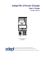
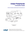
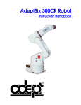
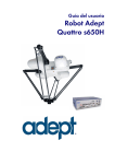
Adept PA-4 Power Chassis
User’s Guide
for PA-4 CAT-3
J-AMP
J-AMP
s DAI
J-AMP
CAUTION
HIGH
VOLTAGE
INSIDE
DO NOT REMOVE OR INSTALL THIS
MODULE UNLESS HIGH VOLTS LED
IS COMPLETELY DISTINGUISHED
DO NOT REMOVE OR INSTALL THIS
MODULE UNLESS HIGH VOLTS LED
IS COMPLETELY DISTINGUISHED
HIGH VOLTS ON
DO NOT REMOVE OR INSTALL THIS
MODULE UNLESS HIGH VOLTS LED
IS COMPLETELY DISTINGUISHED
HIGH VOLTS ON
HIGH VOLTS ON
PWM ON
PWM ON
PWM ON
LOW VOLTS ON
LOW VOLTS ON
LOW VOLTS ON
OPEN CKT FAULT
OPEN CKT FAULT
OPEN CKT FAULT
HV SAG/OVER TEMP FAULT
HV SAG/OVER TEMP FAULT
HV SAG/OVER TEMP FAULT
SHORT FAULT
SHORT FAULT
CH1 CH2
B
R
A
K
E
1
SmartServo
SHORT FAULT
CH1 CH2
CH1 CH2
2
STATUS
R
S
2
3
2
E
X
P
I
O
A
M
P
L
I
F
I
E
R
C
O
N
T
R
O
L
CH1
®
CH2
CH1
CH2
X
S
L
V
CH1
M
O
T
O
R
M
O
T
O
R
M
O
T
O
R
P
O
W
E
R
P
O
W
E
R
P
O
W
E
R
O
U
T
P
U
T
O
U
T
P
U
T
O
U
T
P
U
T
CH2
C
N
P
G
4
5
6
C
N
P
G
1
2
3
C
N
2
5
C
N
2
9
adept
technology, inc.
Adept PA-4 Power Chassis
User’s Guide
for PA-4 CAT-3
J-AMP
J-AMP
s DAI
J-AMP
CAUTION
HIGH
VOLTAGE
INSIDE
DO NOT REMOVE OR INSTALL THIS
MODULE UNLESS HIGH VOLTS LED
IS COMPLETELY DISTINGUISHED
DO NOT REMOVE OR INSTALL THIS
MODULE UNLESS HIGH VOLTS LED
IS COMPLETELY DISTINGUISHED
HIGH VOLTS ON
DO NOT REMOVE OR INSTALL THIS
MODULE UNLESS HIGH VOLTS LED
IS COMPLETELY DISTINGUISHED
HIGH VOLTS ON
HIGH VOLTS ON
PWM ON
PWM ON
PWM ON
LOW VOLTS ON
LOW VOLTS ON
LOW VOLTS ON
OPEN CKT FAULT
OPEN CKT FAULT
HV SAG/OVER TEMP FAULT
OPEN CKT FAULT
HV SAG/OVER TEMP FAULT
SHORT FAULT
HV SAG/OVER TEMP FAULT
SHORT FAULT
CH1 CH2
B
R
A
K
E
1
SmartServo
SHORT FAULT
CH1 CH2
CH1 CH2
2
STATUS
R
S
2
3
2
E
X
P
I
O
A
M
P
L
I
F
I
E
R
C
O
N
T
R
O
L
CH1
®
CH2
CH1
CH2
X
S
L
V
CH1
M
O
T
O
R
M
O
T
O
R
M
O
T
O
R
P
O
W
E
R
P
O
W
E
R
P
O
W
E
R
O
U
T
P
U
T
O
U
T
P
U
T
O
U
T
P
U
T
CH2
C
N
P
G
4
5
6
C
N
P
G
1
2
3
C
N
2
5
C
N
2
9
adept
technology, inc.
P/N: 02725-000, Rev D
August 2007
3011 Triad Drive • Livermore, CA 94551 • USA • Phone 925.245.3400 • Fax 925.960.0452
Otto-Hahn-Strasse 23 • 44227 Dortmund • Germany • Phone +49.231.75.89.40 • Fax +49.231.75.89.450
151 Lorong Chuan #04-07 • New Tech Park, Lobby G • Singapore 556741 • Phone +65.6281.5731 • Fax +65.6280.5714
The information contained herein is the property of Adept Technology, Inc., and shall not be reproduced
in whole or in part without prior written approval of Adept Technology, Inc. The information herein is subject to change without notice and should not be construed as a commitment by Adept Technology, Inc. This
manual is periodically reviewed and revised.
Adept Technology, Inc., assumes no responsibility for any errors or omissions in this document. Critical
evaluation of this manual by the user is welcomed. Your comments assist us in preparation of future documentation. Please email your comments to: [email protected].
Copyright © 2005-2007 by Adept Technology, Inc. All rights reserved.
Adept, the Adept logo, the Adept Technology logo, AdeptVision, AIM, Blox, Bloxview, FireBlox, Fireview,
HexSight, Meta Controls, MetaControls, Metawire, Soft Machines, and Visual Machines are registered
trademarks of Adept Technology, Inc. Brain on Board is a registered trademark of Adept Technology, Inc.
in Germany.
ACE, ActiveV, Adept 1060 / 1060+, Adept 1850 / 1850 XP, Adept 540 Adept 560, Adept AnyFeeder, Adept
Award, Adept C40, Adept C60, Adept CC, Adept Cobra 350, Adept Cobra 350 CR/ESD, Adept Cobra 550,
Adept 550 CleanRoom, Adept Cobra 600, Adept Cobra 800, Adept Cobra i600, Adept Cobra i800, Adept
Cobra PLC server, Adept Cobra PLC800, Adept Cobra s600, Adept Cobra s800, Adept Cobra s800 Inverted,
Adept Cobra Smart600, Adept Cobra Smart800, Adept DeskTop, Adept FFE, Adept FlexFeeder 250, Adept
IC, Adept iSight, Adept Impulse Feeder, Adept LineVision, Adept MB-10 ServoKit, Adept MC, Adept
MotionBlox-10, Adept MotionBlox-40L, Adept MotionBlox-40R, Adept MV Adept MV-10, Adept MV-19,
Adept MV4, Adept MV-5, Adept MV-8, Adept OC, Adept Python, Adept sDIO, Adept SmartAmp, Adept
SmartAxis, Adept SmartController CS, Adept SmartController CX, Adept SmartModule, Adept
SmartMotion, Adept SmartServo, Adept sMI6, Adept sSight, Adept Viper s650, Adept Viper s850, Adept
Viper s1300, Adept Viper s1700, AdeptCartesian, AdeptCast, AdeptForce, AdeptFTP, AdeptGEM,
AdeptModules, AdeptMotion, AdeptMotion Servo, AdeptMotion VME, AdeptNet, AdeptNFS,
AdeptOne, AdeptOne-MV, AdeptOne-XL, AdeptRAPID, AdeptSight, AdeptSix, AdeptSix 300, AdeptSix
300 CL, AdeptSix 300 CR, AdeptSix 600, AdeptTCP/IP, AdeptThree, AdeptThree-MV, AdeptThree-XL,
AdeptTwo, AdeptVision, AVI AdeptVision, AGS AdeptVision GV, AdeptVision I, AdeptVision II,
AdeptVision VME, AdeptVision VXL, AdeptVision XGS, AdeptVision XGS II, AdeptWindows,
AdeptWindows Controller, AdeptWindows DDE, AdeptWindows Offline Editor, AdeptWindows PC,
AIM Command Server, AIM Dispense, AIM PCB, AIM VisionWare, A-Series, FlexFeedWare, HyperDrive,
IO Blox, IO Blox, 88, MicroV+, MotionBlox, MotionWare, ObjectFinder, ObjectFinder 2000, PackOne,
PalletWare, sAVI, S-Series, UltraOne, V, V+ and VisionTeach are trademarks of Adept Technology, Inc.
Any trademarks from other companies used in this publication
are the property of those respective companies.
Printed in the United States of America
Table of Contents
1
Introduction . . . . . . . . . . . . . . . . . . . . . . . . . . . . . . . . . . . . . . . . . . . . . . . . 9
1.1 Manual Overview . . . . . . . . . . . . . . . . . . . . . . . . . . . . . . . . . . . . . . . . . . . . . . . . . . 9
1.2 Environmental and Facility Requirements . . . . . . . . . . . . . . . . . . . . . . . . . . . . . 10
1.3 Compatibility Information . . . . . . . . . . . . . . . . . . . . . . . . . . . . . . . . . . . . . . . . . . 11
1.4 How Can I Get Help? . . . . . . . . . . . . . . . . . . . . . . . . . . . . . . . . . . . . . . . . . . . . . . 13
Related Manuals . . . . . . . . . . . . . . . . . . . . . . . . . . . . . . . . . . . . . . . . . . . . . . . 13
Adept Document Library . . . . . . . . . . . . . . . . . . . . . . . . . . . . . . . . . . . . . . . . 14
1.5 Safety . . . . . . . . . . . . . . . . . . . . . . . . . . . . . . . . . . . . . . . . . . . . . . . . . . . . . . . . . . . 14
Warnings, Cautions, and Notes . . . . . . . . . . . . . . . . . . . . . . . . . . . . . . . . . . . 14
Reading and Training for Users and Operators . . . . . . . . . . . . . . . . . . . . . . 15
Additional Safety Information . . . . . . . . . . . . . . . . . . . . . . . . . . . . . . . . . . . . 16
2
Mounting the PA-4 Chassis . . . . . . . . . . . . . . . . . . . . . . . . . . . . . . . . . . . 19
2.1 Space Around the Chassis . . . . . . . . . . . . . . . . . . . . . . . . . . . . . . . . . . . . . . . . . . 19
2.2 Panel or Rack Mounting . . . . . . . . . . . . . . . . . . . . . . . . . . . . . . . . . . . . . . . . . . . . 20
Panel Mounting . . . . . . . . . . . . . . . . . . . . . . . . . . . . . . . . . . . . . . . . . . . . . . . . 20
Rack Mounting . . . . . . . . . . . . . . . . . . . . . . . . . . . . . . . . . . . . . . . . . . . . . . . . 20
2.3 Adept PA-4 Dimensions . . . . . . . . . . . . . . . . . . . . . . . . . . . . . . . . . . . . . . . . . . . . 22
3
Installation for Adept Viper Robots . . . . . . . . . . . . . . . . . . . . . . . . . . . . 25
3.1 Overview . . . . . . . . . . . . . . . . . . . . . . . . . . . . . . . . . . . . . . . . . . . . . . . . . . . . . . . . 25
3.2 H, I, J, and K Amplifier Modules . . . . . . . . . . . . . . . . . . . . . . . . . . . . . . . . . . . . . . 29
3.3 sDAI Module . . . . . . . . . . . . . . . . . . . . . . . . . . . . . . . . . . . . . . . . . . . . . . . . . . . . . 31
3.4 PA-4 Connectors . . . . . . . . . . . . . . . . . . . . . . . . . . . . . . . . . . . . . . . . . . . . . . . . . . 33
Arm Power/Signal Connector . . . . . . . . . . . . . . . . . . . . . . . . . . . . . . . . . . . . 33
Power and Encoder Connectors . . . . . . . . . . . . . . . . . . . . . . . . . . . . . . . . . . 33
External Brake Connector . . . . . . . . . . . . . . . . . . . . . . . . . . . . . . . . . . . . . . . . 33
3.5 Removing the Interface Box . . . . . . . . . . . . . . . . . . . . . . . . . . . . . . . . . . . . . . . . 34
4
Installation for AdeptSix Robots . . . . . . . . . . . . . . . . . . . . . . . . . . . . . . . 35
4.1 Overview . . . . . . . . . . . . . . . . . . . . . . . . . . . . . . . . . . . . . . . . . . . . . . . . . . . . . . . . 35
4.2 Dual Amplifier Modules . . . . . . . . . . . . . . . . . . . . . . . . . . . . . . . . . . . . . . . . . . . . 37
4.3 sMAI Module . . . . . . . . . . . . . . . . . . . . . . . . . . . . . . . . . . . . . . . . . . . . . . . . . . . . . 38
Adept PA-4 Power Chassis User’s Guide, Rev D
5
Table of Contents
5
Installation for AdeptOne Robots . . . . . . . . . . . . . . . . . . . . . . . . . . . . . . 41
5.1 Overview. . . . . . . . . . . . . . . . . . . . . . . . . . . . . . . . . . . . . . . . . . . . . . . . . . . . . . . . . 41
5.2 A Amplifier Modules . . . . . . . . . . . . . . . . . . . . . . . . . . . . . . . . . . . . . . . . . . . . . . . 42
5.3 B+ Amplifier Module . . . . . . . . . . . . . . . . . . . . . . . . . . . . . . . . . . . . . . . . . . . . . . . 43
5.4 sEJI Amplifier Module . . . . . . . . . . . . . . . . . . . . . . . . . . . . . . . . . . . . . . . . . . . . . . 44
6
Maintenance . . . . . . . . . . . . . . . . . . . . . . . . . . . . . . . . . . . . . . . . . . . . . . 45
6.1 Adept PA-4 Air Filter Inspection and Cleaning . . . . . . . . . . . . . . . . . . . . . . . . . . 45
6.2 PA-4 Power Chassis Circuit Breaker and Fuse Information . . . . . . . . . . . . . . . . 46
Chassis Circuit Breaker . . . . . . . . . . . . . . . . . . . . . . . . . . . . . . . . . . . . . . . . . . . 46
Chassis and Amplifier Module Fuses . . . . . . . . . . . . . . . . . . . . . . . . . . . . . . . . 46
6.3 Removing and Installing Amplifier and Control Modules . . . . . . . . . . . . . . . . . 46
Removing Amplifier Modules . . . . . . . . . . . . . . . . . . . . . . . . . . . . . . . . . . . . . 47
Installing Amplifier Modules . . . . . . . . . . . . . . . . . . . . . . . . . . . . . . . . . . . . . . . 47
6.4 PA-4 CAT-3 Power Chassis LED Functions . . . . . . . . . . . . . . . . . . . . . . . . . . . . . . 48
6.5 Changing the Power Chassis Voltage Setting . . . . . . . . . . . . . . . . . . . . . . . . . . 49
Changing From 380-415 VAC to 200-240 VAC . . . . . . . . . . . . . . . . . . . . . . . . 49
Part 1 – Insulating the Power Chassis Power Cord . . . . . . . . . . . . . . 49
Part 2 – Rotating the Voltage Selector in the Power Chassis . . . . . 50
Changing From 200-240 VAC to 380-415 VAC . . . . . . . . . . . . . . . . . . . . . . . . 51
Part 1 – Rotating the Voltage Selector in the Power Chassis . . . . . 51
Part 2 – Insulating the Power Chassis Power Cord . . . . . . . . . . . . . . 51
Index . . . . . . . . . . . . . . . . . . . . . . . . . . . . . . . . . . . . . . . . . . . . . . . . . . . . . . . . 53
6
Adept PA-4 Power Chassis User’s Guide, Rev D
List of Figures
Figure 1-1.
Adept PA-4 Power Chassis . . . . . . . . . . . . . . . . . . . . . . . . . . . . . . . . . . . . . . . . . 9
Figure 1-2.
Product ID Label for CAT-3 PA-4 . . . . . . . . . . . . . . . . . . . . . . . . . . . . . . . . . . . 11
Figure 2-1.
Installing Mounting Brackets on an Adept PA-4 Chassis . . . . . . . . . . . . . . . 21
Figure 2-2.
Adept PA-4 Power Chassis Dimensions for Adept Viper . . . . . . . . . . . . . . . . 22
Figure 2-3.
Basic Adept PA-4 Power Chassis Dimensions (Without Modules) . . . . . . . . 23
Figure 2-4.
PA-4 Dimensions With Mounting Brackets Installed . . . . . . . . . . . . . . . . . . . 24
Figure 3-1.
Adept PA-4 Power Chassis with sDAI Module (Viper s650/s850 Robots) . . . 26
Figure 3-2.
Adept PA-4 Power Chassis with sDAI 100W Module (Viper s1300 Robots) . 27
Figure 3-3.
Adept PA-4 Power Chassis with sDAI HP Module (Viper s1700 Robots) . . . 28
Figure 3-4.
J Amplifier Module Connectors and Indicators . . . . . . . . . . . . . . . . . . . . . . . 30
Figure 3-5.
sDAI Module Connectors and Indicators . . . . . . . . . . . . . . . . . . . . . . . . . . . . 31
Figure 3-6.
External Brake Connector Pinouts . . . . . . . . . . . . . . . . . . . . . . . . . . . . . . . . . 33
Figure 3-7.
PA-4 with Interface Box Tilted Open . . . . . . . . . . . . . . . . . . . . . . . . . . . . . . . . 34
Figure 4-1.
Adept PA-4 Power Chassis with sMAI Module . . . . . . . . . . . . . . . . . . . . . . . . 36
Figure 4-2.
Dual Amplifier Module Connectors and Indicators . . . . . . . . . . . . . . . . . . . 37
Figure 4-3.
sMAI Module Connectors and Indicators . . . . . . . . . . . . . . . . . . . . . . . . . . . 38
Figure 5-1.
PA-4 with sEJI Module . . . . . . . . . . . . . . . . . . . . . . . . . . . . . . . . . . . . . . . . . . . . 41
Figure 5-2.
A Amplifier Connectors and Indicators . . . . . . . . . . . . . . . . . . . . . . . . . . . . . 42
Figure 5-3.
B+ Amplifier Connectors and Indicators . . . . . . . . . . . . . . . . . . . . . . . . . . . . . 43
Figure 5-4.
sEJI Module Connectors and Indicators . . . . . . . . . . . . . . . . . . . . . . . . . . . . . 44
Figure 6-1.
PA-4 Chassis LED Locations . . . . . . . . . . . . . . . . . . . . . . . . . . . . . . . . . . . . . . . 48
Figure 6-2.
Insulating Blue Wire in Power Cord (200-240 VAC) . . . . . . . . . . . . . . . . . . . . 50
Figure 6-3.
Changing Voltage in Power Chassis . . . . . . . . . . . . . . . . . . . . . . . . . . . . . . . . 50
Figure 6-4.
Removing Insulation from Blue Wire in Power Cord (380-415 VAC) . . . . . . 52
Adept PA-4 Power Chassis User’s Guide, Rev D
7
Introduction
1.1
1
Manual Overview
This manual describes the installation and maintenance of the Adept PA-4 CAT-3 power
chassis as it is used in the:
• Adept Viper robot product line (see Chapter 3)
• AdeptSix robot product line (see Chapter 4)
• AdeptOne robot with the Adept SmartController product line (see Chapter 5)
The following chapters apply to all three families of robots:
• Chapter 1 - Introduction
• Chapter 2 - Mounting the PA-4 Chassis
• Chapter 6 - Maintenance
J-AMP
DO NOT REMOVE OR INSTALL THIS
MODULE UNLESS HIGH VOLTS LED
IS COMPLETELY DISTINGUISHED
J-AMP
J-AMP
DO NOT REMOVE OR INSTALL THIS
MODULE UNLESS HIGH VOLTS LED
IS COMPLETELY DISTINGUISHED
DO NOT REMOVE OR INSTALL THIS
MODULE UNLESS HIGH VOLTS LED
IS COMPLETELY DISTINGUISHED
HIGH VOLTS ON
HIGH VOLTS ON
PWM ON
HIGH VOLTS ON
PWM ON
LOW VOLTS ON
PWM ON
LOW VOLTS ON
OPEN CKT FAULT
LOW VOLTS ON
OPEN CKT FAULT
HV SAG/OVER TEMP FAULT
OPEN CKT FAULT
HV SAG/OVER TEMP FAULT
SHORT FAULT
HV SAG/OVER TEMP FAULT
SHORT FAULT
CH1 CH2
SHORT FAULT
CH1 CH2
CH1 CH2
A
M
P
L
I
F
I
E
R
C
O
N
T
R
O
L
CH1
®
CH1
CH2
CH2
CH1
M
O
T
O
R
M
O
T
O
R
M
O
T
O
R
P
O
W
E
R
P
O
W
E
R
P
O
W
E
R
O
U
T
P
U
T
O
U
T
P
U
T
O
U
T
P
U
T
CH2
adept
technology, inc.
Figure 1-1. Adept PA-4 Power Chassis
NOTE: This PA-4 CAT-3 is also compatible with earlier Adept products.
See Section 1.3 on page 11.
Adept PA-4 Power Chassis User’s Guide, Rev D
9
Chapter 1 - Introduction
1.2
Environmental and Facility Requirements
The Adept PA-4 installation must meet the operating environment requirements shown
in Table 1-1. See the robot manual that came with your system for environment
requirements for the robot.
Table 1-1. Adept PA-4 Operating Environment Requirements
Ambient temperature
5° to 40°C (41° to 104°F)
Humidity
5 to 90%, noncondensing
Altitude
up to 2000 m (6500 ft)
Pollution degree
2 (IEC 1131-2/EN 61131-2)
Free space around power chassis for proper
cooling
50 mm (2 inches) in front
25 mm (1 inch) at top
Power chassis subassembly protection class,
unmounted
IP20 (NEMA Type 1)
Recommendations for customer-supplied
enclosure for Adept power chassis (mandatory
for installations in EU or EEA countries).
Enclosure should meet EN 60204 (IEC 204)
requirements and be rated at IP54. Also,
enclosure must provide a method of locking
the enclosure power-disconnect in the OFF
position.
10
Adept PA-4 Power Chassis User’s Guide, Rev D
Manual Overview
1.3
Compatibility Information
The CAT-3 version of the PA-4, P/N 01044-000, was developed primarily to support the
Category 3 robot systems. You can identify this new version of the PA-4 from earlier
versions in two ways:
• the product ID label with the new part number 01044-000, located on the right side
of the chassis. See Figure 1-2.
• on the lower-right side of the PA-4 front panel, there are additional labels for
diagnostic LEDs. See Figure 6-1 on page 48.
This new PA-4 is also backwards compatible with earlier Adept systems, such as Adept
Cobra and Adept XL robots. See Table 1-2 on page 12.
NOTE: The CAT-3 version of the PA-4 in AdeptSix robot systems must
use the sMAI (smart Multi-Axis Interface) or MAI-2 module; it is not
compatible with the earlier MAI-1 module.
Figure 1-2. Product ID Label for CAT-3 PA-4
Adept PA-4 Power Chassis User’s Guide, Rev D
11
Chapter 1 - Introduction
Table 1-2. PA-4 Plug-in Module Compatibility
Modules Compatible with CAT-3 PA-4
Robot Control Modules
sDAI module
Adept Viper s650/s850 robot systems
sDAI-100W
Adept Viper s1300 robot systems
sDAI-HP
Adept Viper s1700 robot systems
sMAI module
PA-4 for all AdeptSix robot systems, starting in
October 2004
MAI-2 module
PA-4 prior to introduction of sMAI module
sEJI module
AdeptOne robot systems
Amplifier Modules
H and I Amps
Adept Viper s1700 robots
J Amp
Adept Viper s650/s850 robots (with PA-4) and Adept
Viper s1300 robots
K Amp
Adept Viper s1300 robots
Dual E Amp
AdeptSix 300 and 300CR robots
Dual F and Dual G Amps
AdeptSix 600 robots
A, B+, and Dual B+ Amps
AdeptOne with SmartController, AdeptOne-XL, and
AdeptThree-XL robots
Dual B+II Amp
AdeptVicron 300S robot
Dual C Amp
Adept Cobra 600 and 800 robots
MV-4 Insert
Used when PA-4 is configured as a Compact
Controller
Modules NOT Compatible with CAT-3 PA-4
MAI-1 (just MAI on label)
12
The original MAI module was used in early A6 300
robot systems. This module can only be used in the
earlier PA-4, P/N 30336-31000.
Adept PA-4 Power Chassis User’s Guide, Rev D
Manual Overview
1.4
How Can I Get Help?
Refer to the How to Get Help Resource Guide (Adept P/N 00961-00700) for details on
getting assistance with your Adept software and hardware.
Additionally, you can access information sources on Adept’s corporate Web
site:
http://www.adept.com
Related Manuals
This manual covers the installation, operation, and maintenance of an Adept PA-4 power
chassis. There are additional manuals that cover programming the system, reconfiguring
installed components, and adding other optional components; see Table 1-3. These
manuals are available on the Adept Document Library CD-ROM shipped with each
system.
Table 1-3. Related Manuals
Manual Title
Description
AdeptSix 300 Robot
Instruction Handbook
Contains complete information on the installation and operation
of the AdeptSix 300, AdeptSix 300CR, and AdeptSix 600
robots.
AdeptSix 300CR Robot
Instruction Handbook
AdeptSix 600 Robot
Instruction Handbook
AdeptViper s650/s850 Robot
User’s Guide
AdeptViper s1300 Robot
User’s Guide
Contains complete information on the installation and operation
of the Adept Viper s650/s850, Adept Viper s1300, and Adept
Viper s1700 robots.
AdeptViper s1700 Robot
User’s Guide
AdeptOne with
SmartControler User’s
Guide
Contains complete information on the installation and operation
of the AdeptOne with SmartController robot.
Adept SmartController
User’s Guide
Contains complete information on the installation and operation
of the Adept SmartController.
AdeptWindows Installation
Guide
Describes complex network installation, installation and use of
NFS server software, the AdeptWindows Offline Editor, and the
AdeptWindows DDE software.
Adept PA-4 Power Chassis User’s Guide, Rev D
13
Chapter 1 - Introduction
Adept Document Library
The Adept Document Library (ADL) contains documentation for Adept products. You
can access the ADL from:
• the Adept Software CD shipped with your system
• the separate ADL CD shipped with your system.
• the Adept Web site. Select Document Library from the Adept home page. To go
directly to the Adept Document Library, type the following URL into your
browser:
http://www.adept.com/Main/KE/DATA/adept_search.htm
To locate information on a specific topic, use the Document Library search engine on the
ADL main page. To view a list of available product documentation, select the Document
Titles option.
1.5
Safety
The Adept PA-4 operates on either 200-240 VAC or 380-415 VAC. You must be very
careful when installing and operating these products. Read and understand the Safety
chapter in your robot manual before attempting to install these products. Observe all
warnings in this manual and in the robot and controller manuals as you set up your
Adept system.
Warnings, Cautions, and Notes
There are four levels of special alert notation used in this manual. In descending order of
importance, they are:
DANGER: This indicates an imminently hazardous
situation which, if not avoided, will result in death or
serious injury.
WARNING: This indicates a potentially hazardous
situation which, if not avoided, could result in serious
injury or major damage to the equipment.
14
Adept PA-4 Power Chassis User’s Guide, Rev D
Safety
CAUTION: This indicates a situation which, if not avoided,
could result in minor injury or damage to the equipment.
NOTE: This provides supplementary information, emphasizes a point or
procedure, or gives a tip for easier operation.
Reading and Training for Users and Operators
Adept systems can include computer-controlled mechanisms that are capable of moving
at high speeds and exerting considerable force. Like all robot and motion systems, and
most industrial equipment, they must be treated with respect by the user and the
operator.
This manual should be read by all personnel who operate or maintain Adept systems, or
who work within or near the workcell.
The installation and use of Adept products must comply with all safety instructions and
warnings in this manual. Installation and use must also comply with all applicable local
and national requirements and safety standards.
We recommend you read the American National Standard for Industrial Robot Systems Safety Requirements, published by the Robotic Industries Association (RIA) in conjunction
with the American National Standards Institute. The publication, ANSI/RIA R15.06,
contains guidelines for robot system installation, safeguarding, maintenance, testing,
startup, and operator training.
We also recommend you read the International Standard IEC 204 or the European
Standard EN 60204, Safety of Machinery – Electrical Equipment of Machines, and ISO 10218
(EN 775), Manipulating Industrial Robots – Safety, particularly if the country of use requires
a CE-certified installation.
This manual assumes that the user has attended an Adept training course and has a basic
working knowledge of the system. The user should provide the necessary additional
training for all personnel who will be working with the system.
Adept PA-4 Power Chassis User’s Guide, Rev D
15
Chapter 1 - Introduction
Additional Safety Information
The standards and regulations listed in this manual contain additional guidelines for
robot system installation, safeguarding, maintenance, testing, start-up, and operator
training. Table 1-4 lists some sources for the various standards.
.
Table 1-4. Sources for International Standards and Directives
SEMI International Standards
3081 Zanker Road
San Jose, CA 95134
USA
American National Standards Institute (ANSI)
11 West 42nd Street, 13th Floor
New York, NY 10036
USA
Phone: 1.408.943.6900
Fax: 1.408.428.9600
Phone 212-642-4900
Fax 212-398-0023
http://www.semi.org/
http://www.ansi.org
BSI Group (British Standards)
389 Chiswick High Road
London W4 4AL
United Kingdom
Document Center, Inc.
1504 Industrial Way, Unit 9
Belmont, CA 94002
USA
Phone +44 (0)20 8996 9000
Fax +44 (0)20 8996 7400
Phone 415-591-7600
Fax 415-591-7617
http://www.bsi-global.com
http://www.document-center.com
DIN, Deutsches Institut für Normung e.V.
German Institute for Standardization
Burggrafenstrasse 6
10787 Berlin
Germany
Global Engineering Documents
15 Inverness Way East
Englewood, CO 80112
USA
Phone 800-854-7179
Fax 303-397-2740
Phone.: +49 30 2601-0
Fax: +49 30 2601-1231
http://global.ihs.com
http://www.din.de
http://www2.beuth.de/ (publishing)
IEC, International Electrotechnical Commission
Rue de Varembe 3
PO Box 131
CH-1211 Geneva 20
Switzerland
Robotic Industries Association (RIA)
900 Victors Way
PO Box 3724
Ann Arbor, MI 48106
USA
Phone 41 22 919-0211
Fax 41 22 919-0300
Phone 313-994-6088
Fax 313-994-3338
http://www.iec.ch
http://www.robotics.org
16
Adept PA-4 Power Chassis User’s Guide, Rev D
Safety
Table 1-4. Sources for International Standards and Directives (Continued)
Underwriters Laboratories Inc.
333 Pfingsten Road
Northbrook, IL 60062-2096 USA
Phone: +1-847-272-8800
Fax: +1-847-272-8129
http://www.ul.com/
Adept PA-4 Power Chassis User’s Guide, Rev D
17
Mounting the PA-4 Chassis
2
The PA-4 chassis must be installed in a suitable enclosure that provides the environment
(temperature, etc.) specified in Table 1-1 on page 10. The enclosure must also provide a
power disconnect with a method for user service personnel to lock the power in the OFF
position. This is required for safety, including national and international standards, such
as:
• OSHA ‘Lockout/Tagout’ (USA)
• IEC 204-1
• EN 60204-1
DANGER: Failure to provide and use a suitable disconnect
device could cause death or injury to personnel.
2.1
Space Around the Chassis
When the PA-4 chassis is installed, you must allow 50 mm (2 in) at the front of the chassis
and 25 mm (1 in.) at the top of the chassis for proper air cooling.
CAUTION: It is important to keep the air filters clean so the
forced air cooling system can work efficiently. See
Section 6.1 on page 45 for details on cleaning the filters.
Adept PA-4 Power Chassis User’s Guide, Rev D
19
Chapter 2 - Mounting the PA-4 Chassis
2.2
Panel or Rack Mounting
The PA-4 chassis can be panel or rack mounted using the optional mounting brackets
(P/N 90336-31030F). The brackets can be attached at the rear of the PA-4 chassis for panel
mounting, or they can be attached to the front of the PA-4 chassis for rack mounting.
NOTE: Using screws other than those supplied could cause an electrical
short. There is a printed circuit board at the bottom of the chassis and
screws, other than those supplied, could come into contact with electrical
components or pinch wires.
Panel Mounting
To panel-mount the PA-4 chassis, install one bracket on each side near the back of the
chassis. Use the screws and washers from the accessories kit (see Figure 2-1 on page 21).
Rack Mounting
Use the mounting brackets, screws, and washers to rack-mount the PA-4 chassis in a
standard 19-inch equipment rack. You must build an extender panel and attach it to the
mounting brackets. The brackets can be installed in two positions for rack mounting:
“flush” and “set-back” (see Figure 2-1 on page 21).
NOTE: The rack-mounting option is not available for PA-4 power chassis
shipped with Adept Viper systems.
20
Adept PA-4 Power Chassis User’s Guide, Rev D
Space Around the Chassis
M4 x 10 mm pan-head screw
(2 places)
To Install Mounting Brackets on Adept PA-4
Power Chassis:
• Remove (and discard) 3 existing countersunk
screws from side of chassis at locations shown
in drawing.
• Place bracket in desired position and secure
with indicated M4 pan-head screws and washers from
accessories kit.
• Repeat process for other side of chassis.
M4 x 10 mm pan-head screw
Panel Mount
M4 x 10 mm pan-head screw
(2 places)
M4 x 10 mm pan-head screw
Rack Mount – Flush
M4 x 10 mm pan-head screw
(2 places)
M4 x 10 mm pan-head screw
Rack Mount – Set-Back
Figure 2-1. Installing Mounting Brackets on an Adept PA-4 Chassis
NOTE: See Section 2.3 on page 22 for PA-4 dimensions.
Adept PA-4 Power Chassis User’s Guide, Rev D
21
Chapter 2 - Mounting the PA-4 Chassis
WARNING: Do not turn on AC power to the PA-4 until
you have completed installation of the robot, controller,
and any additional equipment. Refer to your robot manual
to verify system installation and activate system power.
Refer to your robot manual for information on PA-4 chassis power requirements and
instructions on connecting AC power to the PA-4 chassis.
2.3
Adept PA-4 Dimensions
216
®
95
357
®
219
220
95
479
136
18
Figure 2-2. Adept PA-4 Power Chassis Dimensions for Adept Viper
22
Adept PA-4 Power Chassis User’s Guide, Rev D
Adept PA-4 Dimensions
290 mm
(11.4 in.)
Top View
290 mm
(11.4 in.)
216 mm
(8.5 in.)
479 mm
(18.9 in.)
adept
technology, inc.
136 mm
(5.4 in.)
Front View
18 mm
(0.7 in.)
Side View
Figure 2-3. Basic Adept PA-4 Power Chassis Dimensions (Without Modules)
Adept PA-4 Power Chassis User’s Guide, Rev D
23
Chapter 2 - Mounting the PA-4 Chassis
266 mm
(10.47 in.)
3.2 mm
(0.13 in.)
22.2 mm
(0.87 in.)
133.35 mm
(5.25 in.)
adept
technology, inc.
479 mm
(18.8 in.)
146.05 mm
(5.75 in.)
PA-4 Power Chassis with
mounting brackets installed
133.35 mm
(5.25 in.)
6.8 mm
(0.27 in.)
(4x)
8.56 mm
(0.34 in.)
33.1 mm
(1.30 in.)
10.3 mm
(0.41 in.)
(4x)
Figure 2-4. PA-4 Dimensions With Mounting Brackets Installed
24
Adept PA-4 Power Chassis User’s Guide, Rev D
Installation for Adept Viper
Robots
3.1
3
Overview
The PA-4 CAT-3 includes AC-DC power conversion electronics that support a range of
Adept power amplifiers and robot control modules. In addition, the PA-4 CAT-3 includes
dual (redundant) high-power AC contactors that, in combination with the sDAI, meet the
Category-3 E-Stop requirements per EN-954. The PA-4 is configured with the following
amplifier modules to support the Adept Viper robot systems listed below.
• Viper s1700: H and I amps
• Viper s1300: J and K amps
• Viper s650/s850 (with PA-4): J amps
The amplifiers in the Adept Viper robot system are controlled by an sDAI
distributed-control module. The sDAI module resides in the PA-4 chassis and contains a
RISC microprocessor and interface circuitry that close the servo loops for
high-performance robot motion. The sDAI is connected to a host Adept SmartController
via the SmartServo interface (based on IEEE 1394, also called “FireWire®”).
NOTE: The Adept Viper s1300 uses the 100W version of the sDAI; the
Adept Viper s1700 uses the HP version of the sDAI.
Adept PA-4 Power Chassis User’s Guide, Rev D
25
Chapter 3 - Installation for Adept Viper Robots
J Amp
J Amp
J Amp
sDAI Module
J-AMP
J-AMP
J-AMP
s DAI
CAUTION
HIGH
VOLTAGE
INSIDE
DO NOT REMOVE OR INSTALL THIS
MODULE UNLESS HIGH VOLTS LED
IS COMPLETELY DISTINGUISHED
DO NOT REMOVE OR INSTALL THIS
MODULE UNLESS HIGH VOLTS LED
IS COMPLETELY DISTINGUISHED
DO NOT REMOVE OR INSTALL THIS
MODULE UNLESS HIGH VOLTS LED
IS COMPLETELY DISTINGUISHED
HIGH VOLTS ON
HIGH VOLTS ON
HIGH VOLTS ON
PWM ON
PWM ON
PWM ON
LOW VOLTS ON
LOW VOLTS ON
LOW VOLTS ON
OPEN CKT FAULT
OPEN CKT FAULT
HV SAG/OVER TEMP FAULT
OPEN CKT FAULT
HV SAG/OVER TEMP FAULT
SHORT FAULT
HV SAG/OVER TEMP FAULT
SHORT FAULT
CH1 CH2
STATUS
1
R
S
2
3
2
SmartServo
SHORT FAULT
CH1 CH2
2
CH1 CH2
E
X
P
I
O
A
M
P
L
I
F
I
E
R
Latching Screws
C
O
N
T
R
O
L
X
S
L
V
®
Interface Box
C
N
P
G
4
5
6
C
N
P
G
1
2
3
CH1
Arm Power/Signal
Connector
B
R
A
K
E
CH1
CH2
CH2
CH1
M
O
T
O
R
M
O
T
O
R
M
O
T
O
R
P
O
W
E
R
P
O
W
E
R
P
O
W
E
R
O
U
T
P
U
T
O
U
T
P
U
T
O
U
T
P
U
T
CH2
C
N
2
5
C
N
2
9
External Brake
Connector
adept
technology, inc.
Figure 3-1. Adept PA-4 Power Chassis with sDAI Module (Viper s650/s850 Robots)
26
Adept PA-4 Power Chassis User’s Guide, Rev D
Overview
K-Amp
K-Amp
J-Amp
sDAI Module (100 W)
K-AMP
K-AMP
J-AMP
s DAI
Brake Release
CAUTION
HIGH
VOLTAGE
INSIDE
DO NOT REMOVE OR INSTALL THIS
MODULE UNLESS HIGH VOLTS LED
IS COMPLETELY DISTINGUISHED
DO NOT REMOVE OR INSTALL THIS
MODULE UNLESS HIGH VOLTS LED
IS COMPLETELY DISTINGUISHED
DO NOT REMOVE OR INSTALL THIS
MODULE UNLESS HIGH VOLTS LED
IS COMPLETELY DISTINGUISHED
HIGH VOLTS ON
HIGH VOLTS ON
HIGH VOLTS ON
PWM ON
PWM ON
PWM ON
LOW VOLTS ON
LOW VOLTS ON
OPEN CKT FAULT
OPEN CKT FAULT
HV SAG/OVER TEMP FAULT
SHORT FAULT
HV SAG/OVER TEMP FAULT
SHORT FAULT
1
R
S
2
3
2
SmartServo
SHORT FAULT
CH1 CH2
2
CH1 CH2
E
X
P
I
O
A
M
P
L
I
F
I
E
R
Latching Screws
C
O
N
T
R
O
L
X
S
L
V
®
Interface Box
CH1
CH2
CH2
CH1
M
O
T
O
R
M
O
T
O
R
M
O
T
O
R
P
O
W
E
R
P
O
W
E
R
P
O
W
E
R
O
U
T
P
U
T
O
U
T
P
U
T
O
U
T
P
U
T
RS-232
SmartServo 1 & 2
EXPIO
XSLV
C
N
P
G
4
5
6
C
N
P
G
1
2
3
CH1
Arm Power/Signal
Connector
Status Panel
STATUS
LOW VOLTS ON
OPEN CKT FAULT
HV SAG/OVER TEMP FAULT
CH1 CH2
B
R
A
K
E
CH2
C
N
2
5
C
N
2
9
External Brake
Connector
adept
technology, inc.
Figure 3-2. Adept PA-4 Power Chassis with sDAI 100W Module (Viper s1300 Robots)
Adept PA-4 Power Chassis User’s Guide, Rev D
27
Chapter 3 - Installation for Adept Viper Robots
H-Amp
I-Amp
H-Amp
sDAI Module (HP)
H-AMP
I-AMP
H-AMP
s DAI
Brake Release
CAUTION
HIGH
VOLTAGE
INSIDE
DO NOT REMOVE OR INSTALL THIS
MODULE UNLESS HIGH VOLTS LED
IS COMPLETELY DISTINGUISHED
DO NOT REMOVE OR INSTALL THIS
MODULE UNLESS HIGH VOLTS LED
IS COMPLETELY DISTINGUISHED
DO NOT REMOVE OR INSTALL THIS
MODULE UNLESS HIGH VOLTS LED
IS COMPLETELY DISTINGUISHED
HIGH VOLTS ON
HIGH VOLTS ON
HIGH VOLTS ON
PWM ON
PWM ON
PWM ON
LOW VOLTS ON
LOW VOLTS ON
OPEN CKT FAULT
OPEN CKT FAULT
HV SAG/OVER TEMP FAULT
SHORT FAULT
HV SAG/OVER TEMP FAULT
SHORT FAULT
1
R
S
2
3
2
SmartServo
SHORT FAULT
CH1 CH2
2
CH1 CH2
E
X
P
I
O
A
M
P
L
I
F
I
E
R
Latching Screws
C
O
N
T
R
O
L
X
S
L
V
®
Interface Box
CH1
CH2
M
O
T
O
R
M
O
T
O
R
P
O
W
E
R
P
O
W
E
R
O
U
T
P
U
T
O
U
T
P
U
T
CH2
CH1
RS-232
SmartServo 1 & 2
EXPIO
XSLV
C
N
P
G
4
5
6
C
N
P
G
1
2
3
CH1
Power Connector
Status Panel
STATUS
LOW VOLTS ON
OPEN CKT FAULT
HV SAG/OVER TEMP FAULT
CH1 CH2
B
R
A
K
E
CH2
C
N
2
5
Encoder Connector
C
N
2
9
adept
technology, inc.
Figure 3-3. Adept PA-4 Power Chassis with sDAI HP Module (Viper s1700 Robots)
The PA-4 CAT-3 features:
• AC-DC power conversion for amplifier modules
• Multiple amplifier/module support (4 slots)
• EN-954 Category 3 compliant E-Stop contactors
The sDAI module features:
• RISC microprocessor for servo loop control
• Interfaces to 6 axes of Adept power amplifiers
• Interfaces to robust digital serial absolute encoders
• Interfaces to 6 axes of electromechanical brakes
• Redundant E-Stop safety circuits.
• SmartServo (IEEE-1394) interface for distributed control
See Section 3.3 on page 31 for a description of the connectors and indicators on the sDAI.
28
Adept PA-4 Power Chassis User’s Guide, Rev D
H, I, J, and K Amplifier Modules
3.2
H, I, J, and K Amplifier Modules
The H and I Amplifier modules are plug-in modules that contain the circuitry and amplifying components for driving two of the motors in an Adept Viper s1700 robot. See Table
3-1.
The J Amplifier modules are plug-in modules that contain the circuitry and amplifying
components for driving two of the motors in an Adept Viper s650/s850 robot with PA-4
and two of the motors in an Adept Viper s1300 robot. See Table 3-1.
The K Amplifier modules are plug-in modules that contain the circuitry and amplifying
components for driving two of the motors in an Adept Viper s1300 robot. See Table 3-1.
Table 3-1. J Amplifier Functions
Amp Slot 1 (left)
Amp Slot 2 (center)
Amp Slot 3 (right)
Adept Viper s650/s850
Robot with PA-4
J Amp #1
drives motors 1 and 4
J Amp #2
drives motors 2 and 5
J Amp #3
drives motors 3 and 6
Adept Viper s1300
Robot
K Amp #1
drives motors 1 and 4
K Amp #2
drives motors 2 and 5
J Amp
drives motors 3 and 6
Adept Viper s1700
Robot
H Amp #1
drives motors 1 and 4
I Amp
drives motors 2 and 5
H Amp #2
drives motors 3 and 6
Adept PA-4 Power Chassis User’s Guide, Rev D
29
Chapter 3 - Installation for Adept Viper Robots
1. Status LEDs. The left column of LEDs is for the first motor
controlled by this module; the right column is for the second motor
controlled by this module. When an LED is turned on, it indicates
the following conditions:
J-AMP
DO NOT REMOVE OR INSTALL THIS
MODULE UNLESS HIGH VOLTS LED
IS COMPLETELY EXTINGUISHED
High Volts On indicates high voltage to the amps is turned on.
HIGH VOLTS ON
PWM ON
1
LOW VOLTS ON
OPEN CKT FAULT
HV SAG/OVER TEMP FAULT
SHORT FAULT
PWM On indicates that current servo is on. It does not go on until
calibration is complete.
CH1 CH2
Low Volts On indicates the low voltage supply in the power
chassis is on.
A
M
P
L
I
F
I
E
R
2
Note: the three LED pairs below indicate faults and are visible
momentarily before the system turns off.
C
O
N
T
R
O
L
Open Ckt Fault indicates that an open circuit in the motor leads
has been detected.
CH1
M
O
T
O
R
3
P
O
W
E
R
O
U
T
P
U
T
CH2
HV Sag/Over Temp Fault left LED, when lit, indicates that the fault
was caused by a sag in voltage. The right LED, when lit, indicates
the fault was caused by an over-temperature condition on the
amplifier heat sink.
Short Fault indicates that an over-current in the motor leads has
been detected.
2. Amplifier Control connector: the sDAI-to-Amp cable is installed
on this connector at the factory. This connector is covered by the
Interface Box.
3. Motor Power Outlet connectors: the Joint 1 to 6 power cables from
the Interface Box wiring harness are installed on these connectors.
Figure 3-4. J Amplifier Module Connectors and Indicators
NOTE: The above descriptions apply to the H, I, J, and K amplifier
modules.
30
Adept PA-4 Power Chassis User’s Guide, Rev D
sDAI Module
3.3
sDAI Module
The Adept sDAI module is a single-slot board designed to control the motion axes on an
Adept Viper robot. The sDAI connectors and indicators are described in Figure 3-5.
1. Brake connector: connects to the optional brake release box.
The brake release box is used to release the robot brakes
manually via a selector switch for each axis.
s DAI
CAUTION
HIGH
VOLTAGE
INSIDE
1
2
B
R
A
K
E
7
STATUS
1
SmartServo
2
R
S
2
3
2
8
3. Amplifier Signal connector: the sDAI-to-Amp interface cable
is installed on this connector at the factory. This connector is
covered when shipped and users should not need to access it.
E
X
P
I
O
9
4. CNPG123 connector: the CNPG123 plug on the Interface Box
wire harness is installed on this connector. Provides an
interface for the respective joint position encoders.
3
4
C
N
P
G
1
2
3
5
C
N
2
5
6
C
N
2
9
2. SmartServo ports 1 and 2: the IEEE-1394 cable from the
SmartServo connector on the SmartController can be
installed in port 1 or 2. This connection relays command and
control signals between the sDAI and the SmartController.
X
S
L
V
10
C
N
P
G
4
5
6
11
5. CN25 connector: the CN25 plug on the Interface Box wire
harness is installed on this connector.
6. CN29 connector: the CN29 plug on the Interface Box wire
harness is installed on this connector.
7. Status panel: displays alpha-numeric codes that indicate the
operating status of the robot, including detailed fault codes.
See Table 3-2 on page 32 for definitions of the status codes.
These codes provide details for quickly isolating problems
during troubleshooting.
8. RS-232 connector: reserved for future use.
9. EXPIO (EXPansion I/O) connector: this is the interface to
external IO devices, such as the IO Blox.
10. XSLV connector: interfaces to the XSYS connector on a
SmartController. The connection provides an interface so that
the sDAI is a slave to the dual-channel emergency stop
circuits of the controller.
11. CNPG456 connector: not used (except on Viper s1700 robot
systems).
Figure 3-5. sDAI Module Connectors and Indicators
NOTE: The above descriptions apply to the sDAI (used with the Adept
Viper s650/s850 with PA-4 robot), the sDAI 100W (used with the Adept
Viper s1300 robot,) and the sDAI HP (used with the Viper s1700 robot).
Adept PA-4 Power Chassis User’s Guide, Rev D
31
Chapter 3 - Installation for Adept Viper Robots
Table 3-2. Status Panel Codes
LED
Status Code
LED
Status Code
OK
No Fault
h#
High Temp Amp (Joint #)
ON
High Power ON Status
H#
High Temp Encoder (Joint #)
MA
Manual Mode
hV
High Voltage Bus Fault
24
24 V Supply Fault
I#
Initialization Stage (Step #)
A#
Amp Fault (Joint #)
M#
Motor Stalled (Joint #)
B#
IO Blox Fault (Address #)
NV
Non-Volatile Memory
AC
AC Power Fault
P#
Power System Fault (Code #)
D#
Duty Cycle Exceeded (Joint #)
PR
Processor Overloaded
E#
Encoder Fault (Joint #)
RC
RSC Fault
ES
E-Stop
SW
Watchdog Timeout
F#
External Sensor Stop
S#
Safety System Fault (Code #)
FM
Firmware Mismatch
T#
Safety System Fault
(Code 10 + #)
FW
IEEE-1394 Fault
V#
Hard Envelope Error (Joint #)
For more information on status codes, go to the Adept Document Library on the Adept
Web site, and in the Procedures, FAQs, and Troubleshooting section, look for the Adept
Status Code Summary document.
32
Adept PA-4 Power Chassis User’s Guide, Rev D
PA-4 Connectors
3.4
PA-4 Connectors
The connectors on the PA-4 EMC box are described below.
Arm Power/Signal Connector
The circular Arm Power/Signal connector on the PA-4 shipped with Viper s650/s850
(with PA-4) and Viper s1300 systems carries all the motor power and encoder feedback
connections between the controller and the robot. See Figure 3-1 on page 26 and Figure
3-2 on page 27.
Power and Encoder Connectors
The two rectangular connections on the Viper s1700 serve the same purpose as the Arm
Power/Signal connector on the PA-4 shipped with Viper s650/s850 (with PA-4) and
Viper s1300 systems. See Figure 3-3 on page 28. However, the Viper s1700 uses two
cables. The Power connector carries motor power connections and the Encoder connector
carries encoder feedback connections.
External Brake Connector
The External Brake connector’s wire list and pinouts are shown below. See Figure 3-1 on
page 26 for the connector’s location.
This connector provides a low-side driver output that is suitable for driving a 24 V device,
such as a solenoid or pneumatic valve. This driver is internally activated in response to a
J1 brake release command. The solenoid or valve should be connected between pin 1 (24 V
source) and pin 2 (switched GND return). This output is capable of driving up to 10 W
(400 mA @ 24 V). Pins 3 and 4 are reserved for future functionality.
Table 3-3. External Brake Connector Wire List
Pin #
Wire Color
Signal
Circ 2 - pin 1
brown
+24 VDC
Circ 2 - pin 2
white
EXT Brake
Circ 2 - pin 3
blue
+24 VDC
Circ 2 - pin 4
black
EXT Lamp
3
4
4
3
1
1
2
not
connected
2
External Brake Connector
on Interface Box (sockets)
Mating Connector Supplied
Figure 3-6. External Brake Connector Pinouts
Adept PA-4 Power Chassis User’s Guide, Rev D
33
Chapter 3 - Installation for Adept Viper Robots
The mating connector is supplied in the accessory kit. Adept part number:
05180-000, PLUG, MALE, 4P, MICRO (M12), M12X1 THREAD
Third party vendors for the mating connector:
• Lumberg, part #: RSC 4/9
• Mencom, part #: MDC-4MP-FWX
NOTE: The PA-4 in Viper s1700 systems does not have an External Brake
connector.
3.5
Removing the Interface Box
1. Turn off the PA-4 power chassis and the SmartController.
2. Loosen the 3 latching screws at the top of the Interface Box. See Figure 3-1 on
page 26.
3. Lift the Interface Box up slightly, and tilt it down. Be careful to avoid loosening
the copper-colored finger strip shielding. See Figure 3-7.
Finger strip
shielding
Figure 3-7. PA-4 with Interface Box Tilted Open
4. Disconnect all of the cables from the Interface Box wire harness to the PA-4
modules.
5. Remove the Interface Box and set it aside, so you have full access to the PA-4
modules.
34
Adept PA-4 Power Chassis User’s Guide, Rev D
Installation for AdeptSix
Robots
4.1
4
Overview
The Adept PA-4 CAT-3 power chassis, part number 01044-000, is an upgraded
replacement for the Adept PA-4. The PA-4 CAT-3 includes AC-DC power conversion
electronics that support a range of Adept power amplifiers and robot control modules. In
addition, the PA-4 CAT-3 includes dual (redundant) high-power AC contactors that, in
combination with the sMAI (smart Multi-Axis Interface) module, meet the Category-3
E-Stop requirements per EN-954. The PA-4 can be configured with Dual E, F, and G
amplifier modules to support the AdeptSix robot systems. (See Section 1.3 on page 11 for
more details on amp modules.)
The amplifiers in the AdeptSix robot systems are controlled by an sMAI
distributed-control module, part number 03200-000. The sMAI module resides in the PA-4
chassis and contains a RISC microprocessor and interface circuitry that close the servo
loops for high-performance robot motion.
Adept PA-4 Power Chassis User’s Guide, Rev D
35
Chapter 4 - Installation for AdeptSix Robots
Dual E Amp #1
Dual E Amp #2
Dual E Amp #3
sMAI Module
DUAL E AMP
DUAL E AMP
DU
DO NOT REMOVE OR INSTALL THIS
MODULE UNLESS HIGH VOLTS LED
IS COMPLETELY DISTINGUISHED
DO NOT REMOVE OR INSTALL THIS
MODULE UNLESS HIGH VOLTS LED
IS COMPLETELY DISTINGUISHED
DO NO
HIGH VOLTS ON
PWM ON
LOW VOLTS ON
LOW VOLTS ON
OPEN CKT FAULT
OPEN CKT FAULT
HV SAG/OVER TEMP FAULT
HV SAG/OVER TEMP FAULT
SHORT FAULT
SHORT FAULT
CH1 CH2
CH1 CH2
CH1 C
A
M
P
L
I
F
I
E
R
A
M
P
L
I
F
I
E
R
C
O
N
T
R
O
L
C
O
N
T
R
O
L
CH1
IS CO
HIGH VOLTS ON
PWM ON
CH2
CH1
®
CH2
M
O
T
O
R
M
O
T
O
R
M
O
T
O
R
P
O
W
E
R
P
O
W
E
R
P
O
W
E
R
O
U
T
P
U
T
O
U
T
P
U
T
O
U
T
P
U
T
adept
technology, inc.
Figure 4-1. Adept PA-4 Power Chassis with sMAI Module
The sMAI, as with all of Adept's distributed-control products, is connected to a host
Adept SmartController via the SmartServo interface (based on IEEE 1394).
The PA-4 CAT-3 features:
• AC-DC power conversion for amplifier modules
• Multiple amplifier/module support (4 slots)
• EN-954 Category 3-compliant E-Stop contactors
The sMAI module features:
• RISC microprocessor for servo loop control
• Interfaces to 6 axes of Adept power amplifiers
• Interfaces to robust digital serial absolute encoders
• Interfaces to 6 axes of electromechanical brakes
• Redundant E-Stop and teach mode safety circuits
• Smartservo (IEEE-1394) interface for distributed control
See page 38 for a description of the connectors and indicators on the sMAI.
36
Adept PA-4 Power Chassis User’s Guide, Rev D
Dual Amplifier Modules
4.2
Dual Amplifier Modules
The Dual Amplifier modules are plug-in modules that contain the circuitry and amplifying components for driving two of the motors in an AdeptSix robot. See Table 4-1.
Table 4-1. AdeptSix Dual Amplifier Functions
Amp Slot 1 (left)
Amp Slot 2 (center)
Amp Slot 3 (right)
AdeptSix 300
and
AdeptSix 300CR
Dual E Amp
drives motors 1 and 4
Dual E Amp
drives motors 2 and 5
Dual E Amp
drives motors 3 and 6
AdeptSix 600
Dual F Amp
drives motors 1 and 4
Dual G Amp
drives motors 2 and 5
Dual F Amp
drives motors 3 and 6
NOTE: Connectors on E, F, and G amps have the same functionality.
DUAL E AMP
DO NOT REMOVE OR INSTALL THIS
MODULE UNLESS HIGH VOLTS LED
IS COMPLETELY EXTINGUISHED
1. Status LEDs. The left column of LEDs is for the first motor
controlled by this module; the right column is for the second motor
controlled by this module. When an LED is on, it indicates the
following conditions:
High Volts On indicates high voltage to the amps is turned on.
HIGH VOLTS ON
PWM ON
1
LOW VOLTS ON
OPEN CKT FAULT
HV SAG/OVER TEMP FAULT
SHORT FAULT
PWM On indicates that current servo is on. It does not go on until
calibration is complete.
CH1 CH2
Low Volts On indicates the low voltage supply in the power
chassis is on.
A
M
P
L
I
F
I
E
R
2
Note: the three LED pairs below indicate faults and are visible
momentarily before the system turns off.
C
O
N
T
R
O
L
Open Ckt Fault indicates that an open circuit in the motor leads
has been detected.
CH1
M
O
T
O
R
3
P
O
W
E
R
O
U
T
P
U
T
CH2
HV Sag/Over Temp Fault left LED, when lit, indicates that the fault
was caused by a sag in voltage. The right LED, when lit, indicates
the fault was caused by an over-temperature condition on the
amplifier heat sink.
Short Fault indicates that an over-current in the motor leads has
been detected.
2. Amplifier Control connector: the sMAI-to-Amp cable is installed
on this connector at the factory. This connector is covered when
shipped and users should not need to access it.
3. Motor Power Outlet connectors: the Arm Power cables are
installed on these connectors.
Figure 4-2. Dual Amplifier Module Connectors and Indicators
Adept PA-4 Power Chassis User’s Guide, Rev D
37
Chapter 4 - Installation for AdeptSix Robots
4.3
sMAI Module
The Adept sMAI module is a single-slot board designed to control the motion axes on an
AdeptSix robot. The sMAI connectors and indicators are described in Figure 4-3.
1. Brake connector: connects to the optional brake release box.
The brake release box is used to release the robot brakes
manually via a selector switch for each axis.
s MAI
7
1
8
9
3
10
4
5
6
11
C
2. SmartServo ports 1 and 2: the IEEE 1394 cable from the
SmartServo connector on the SmartController can be
installed in port 1 or 2. This connection relays command and
control signals between the sMAI and the SmartController.
3. Amplifier Signal connector: the sMAI-to-Amp interface
cable is installed on this connector at the factory. This
connector is covered when shipped and users should not
need to access it.
4. CNPG123 Arm Signal connector: the CNPG123 plug on the
Arm Signal cable from the robot is installed on this
connector. Provides an interface for the respective joint
position encoders.
5. CN25 connector: for AdeptSix-600 robots only, the CN25
cable from the Arm Signal cable is installed on this connector.
6. CN29 connector: the CN29 cable from the Arm Power cable is
installed on this connector. This provides an interface to the
electromechanical brakes.
7. Status panel: displays alpha-numeric codes that indicate the
operating status of the robot, including detailed fault codes.
See Table 3-2 on page 32 for definitions of the status codes.
These codes provide details for quickly isolating problems
during troubleshooting.
8. RS-232 connector: reserved for future use.
9. EXPIO (EXPansion I/O) connector: this is the interface to
external IO devices, such as the IO Blox.
10. XSLV connector: interfaces to the XSYS connector on a
SmartController, or to the JSLV connector on the CIP-2 in an
AWC Controller-based system. The connection provides an
interface so that the sMAI is a slave to the dual-channel
emergency stop circuits of the controller.
11. CNPG456 Arm Signal connector: the CNPG456 plug on the
Arm Signal cable from the robot is installed on this
connector. Provides an interface for the respective joint
position encoders.
Figure 4-3. sMAI Module Connectors and Indicators
38
Adept PA-4 Power Chassis User’s Guide, Rev D
sMAI Module
Table 4-2. DAP Status LED Conditions
DAP LED Status
Condition
LED Off
Controller power off, or 24 VDC not present
LED green, blinking slowly
High Power disabled
LED green, blinking fast
High Power enabled
LED blinking alternately
green and red
Identifies the MAI-2 during configuration
LED red, blinking fast
MAI fault
LED green or red, not blinking
MAI logic or software failure
Table 4-3. MAI Status LED Conditions
MAI LED Status
Condition
LED Off
Controller power off, or 24 VDC not present
LED green
System active, no E-Stop
LED red
E-Stop engaged
Adept PA-4 Power Chassis User’s Guide, Rev D
39
Installation for AdeptOne
Robots
5.1
5
Overview
The PA-4 includes AC-DC power conversion electronics that support a range of Adept
power amplifiers and robot control modules. The PA-4 is configured with A and B+
Amplifier modules to support the AdeptOne robot systems.
A AMP
A AMP
DO NOT REMOVE OR INSTALL THIS
MODULE UNLESS HIGH VOLTS LED
IS COMPLETELY EXTINGUISHED.
DO NOT REMOVE OR INSTALL THIS
MODULE UNLESS HIGH VOLTS LED
IS COMPLETELY EXTINGUISHED.
HIGH VOLTS ON
B+ AMP
PWM ON
PWM ON
LOW VOLTS ON
OPEN CKT FAULT
OPEN CKT FAULT
HV SAG/OVER TEMP
HV SAG/OVER TEMP
A PHASE SHORT FAULT
A PHASE SHORT FAULT
B PHASE SHORT FAULT
B PHASE SHORT FAULT
C PHASE SHORT FAULT
C PHASE SHORT FAULT
C
O
N
T
R
O
L
S
I
G
N
A
L
S
I
G
N
A
L
PWM ON
LOW VOLTS ON
HV SAG/OVER TEMP
T
E
A
C
H
R
E
S
T
R
I
C
T
T
E
A
C
H
R
E
S
T
R
I
C
T
B2
M
O
T
O
R
P
O
W
E
R
O
U
T
P
U
T
O
U
T
P
U
T
SmartServo
2
R
S
2
3
2
SHORT FAULT
C
O
N
T
R
O
L
P
O
W
E
R
1
OPEN CKT FAULT
B1 B2
A
M
P
L
I
F
I
E
R
M
O
T
O
R
STATUS
HIGH VOLTS ON
B1
C
O
N
T
R
O
L
CAUTION
HIGH
VOLTAGE
INSIDE
DO NOT REMOVE OR INSTALL THIS
MODULE UNLESS HIGH VOLTS LED
IS COMPLETELY EXTINGUISHED.
HIGH VOLTS ON
LOW VOLTS ON
s EJI
M
O
T
O
R
P
O
W
E
R
O
U
T
P
U
T
A
M
P
L
I
F
I
E
R
E
X
P
I
O
X
S
L
V
S
I
G
N
A
L
A
R
M
S
I
G
N
A
L
S
E
C
U
R
I
T
Y
P
A
N
E
L
adept
technology, inc.
Figure 5-1. PA-4 with sEJI Module
Adept PA-4 Power Chassis User’s Guide, Rev D
41
Chapter 5 - Installation for AdeptOne Robots
5.2
A Amplifier Modules
The A Amplifier module is a plug-in module that contains the circuitry and amplifying
components to drive the Joint-1 or Joint-2 motor in an AdeptOne robot. In a typical robot
system, there are two A Amplifier modules in the Adept PA-4 power chassis: A Amp #1
on the far left and A Amp #2 to the right of A Amp #1.
Table 5-1. A Amplifier Functions
AdeptOne
Robot
Amp Slot 1
Amp Slot 2
Amp Slot 3
A Amp #1
drives motor 1
A Amp #2
drives motor 2
B+ Amp
drives motors 3 and 4
1. Status LEDs. When an LED is on, it indicates the
following conditions:
A AMP
DO NOT REMOVE OR INSTALL THIS
MODULE UNLESS HIGH VOLTS LED
IS COMPLETELY EXTINGUISHED.
High Volts On indicates high voltage to the amps is
turned on.
PWM On indicates that current servo is on. It does not
go on until calibration is complete.
HIGH VOLTS ON
1
PWM ON
LOW VOLTS ON
OPEN CKT FAULT
HV SAG/OVER TEMP
Low Volts On indicates the low voltage supply in the
power chassis is on.
A PHASE SHORT FAULT
B PHASE SHORT FAULT
C PHASE SHORT FAULT
2
A
M
P
L
I
F
I
E
R
Open Ckt Fault indicates that an open circuit in the
motor leads has been detected.
C
O
N
T
R
O
L
HV Sag/Over Temp indicates that the input voltage
has dropped below the specified level or an
over-temperature fault has been detected on an amp
module.
M
O
T
O
R
3
Note: the three LED pairs below indicate faults and are
visible momentarily before the system turns off.
P
O
W
E
R
O
U
T
P
U
T
Phase A, B, C Short Fault indicate that an over-current
in the motor leads to one of the phases has been
detected.
2. Amplifier Control connector – the sEJI-to-Amp cable is
installed on this connector.
3. Motor Power Output connector: the Arm Power cable
is installed on this connector.
Figure 5-2. A Amplifier Connectors and Indicators
42
Adept PA-4 Power Chassis User’s Guide, Rev D
B+ Amplifier Module
5.3
B+ Amplifier Module
The B+ amplifier module is a plug-in module that contains the circuitry and amplifying
components to drive two robot motors. In a typical Adept robot system, there is one B+
amplifier module in the Adept PA-4 power chassis. The B+ amp module is located to the
right of the A amp modules.
1. Status LEDs. The left column of LEDs is for the first motor
controlled by this module; the right column is for the second
motor controlled by this module. When an LED is on, it
indicates the following conditions:
B+ AMP
High Volts On indicates high voltage to the amps is turned
on.
DO NOT REMOVE OR INSTALL THIS
MODULE UNLESS HIGH VOLTS LED
IS COMPLETELY EXTINGUISHED.
PWM On indicates that current servo is on. It does not go on
until calibration is complete.
HIGH VOLTS ON
1
PWM ON
LOW VOLTS ON
OPEN CKT FAULT
HV SAG/OVER TEMP
SHORT FAULT
B1 B2
Note: the three LED pairs below indicate faults and are
visible momentarily before the system turns off.
B1
A
M
P
L
I
F
I
E
R
2
C
O
N
T
R
O
L
T
E
A
C
H
R
E
S
T
R
I
C
T
B2
M
O
T
O
R
P
O
W
E
R
3
Low Volts On indicates the low voltage supply in the power
chassis is on.
O
U
T
P
U
T
Open Ckt Fault indicates that an open circuit in the motor
leads has been detected.
HV Sag/Over Temp indicates that either the input voltage
has dropped below the specified level or an over-temperature
fault has been detected on an amp module.a
Short Fault indicates that an over-current in the motor leads
has been detected.
2. Amplifier Control connector: the sEJI-to-Amp cable is
installed on this connector.
Teach Restrict connector: the Teach Restrict-to-B+ Amp cable
is installed on this connector.
3. Motor Power Output connector: the Arm Power cable is
installed on this connector.
a
On B+ amplifier modules at revision level P2 or greater, or revision A or greater,
the left LED, when lit, indicates that the fault was caused by a sag in voltage.
The right LED, when lit, indicates the fault was caused by an over-temperature
condition on the amplifier heat sink.
Figure 5-3. B+ Amplifier Connectors and Indicators
Adept PA-4 Power Chassis User’s Guide, Rev D
43
Chapter 5 - Installation for AdeptOne Robots
5.4
sEJI Amplifier Module
The amplifiers in the AdeptOne robot system are controlled by an sEJI (Smart Enhanced
Joint Interface) distribute- control module. The sEJI module resides in the PA-4 chassis
and contains a RISC microprocessor and interface circuitry that close the servo loops for
high-performance robot motion. The sEJI is connected to a host Adept SmartController
via the SmartServo interface (based on IEEE 1394).
s EJI
CAUTION
HIGH
VOLTAGE
INSIDE
2
1
SmartServo
2
T
E
A
C
H
4
6
R
E
S
T
R
I
C
T
A
M
P
L
I
F
I
E
R
1
STATUS
R
S
2
3
2
3
E
X
P
I
O
5
X
S
L
V
7
8
S
I
G
N
A
L
2. SmartServo ports 1 and 2: the IEEE 1394 cable from the
SmartServo connector on the SmartController can be
installed in port 1 or 2. This connection relays
command and control signals between the sEJI and the
SmartController.
3. RS-232 connector: reserved for future product
enhancements. Can currently be used as a
pseudo-RS-232 input line for robot commands.
4. Teach Restrict connector: used for optional CAT-3
safety installations. When used, the Teach
Restrict-to-B+ Amp cable is installed on this connector.
5. EXPIO (EXPansion I/O) connector: used for
connections to Adept IO Blox and input/output.
S
I
G
N
A
L
A
R
M
1. Status panel: displays alpha-numeric codes that
indicate the operating status of the robot, including
detailed fault codes. See Table 3-2 on page 32 for
definitions of the status codes. These codes provide
details for quickly isolating problems during
troubleshooting.
S
E
C
U
R
I
T
Y
P
A
N
E
L
6. Amplifier Signal connector: install the large single
plug of the sEJI-to-Amp interface cable on this
connector to connect the amps to the sEJI servo
module.
9
7. XSLV connector: interfaces to the XSYS connector on a
SmartController. The connection provides an interface
to connect the E-Stop safety functionality of the amps,
PA-4, and sEJI to the Adept SmartController robot
safety system. Must be connected to allow all powered
robot operations.
8. Arm Signal connector: install the large arm signal
cable on this connector to bring the robot encoder
signals into the sEJI servo system.
9. Security Panel connector: used for optional CAT-3
safety installations.
Figure 5-4. sEJI Module Connectors and Indicators
44
Adept PA-4 Power Chassis User’s Guide, Rev D
Maintenance
6.1
6
Adept PA-4 Air Filter Inspection and Cleaning
The air filter, located on the front of the chassis, should be inspected regularly and cleaned at
the first sign of dust or dirt buildup. The filter must be inspected and cleaned at least once
per month. Regular cleaning will prolong the life of the filter. If the filter becomes clogged
or unusable for any reason, order a new air filter. The PA-4 filter part number is
40330-11200.
WARNING: Dangerous voltages are present inside the
power chassis. Turn off the power to the power chassis
and protect it against an unauthorized return to service
before opening the front grill to inspect the air filter.
Failure to observe this warning could cause injury or
damage to your equipment.
1. Turn off the power to the power chassis and protect it against an unauthorized
return to service.
2. Open the front grill by loosening two screws and swinging the grill out.
3. Pull the air filter out and inspect it for dust or dirt particles. If cleaning is required,
use compressed air to clean the filter. (Follow all appropriate safety procedures
regarding the use of compressed air.)
4. Replace the cleaned air filter and secure the grill.
Adept PA-4 Power Chassis User’s Guide, Rev D
45
Chapter 6 - Maintenance
6.2
PA-4 Power Chassis Circuit Breaker and Fuse Information
Chassis Circuit Breaker
The power chassis circuit breaker is rated at 15 A, and is located on the lower-left front of
the chassis, on the power entry module. It also functions as an on/off switch to isolate the
chassis.
CAUTION: If the circuit breaker trips it indicates an
internal fault. Do not reset the circuit breaker yourself:
Contact Adept Customer Service (see Section 1.4 on page
13).
Chassis and Amplifier Module Fuses
Six chassis fuses are located inside the base of the power chassis on the power control
board. These fuses are not user-replaceable. If you suspect that a chassis fuse has blown,
contact Adept Customer Service.
In addition to the fuses in the power chassis, there are additional fuses located inside the
power amplifier modules. The amplifier fuses are not user-replaceable. If you suspect that
an amplifier fuse has blown, contact Adept Customer Service.
CAUTION: Failure of a chassis or an amplifier fuse
indicates an internal circuit fault, which must be corrected
before the fuse is replaced. Do not attempt to replace the
fuse yourself: Contact Adept Customer Service.
6.3
Removing and Installing Amplifier and Control Modules
NOTE: For a PA-4 chassis used with an Adept Viper robot system, see
Section 3.5 on page 34 for information on removing the interface box.
The Adept PA-4 power chassis ships from the factory with the amplifier modules
installed in the chassis. Any unused slots are filled with blank covers. Normally, you will
not need to remove the amplifier modules. If you do need to remove and reinstall a
module, follow the instructions below. The four slots in the chassis are not
interchangeable: Some slots have special control signals. The amplifier modules are
factory-installed in the correct slots. Contact Adept Customer Service if you need to
relocate any modules.
46
Adept PA-4 Power Chassis User’s Guide, Rev D
Removing and Installing Amplifier and Control Modules
WARNING: Do not attempt to install or remove any
amplifier modules without first turning off the power to
the power chassis and all related external power supplies.
Failure to observe this warning could cause injury or
damage to your equipment.
Removing Amplifier Modules
CAUTION: Do not expose the amplifier modules to
electrostatic discharge (ESD) while you are handling or
storing them. Adept recommends using an antistatic
ground strap on your wrist when handling modules.
1. Turn off the PA-4 power chassis and the SmartController.
2. Note the location of any cables connected to the module, then disconnect them.
3. Loosen the captive screws at the top and bottom of the module.
4. Using both the top handle and bottom handle, pull the module straight out of the
chassis. Remove the module from the chassis and store it in a safe place.
Installing Amplifier Modules
1. Turn off the PA-4 power chassis and the SmartController.
2. If the slot has a blank panel installed, loosen the captive screws at the top and
bottom of the panel and remove it.
3. Verify that the intended slot for the module is open to accept the module.
4. Align the module with the card guide slots at the top and bottom of the card cage.
Slide the module in slowly. Apply straight-forward pressure to the top and
bottom handles until it is firmly seated in the rear power connector and the face of
the module is flush with the other modules.
5. Do not use excessive pressure or force to engage the connector. If the board does
not properly connect with the rear power connector, remove the module and
inspect the connector and guide slots for possible damage or obstructions.
6. Tighten the captive screws at the top and bottom of the module.
NOTE: There is an interlock circuit that prevents enabling power if the
amp module screws are not tightened securely. This also applies to any
blank panel cover(s).
WARNING: There are dangerous voltages present inside
the power chassis. Do not attempt to operate the PA-4
without blank panel cover(s) installed in any unused
slots.
Adept PA-4 Power Chassis User’s Guide, Rev D
47
Chapter 6 - Maintenance
6.4
PA-4 CAT-3 Power Chassis LED Functions
The labels on the lower-right corner of the front of the power chassis are for diagnostic
LEDs that can be viewed through the front grill. The functions for these LEDs are shown in
Table 6-1. These LEDs are typically for Adept Field Service use only.
Figure 6-1. PA-4 Chassis LED Locations
Table 6-1. CAT-3 PA-4 Chassis LED Functions
LED #
Color
Label
Function Description
1
Yellow
HV ON
This STATUS LED lights approximately 2.5 seconds after
high-power relays are energized.
2
Green
LV ON
This STATUS LED lights when +5 V logic power is present.
3
Red
SC LS
This FAULT LED lights when the lower-right mounting screw in
any of the four slots is loose. The fault will reset when the
screws are tightened.
4
Red
K1-K2-F
This FAULT LED lights when a failure has occurred during
cyclic testing of the dual-channel safety relays. The LED will
reset when PA-4 power is turned off and on.
5
Red
IR ER
This FAULT LED lights when an inrush error occurs while
enabling power. The error may indicate a fault in an amplifier or
control modulea. The LED will reset when PA-4 power is
turned off and on.
6
Red
Q1DE
This FAULT LED lights when an over-current error occurs. The
error may be caused by a severe power surge or a fault in an
amplifier or control module. The LED will reset when PA-4
power is turned off and on.
a
48
The PA-4 supports the following control modules: MAI, sMAI, sDAI, and sEJI.
Adept PA-4 Power Chassis User’s Guide, Rev D
PA-4 CAT-3 Power Chassis LED Functions
6.5
Changing the Power Chassis Voltage Setting
This section covers changing the voltage selection for systems that need a different
voltage setting for the PA-4 power chassis.
Changing From 380-415 VAC to 200-240 VAC
Complete the following procedure to change the AC voltage setting from 3-phase
380-415 VAC to 3-phase 200-240 VAC. (Refer to your robot manual for information on
connecting AC power to the PA-4 power chassis.)
DANGER: Electrical hazard!
Changing the voltage setting in the power chassis must be
done by a trained, authorized person. The power supply
can injure or kill a person who does not perform this
procedure correctly.
Part 1 – Insulating the Power Chassis Power Cord
DANGER: High AC voltage is coupled through capacitors
to the blue wire of the PA-4 power chassis power cord. If
you change the voltage setting from 380-415 VAC to
200-240 VAC, you must add additional insulation to the
blue wire according to the directions provided below.
Failure to do this could result in injury or death.
Refer to Figure 6-2 for this procedure.
1. Make sure the power chassis and controller are turned off. Disconnect the PA-4
chassis from the AC power source. Verify that power remains off during all parts
of this procedure.
2. If a 5-wire plug has already been installed, remove the plug.
3. This procedure requires two user-supplied pieces of shrink tubing; one 7 mm
(1/4-inch) in diameter, the other 19 mm (3/4-inch).
4. Place the 7 mm (1/4-inch) shrink tubing over the end of the blue wire in the
power cord and use a heat gun to apply it.
5. Fold the blue wire back.
6. Place the 19 mm (3/4-inch) shrink tubing over the blue wire and the power cord
insulation and use a heat gun to apply it.
7. Install a 4-wire plug (or wire directly to an appropriate service disconnect). Refer
to your robot manual for PA-4 power cord specifications.
Adept PA-4 Power Chassis User’s Guide, Rev D
49
Chapter 6 - Maintenance
power cord from
power chassis
19 mm (3/4 inch)
shrink tubing
blue wire
7 mm (1/4 inch)
shrink tubing
Figure 6-2. Insulating Blue Wire in Power Cord (200-240 VAC)
Part 2 – Rotating the Voltage Selector in the Power Chassis
1. Open the front air-intake grill on the power chassis by loosening two screws and
swinging the grill out.
2. Inspect the voltage setting; it is marked on the front of the voltage selector plug.
To change the voltage setting, remove the selector, rotate it 180 degrees so the
required setting is shown, and re-install it. See Figure 6-3.
3. Close the grill and secure the two screws.
4. Clearly mark or alter the ID label, which is located on the side of the PA-4 chassis,
to show the new voltage configuration (see Figure 1-2 on page 11).
Adept PA-4 Power Chassis with Front Air Intake Grill Removed
adept
technology, inc.
380–415 V~
380–415 V~
200–240 V~
Voltage Selector
Socket
Voltage Selector Plug
(in 380 – 415 V~ position)
Figure 6-3. Changing Voltage in Power Chassis
50
Adept PA-4 Power Chassis User’s Guide, Rev D
PA-4 CAT-3 Power Chassis LED Functions
Changing From 200-240 VAC to 380-415 VAC
To change the AC voltage setting from 3-phase 200-240VAC to 3-phase 380-415VAC,
follow the two-part procedure below.
DANGER: Electrical hazard!
Changing the voltage setting in the power chassis must be
done by a trained, authorized person. The power supply
can injure or kill a person who does not perform this
procedure correctly.
Part 1 – Rotating the Voltage Selector in the Power Chassis
1. Open the front air-intake grill on the power chassis by loosening two screws and
swinging the grill out.
2. Inspect the voltage setting; it is marked on the front of the voltage selector plug.
To change the voltage setting, remove the selector, rotate it 180 degrees so the
required setting is shown, and replace it (see Figure 6-3 on page 50).
3. Close the grill and secure the two screws.
4. Clearly mark or alter the ID label, which is located on the side of the PA-4 power
chassis, to show the new voltage configuration (see Figure 1-2 on page 11).
Part 2 – Insulating the Power Chassis Power Cord
DANGER: High AC voltage is coupled through capacitors
to the blue wire of the PA-4 power chassis power cord. If
you change the voltage setting from 200-240 VAC to
380-415 VAC, you must be sure the blue wire is connected
properly, according to the directions provided below.
Failure to do this could result in injury or death, and
damage to the equipment.
1. Make sure the power chassis and controller are turned off. Disconnect the
controller and the PA-4 power chassis from the AC power source. Verify that
power remains off during all parts of this procedure.
2. If installed, remove the 4-wire plug.
3. Remove and discard the 19 mm (3/4-inch) shrink tubing from the end of the
power cord.
4. Remove and discard the 7 mm (1/4-inch) shrink tubing from the end of the blue
wire in the power cord (see Figure 6-2 on page 50).
5. This procedure requires a user-supplied 19 mm (3/4-inch) diameter piece of
shrink tubing. Place the shrink tubing over the end of the power cord. Use a heat
gun to apply the shrink tubing (see Figure 6-4 on page 52).
6. Install a 5-wire plug (or wire directly to an appropriate service disconnect). Refer
to your robot manual for PA-4 power cord specifications.
Adept PA-4 Power Chassis User’s Guide, Rev D
51
Chapter 6 - Maintenance
power cord from
power chassis
19 mm (3/4 inch)
shrink tubing
blue wire
Figure 6-4. Removing Insulation from Blue Wire in Power Cord (380-415 VAC)
52
Adept PA-4 Power Chassis User’s Guide, Rev D
Index
A
A amplifier module
connections/indications 42
functions 42
overview 42
Adept Document Library 14
Adept Viper robots 25–32
AdeptOne robots 41–44
AdeptSix robots 35–39
dual amp assignments 37
air filter, cleaning
in power chassis 45
amplifier module
fuses 46
installing 47
removing 47
B
dimensions
PA-4 mounting brackets 23
PA-4 power chassis 23
Document Library CD-ROM 13, 14
Dual Amplifier modules
compatibility information 12
connections/indicators 37
functions in AdeptSix robots 37
overview 37
E
EN 60204 15
environmental requirements
external brake connector
mating connector 34
pinouts 33
wire list 33
10
F
B+ amplifier module
connections/indications
functions 43
overview 43
43
fuses
amplifier chassis 46
amplifier module 46
H
C
changing
the power chassis voltage setting 49
from 200-240 VAC to 380-415
VAC) 51
from 380-415 VAC to 200-240
VAC) 49
chassis and amplifier module fuses 46
circuit breaker
on power chassis 46
connectors and indicators
on A Amps 42
on B+ Amps 43
on Dual Amps 37
on H, I, J, and K amps 30
on sDAI 31
on sEJI 44
on sMAI 38
Customer Service assistance 13
D
DAP
status LED conditions
39
H amplifier module
connections/indicators
functions 29
overview 29
How Can I Get Help? 13
30
I
I amplifier module
connections/indicators 30
functions 29
overview 29
installation
PA-4 in a rack or panel mount 20
installing
amplifier modules 47
mounting brackets on PA-4 21
insulating blue wire in power cord
200-240 VAC 50
380-415 VAC 52
interface box
location on PA-4 26
removing 34
Adept PA-4 Power Chassis User’s Guide, Rev D
53
Index
VAC to 380-415 VAC) 51
changing voltage setting (From 380-415
VAC to 200-240 VAC) 49
circuit breaker 46
dimensions 23
external brake connector 33
fuses 46
interface box 34
interlock circuit 47
overview 25, 35, 41
panel mounting 20
rack mounting 20
panel mounting, PA-4 20
plug-in modules
amp and control modules compatibility
information 12
product ID label for PA-4 CAT-3 11
J
J amplifier module
connections/indicators
functions 29
overview 29
30
K
K amplifier module
connections/indicators
functions 29
overview 29
30
L
LEDs, status
for A amps 42
for B+ amps 43
for DAP 39
for Dual Amps 37, 44
for H amps 30
for I amps 30
for J amps 30
for K amps 30
for MAI 39
for sEJI 44
power chassis 48
R
M
MAI-2 module
compatibility information 12
maintenance
cleaning power chassis air filter
manuals, related 13
mounting brackets
dimensions 24
install positions for PA-4 21
installation 20
mounting, PA-4 chassis 19
45
O
operating environment specifications, for power chassis 10
overview of PA-4 power chassis 25, 35, 41
P
PA-4 CAT-3
compatibility information for plug-in
modules 12
identification methods 11
LED functions 48
product ID label 11
PA-4 power chassis
air filter inspection and cleaning 45
changing voltage setting (From 200-240
54
rack mounting the PA-4 20
related manuals 13
removing
and installing amplifier modules 46
requirements
environmental 10
facility 10
robot
H amp to motor assignments 29
I amp to motor assignments 29
J amp to motor assignments 29
K amp to motor assignments 29
Robotic Industries Association 15
robotic safety 15
S
safety 14
sources for information 16
sDAI module
connections/indicators 31
overview 28
sDAI module, status panel codes 32
sEJI module
connections/indicators 44
functions 44
overview 44
sMAI module
compatibility information 12
connections/indicators 38
overview 36
sources for international standards and
directives 16
space around the chassis 19
status LEDs
Adept PA-4 Power Chassis User’s Guide Rev D
Index
DAP 39
for dual amps 37, 44
MAI 39
on A amps 42
on B+ amps 43
on H amps 30
on I amps 30
on J amps 30
on K amps 30
power chassis 48
sEJI 44
status panel
location on dual amps 37
location on sDAI module 31, 44
location on sEJI module 44
location on sMAI module 38
status panel codes, on sDAI module 32
support 13
V
voltage
changing setting on power chassis
49, 51
Adept PA-4 Power Chassis User’s Guide Rev D
55
P/N: 02725-000, Rev D
3011 Triad Drive
Livermore, CA 94551
925•245•3400