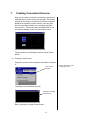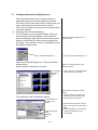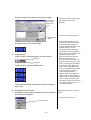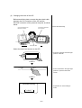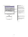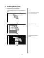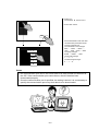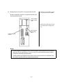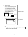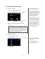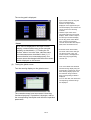
1
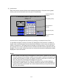
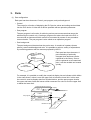
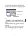
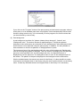
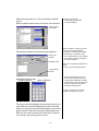
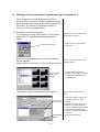
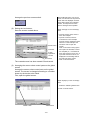
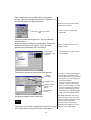
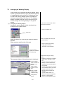
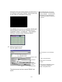
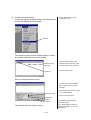
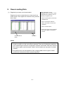
SCREEN CREATOR 5
User's Manual Vol. 1
SCREEN CREATOR 5
INTRODUCTION
■ Contents
1. Before Drawing Pictures
(1)
Outline of the advanced intelligent panel OIP .................................................................................. 1-1
(2)
Screen creation flow chart ............................................................................................................... 1-2
(3)
Installation ....................................................................................................................................... 1-3
• Development environment ................................................................................................. 1-3
• Starting installation ............................................................................................................ 1-3
• Specifying an installation directory .................................................................................... 1-4
2. Screens
(1)
Screen configuration ........................................................................................................................ 2-1
(2)
Global screen .................................................................................................................................. 2-3
(3)
Local screen .................................................................................................................................... 2-4
3. Parts
(1)
Part configuration ............................................................................................................................ 3-1
(2)
Control ............................................................................................................................................. 3-2
(3)
Part program ................................................................................................................................... 3-2
(4)
Part background .............................................................................................................................. 3-3
4. Basic Operations
(1)
Basic operations................................................................................................................................ 4-1
(2)
Basic tool bar ................................................................................................................................... 4-2
(3)
Convenient operation procedures .................................................................................................... 4-2
5. Screen Creator 5 Operations
(1)
Starting Screen Creator 5 ................................................................................................................ 5-1
(2)
Creating a project ............................................................................................................................ 5-1
(3)
Setting the project properties ........................................................................................................... 5-2
(4)
Restoring old model data
(5)
Exiting Screen Creator 5 ................................................................................................................. 5-4
(For reference) ..................................................................................... 5-3
6. Creating Simple Screens
(1)
Creating a new screen ..................................................................................................................... 6-1
6.1 Arranging Switches .................................................................................................................................. 6-2
(1)
Arranging a switch with a monitor lamp ........................................................................................... 6-2
(2)
Changing character of the name plate switch .................................................................................. 6-3
(3)
Changing the color of the switch with a monitor lamp ...................................................................... 6-5
6.2 Arranging Lamps ...................................................................................................................................... 6-6
(1)
Arranging an LED lamp ................................................................................................................... 6-6
(2)
Writing characters in the LED lamp ................................................................................................. 6-7
(3)
Changing the color of the LED lamp ................................................................................................ 6-8
6.3 Arranging Numerical Display .................................................................................................................. 6-10
(1)
Arranging numerical display .......................................................................................................... 6-10
(2)
Inputting character (Units) in numerical display ............................................................................. 6-11
(3)
Changing the size and number of digits of the numerical display .................................................. 6-12
6.4 Arranging Screen Select Parts ............................................................................................................... 6-14
(1)
Arranging a screen select switch ................................................................................................... 6-14
6.5 Saving Created Screens ........................................................................................................................ 6-15
(1)
Saving a local screen ...................................................................................................................... 6-15
7. Creating Convenient Screens
(1)
Creating a new screen ..................................................................................................................... 7-1
7.1 Creating a Numerical Setting Screen ....................................................................................................... 7-2
(1)
Arranging input numerical displays .................................................................................................. 7-2
(2)
Copying parts .................................................................................................................................. 7-3
(3)
Arranging the ten-key pad ............................................................................................................... 7-3
7.2 Changing a Screen from the Programmable Logic Controller PLC .......................................................... 7-5
(1)
Arranging a screen select switch ..................................................................................................... 7-5
(2)
Saving the local screen ................................................................................................................... 7-6
(3)
Arranging the screen select control parts on the global screen ....................................................... 7-6
7.3 Arranging an Alarm Display ..................................................................................................................... 7-8
(1)
Arranging an alarm display .............................................................................................................. 7-8
(2)
Saving the global screen ................................................................................................................. 7-9
(3)
Creating character strings ............................................................................................................. 7-10
8. Down-Loading Data
(1)
Registering a screen to be down-loaded ......................................................................................... 8-1
(2)
Changing the mode of the OIP ........................................................................................................ 8-2
(3)
Executing down-loading ................................................................................................................... 8-3
9. Preparing Screen Tests
(1)
Setting the OIP communication port ................................................................................................ 9-1
(2)
Setting the port of the PLC connected with the OIP ........................................................................ 9-3
(3)
Selecting the user mode .................................................................................................................. 9-4
10. Testing Created Screens
(1)
Testing the G1 screen ................................................................................................................... 10-1
(2)
Testing the G2 screen ................................................................................................................... 10-1
(3)
Testing the global screen .............................................................................................................. 10-2
INTRODUCTION
This "Introduction to Screen Creator 5" is an introduction to drawing
pictures using the KOYO Advanced Intelligent Panel GC5x Series.
The Advanced Intelligent Panel GC5x Series are programmable display
panels having highly advanced features, which are not wholly described
in this manual. This document is intended to introduce only the basic
operations of the versatile Screen Creator 5 features. For the features
and functions not shown in this document, refer to the operation
manuals.
PRECAUTION
We prepared this document with the greatest care. However, we will
not bear any responsibility to compensate you for any technical or
proofreading errors or omissions in this document or any indirect losses
or damages caused by using this document.
1. No part of this document may be reproduced in any form without
permission.
2. The features of Screen Creator 5 and this manual are subject to
change without notice.
3. We prepared this document with the greatest care. If you should
find any doubtful or erroneous descriptions or omissions, please
contact the Customer Support Desk of our Sales Department.
4. We will not bear any responsibility to compensate you for the results
of using Screen Creator 5.
5. This document does not warrant the exercise of the industrial
proprietary right or other rights or allow the exercising right. We will
not bear any responsibility for problems related to the industrial
proprietary right caused by the use of this document.
6. The copyright of this document is owned by KOYO. You must not
read out, analyze or disclose any contents.
7. If you have any questions about this document, please make inquiries
to:
Overseas Division
Koyo Electronics Industries Co.,Ltd.
Address: 1-171 Tenjin-cho, Kodaira, Tokyo 187 Japan
Telephone: 81-42-341-7711
Facsimile: 81-42-342-6871
Safety Precautions
Be sure to follow the safety precautions listed below in order to use the OIP safely. KOYO Ltd. cannot be
held liable for any damages incurred if these safety precautions are not followed.
WARNING
Design your system so that there are sufficient countermeasures for personnel
accidents and major equipment accidents. The system should have an external
protection and safety circuit, so that even if the OIP should malfunction or even
if there is a defect in the program the safety of the system is assured.
Do not use the touch panel of the OIP to make switches that are related to safety
or people or major damages (emergency safety switches, etc.). Be sure that the
system is designed so that it can cope with any errors or malfunctions in the
touch panel.
Be sure that Class 3 grounding is used for the protective-grounding terminal.
There is a possibility of electrical shock if the unit is not grounded.
If the OIP should malfunction, immediately turn off the poser and leave it alone.
If there is direct output to external output device such as PLCs, direct output will
be driven regardless of the ladder circuit interlock. Output may be used to drive
motors and the like, so avoid using direct output because it is dangerous.
CAUTION
Use and store the OIP in the environment described in the specifications
(regarding vibration, shock, temperature, humidity, etc.).
Do not use the OIP where it is subjected to inflammable or explosive gas, or
steam.
Before turning on the power, be sure that the power voltage rating of the OIP and
the voltage rating power supply match. Using a mistaken power supply can
damage the unit.
Do not disassemble or modify the OIP. Doing so can cause malfunctions and
lead to other problems.
The OIP touch panel is made of glass. Striking it with hard objects or pressing
hard on it may break the glass.
Do not push down on the OIP touch panel with mechanical pencils, screwdrivers,
or other sharp objects. Doing so can damage the touch panel or cause
malfunctions.
FOREWORD
1.
For Users of GC-SGP3
As GC-SGP3 is improved to Screen Creator 5, the operation
conditions are also changed. Pursuant to the change in the
operation environment into Windows 95, this manual uses the new
terms as shown below.
There are no differences in the concept of these terms.
GC-SGP3
Primitive
Figure registration
Setting
System
→
→
→
→
Screen Creator 5
Control
Texture
Property
Project
The user who understands the basic operations of GC-SGP3 may
begin with Chapter 3 "Parts" and will be able to run Screen Creator 5
free from troubles.
2. Terms Used in this Manual
This manual uses the following terms:
OIP:
The acronym of the Advanced Intelligent Panel.
PLC:
The acronym of the Programmable Logic Controller,
which is also called a sequence controller.
Link unit:
A communication unit for connecting the OIP with
the PLC. This manual designates such a communication
unit as a link unit or a computer link unit, though every
company uses its favorite designation.
Device: PLC's input and output relays, internal relays, timers,
counters, registers, etc. are generically called as devices.
3. Equipment Introduced in this Manual
This manual regards the OIP as the GC5x Series and the PLC as the
MELSEC AnA Series made by Mitsubishi Electric Corporation, and
assumes that the personal computer runs on Windows 95.
1. Before Drawing Pictures
(1) Outline of the advanced intelligent panel OIP
• The OIP is a programmable display panel with integrated touch switches. Different from
operation panels and control panels currently in use, the OIP has the following
features:
●
●
●
●
●
●
Compact design
Flexible adaptability to changes in specifications
Simple connection with the PLC with a single cable
Easy drawing by arranging a variety of parts
Versatile user interface features based on K-Basic
Simultaneous multi-channel serial port communication
With these features, the OIP is an intelligent operation panel of a new generation.
• Screens are created on the OIP GC5x Series using the exclusively designed drawing
tool Screen Creator 5 and down-loaded to channel 1 (RS-232C channel) of the OIP
through the RS-232C serial communication port of the personal computer using the
exclusive down-loading cable KDP01C1 (option). Screen Creator 5 is an advanced
exclusive drawing tool which runs on Windows 95 and allows the user to create various
screens only by arranging parts provided in various standard part libraries.
• The OIP features versatile communication methods.
It is capable of using up to three channels at a time and accordingly enables
simultaneous communication between the personal computer and the PLC.
● Direct access communication (with the PLC, etc.)
If the serial port of the OIP is connected with the CPU module port of the
PLC or the computer link module port, the OIP can read and write word/bit
devices of the PLC. The user need not take PLC's communication into
consideration particularly.
● Memory link communication (with a personal computer, etc.)
A personal computer sends data to the memory table in the OIP, and the OIP
displays it. The user can access the memory table from the screen and use
various PLC parts in the same manner as on the PLC.
● Host command communication (with a personal computer, etc.)
The personal computer uses the exclusive commands for communication
with the OIP. The user can send data in the same sense as the normal serial
communication between personal computers.
● Non-procedure communication (with a modem, controller, etc.)
The OIP can communicate with a device having an unchangeable
communication protocol such as a modem, temperature controller, etc. This
feature provides expanded system configuration.
1–1
(2) Screen creation flow chart
Screen Creator 5 creates screens in the sequence as shown below.
The operation procedures are described in details on the following pages. Follow the
procedures and create screens.
Starting Screen Creator 5
Creating a new project
End
Setting project properties
• Setting PLC
• Deciding OIP type
Debugging
Screen creation & editing
• Making background
• Arranging parts
• Setting link device
Trial operation
• Checking operation on
each screen
• Checking project
opera-tions
Down-loading
• Registration (Screen,
texture & character
strings)
• Setting up OIP
• Data transfer
Setting communication
parameters
• Setup on PLC
• Setting up OIP
Points
• It would be better to down-load data of each screen to check the screen operation
efficiently.
(Otherwise, data of all screens registered in the project including unnecessary data
are transferred at a time. The data transfer time will be longer.)
• It is possible to down-load screen data even though the next screen is not specified.
Though a warning message will appear on the screen, down-loading is enabled. If
the user attempts to change the screen into a screen which does not exist in the
OIP, the screen will not change.
1–2
(3) Installation
• Development environment
To use Screen Creator 5, a personal computer running on the Windows 95 operating
system. The recommended hardware requirements are as shown below:
① 256-color VGA monitor display or superior
② 16MB or more free memory space
③ 80MB or more free hard disk space
• Starting installation
Set the first floppy disk of Screen Creator 5 into the floppy disk drive of the personal
computer.
Select Windows 95 "Explorer" or "Specify name and execute" and execute
SETUP.EXE.
Example: When the floppy disk is set in the drive A
Specify the name and execute as shown below.
a:¥setup.exe
1–3
• Specifying an installation directory
When SETUP.EXE is executed, the setup window opens. Click on the Next button to
open the next window. Click on the Reference button to change the directory where
Screen Creator 5 is to be installed.
Browse button
Next button
In this window, click on "Next " button, and installation starts. Once installation has
started, follow the displayed messages and exchange the floppy disks one by one.
Now, the Screen Creator 5 world is open to you.
1–4
2. Screens
(1) Screen configuration
The OIP has two types of screens, which are
• Global screen (One screen for each project)
• Local screens
Actual screens are combinations of these two screens.
Local screen 3
Local screen 2
Global screen
Local screen 1
While the OIP is running, the global screen synthesized with a local screen is displayed.
When the local screen 1 is displayed on the OIP, for example, the global screen
synthesized with the local screen 1 is displayed (as shown below). The user looks at the
local screen 1 through the global screen, which can be compared to a transparent glass.
Synthetic display of the global screen and local screen
• Global screen
Each project has a single global screen. Screen Creator 5
automatically creates the global screen when the user intends to
create a new screen.
The following parts are arranged on the global screen:
a. Parts which are always needed for communication (such as
the warning display)
b. Parts which should always be displayed (such as the clock)
c. Common parts called from a lot of local screens (such as the
ten-key pad)
2–1
• Local screens
The local screens are created by the user and can be selected
on the connected external instrument such as the PLC or with the
switches on the screen.
The user can select the states of each part displayed on the screen: Normal (open), input
prohibited, half tone, and closed. The pattern of a part in the "Normal (open)" state can be
seen. The pattern of a part in the "Closed" state cannot be seen. While the OIP is running,
the user can change the open and closed states of only parts of the "movable" properties.
Take, as an example, the part property of the ten-key pad. When the ten-key pad is called
by another part or external instrument, its "Closed" state changed into the normal state.
Thus, it should be arranged in the closed state on the screen.
Movable property
Part state property
If a part should be arranged in the closed state, it is necessary to check off the
"Removable" box of the part. Only parts of the movable properties can be opened or
closed.
It is possible to overlay movable parts on the screen. On the contrary, it is impossible to
overlay immotive (fixed) parts.
Points
• When open parts are overlaid, they have hierarchical relationship. The lower-order
part is disabled from display refreshing and switch input.
• A newly opened part is higher than older parts. Parts displayed on the global screen
are always higher than the parts on the local screens.
2–2
(2) Global screen
Parts on the global screen are
always displayed even when the
local screen is changed. Thus,
arrange such parts so that they
will not obstacle the local screen.
8
It is possible to arrange parts in
the closed state and open them
whenever necessary. "Movable"
parts can only be arranged on
the global screen.
Points
• Only parts can be arranged on the global screen. Draw patterns on the local
screens.
• Parts arranged on the global screen are always displayed on the screen.
• Communication between the PLC and OIP is enabled on the currently displayed
local screen or global screen only. Thus, arrange parts which are always needed for
communication on the global screen.
2–3
(3) Local screen
Each local screen consists of parts on the background pattern. Like parts on the global
screen, parts on local screens are in the open or closed state.
Screen background
Processed data registration
(Step 3)
(Pattern)
Part (Analog meter)
Part (Numerical
display)
Part (Ten-key pad)
Part (Screen select
switch)
A local screen is changed with the switch or by issuing a command from the PLC.
It is possible to display a variety of screens by changing the local screens. In addition, a
single screen can demonstrate various features as the parts on the screen are opened or
closed. A maximum of 1024 parts can be arranged on a single screen. If too much parts
are arranged on a screen, the OIP bears an excessive load and smooth operation may be
disabled. In such a case, divide the screen into several sub-screens to decrease the parts
displayed on each sub-screen.
Points
• Both a pattern and parts may be arranged on a local screen. A pattern is also called
a screen background and always resides below the parts. If parts are arranged in the
position where a pattern is drawn, the pattern is hidden by the parts. In such a case,
draw the pattern as the background displayed in the parts.
• Communication between the PLC and OIP is enabled on the currently displayed
local screen or global screen only. Allocate continuous devices as far as possible. If
continuous devices are allocated, the communication efficiency is improved and the
OIP runs more quickly.
2–4
3. Parts
(1) Part configuration
Each part has three elements: Control, part program, and part background.
• Control
The control is a function of displaying the PLC device values and writing touched data
into the PLC device. It links with a device specified with an operation parameter.
• Part program
The part program is a function of achieving various part movements that cannot be
achieved by the control only. Creating a program can reduce the load to the PLC or
connect with an instrument which cannot be connected by means of non-procedure
communication. The part program is also called as an operation program.
• Part background
The part background denotes how the part is seen. It consists of a pattern (drawn
picture), texture and background color. It is possible to select a variety of expressions
by combining patterns with the textures prepared by KOYO.
Each part has three elements. A
part consisting of optionally
changed three elements can be
registered in the library. Once a
part is registered as a customized
part, it can be recalled and reused
quickly.
Part background
- Pattern
- Texture
- Background color
Part program
(K-Basic)
Control
(Function itself)
For example, it is possible to modify the numerical display into an indicator which blinks
in the case where a value is over the upper limit or below the lower limit. In this case,
the control is used to display data from a linked device, and the part program checks
the upper and lower limits and issues a blink command if a value is over the upper limit
or below the lower limit.
Numerical indicator (Control)
Display
80.1
Data from the linked device
Pattern
Part program
Texture
Blink command
Background color
Part background
Movement of part
conf
end conf
event
end evnt
3–1
(2) Control
Controls can be directly linked with a PLC device. Thus, it is possible to display directly
the value of the PLC device by specifying the name of a device to be linked using the
"arranged part property" operation parameter. Control setting is enabled by opening
"Detailed edit" of the control. Some items cannot be set. Change such items by means of
editing the contents of the part. To display using the operation program, invalidate the
operation parameter in the control property setting procedure.
Operation parameter of the
numerical display control
Device to be linked
Program (P) button
Detailed edit (D) button
Points
• It is possible to add controls to a part in the part contents editing procedure. By
validating the operation parameter using the control property, the control operation
parameter appears in the part property. If the name of a device to be linked is
specified, display from the PLC device or writing into the device is enabled.
(3) Part program
Part programs allow a variety of screen controls including opening and closing parts,
communication, etc. As a matter of course, part programs also enable data display in
controls, blinking selection, input with switches, etc. Some standard parts contain
operation programs.
Click on the "Program" button, and the editor starts. Using the editor, it is possible to
change operation programs written in K-Basic. The operation programs of the standard
parts can be changed. Note that, however, operation may become faulty or data
down-load may be disabled if the operation programs of the standard parts are changed.
For details of writing operation programs, refer to the separate "Writing K-Basic
Programs".
3–2
If you click on the "Program" button of the part property and activate the program editor to
check parts, a lot of standard parts have no programs. Such standard parts achieve their
functions using controls only. It is unnecessary to write programs for such functions that
can be achieved by controls only.
(4) Part background
A part background consists of a "pattern (drawn picture element)", "texture" and
"background color". The texture denotes a registered figure. Though the optimum
background color and texture are selected for each standard part, other background color
and/or texture can be selected using the part property. In addition, it is also possible to
write characters or the like as patterns or change patterns of parts.
The lowermost layer of the part background is the color of the background. Background
color is set using the property of that part. This is a function of painting over the specified
part area in the specified color. On the background color, the specified texture is
displayed all over the part area. The background color is seen in the transparent part of
the texture. The pattern of the part is displayed on the background color and texture.
Like the standard parts, the textures are stored in the library. It is also possible to create
new textures and register them in the library using the new creation function on the library
menu. Create any intended textures and register them in the library if it is necessary.
3–3
4. Basic Operations
This section describes the basic operations needed to start Screen Creator 5.
(1) Basic operations
• Clicking and double-clicking the mouse buttons
The mouse buttons are clicked or double-clicked for "icon selection", "validation of
selected functions", "short-cut" and other operations.
Clicking the left button
Double-clicking the left button
Clicking the right button
(Selection, etc.)
(Selection, validation, etc.)
(Short-cut menu or cancellation)
Press the left button once.
Press the left button twice quickly.
Press the right button once.
• ESC key
Pressing the ESC key cancels selected functions one by one.
4–1
(2) Basic tool bar
Screen Creator 5 has a tool bar used for the basic operations. If no tool bar is displayed,
select "Display" on the "Tool" menu.
It is possible to cut the tool bar off the edge of the window and move it to the center of the
window. Such a tool bar is used as the tool box. Use the tool bar as you like.
Standard tool bar
The standard tool bar has icons for selecting basic operations including writing and
reading files, copying, pasting, etc.
Drawing tool bar
Selection
Drawing
selection
Part selection
Control
selection
The drawing tool bar has icons for arranging patterns and so forth on the screens and
parts. The four icons at the left side of the tool bar are used to select the types of objects
to be selected in the window. Patterns (drawing elements) and parts are overlaid on the
screen and it may be hard to select an intended object. In such a case, select the object
type with one of these buttons to limit the selection objects.
Part tool bar
The part tool bar has icons for the parts to be arranged on the screen. A part selection
window corresponding to the pattern is displayed. See the pattern and select parts.
(3) Convenient operation procedures
• SHIFT key
Hold the SHIFT key while moving the mouse to draw a vertical or vertical line forcedly.
• ↑, ↓, → and ← keys
Press one of these keys to move the cursor in the direction marked on the key, instead
of using the mouse.
• Q key
While drawing a picture, press the Q key to move the cursor to the end or center of the
nearest figure or control.
4–2
5. Screen Creator 5 Operations
This section describes the actual screen creation procedures, taking an example of creating a
new project named "DEMO" as an examination project.
(1) Starting Screen Creator 5
When Screen Creator 5 has been installed properly, the shortcut icon appears in the
Windows 95 screen. Double-click on this icon, and Screen Creator 5 starts up.
Short-cut icon
(2) Creating a project
A project means aggregate screen data on a single global screen and one or more local
screens as well as setting. It is a set of screens to be down-loaded to the OIP. Select
"New (N)" on "Project (P)" menu.
New project creation
To edit an existing project, select "Open" to open it. Screen Creator 5 memorizes the
previously used project by default. If you use the same project, proceed with operation.
Then, carry out necessary setting of the project.
5–1
(3) Setting project properties
Set the properties of a project as shown below.
Comment
a. Input the name of the intended
project.
b. Input a comment for the project.
OIP model
c. Select an OIP model to be used.
Global
screen
name
d. Leave the global screen name as
is "DEMO".
Project name
Others need not be changed.
Select the model of a PLC to be connected.
Page selection
PLC
selection
OK button
e. Change the page to select
connected instrument(s).
f. Carry out setting of connected
instrument(s).
Select MITSUBISHI (AnA/AnU)
(LINK) (High-speed). If other
instruments are to be connected,
specify them here in advance.
Since up to three channels can be
connected with the OIP, it is
possible to select up to three
items.
g. Click on the OK button.
The project setting is completed.
5–2
(4) Restoring data of old model (For reference)
Screen Creator 5 can read screens created on
GC-SGP3 and down-load them to the GC5x Series. It
converts data "backed up" in the "File Operation" mode
of GC-SGP3 into Screen Creator 5 data.
System name
Select button
Confirmation
button
New project
name
Execute
button
5–3
Use GC-SGP3 data as shown below.
Select old model data restoration on
the tool menu.
a. Input the system name of
backed-up GCx Series data. It can
be selected with the Select (S)
button.
b. Make sure that the system file
exists in the specified folder.
c. Input a new project name.
Leave other settings unchanged.
d. Click on the Execute (E) button.
(5) Exiting Screen Creator 5
Select "Exit Application" on the "Screen" menu or click on the Close (
Point
• Exit Screen Creator 5 after the screen has been saved.
5–4
) button.
7.
Creating Convenient Screens
Now, try to create a screen for exercising copying and
setting numeric values on the ten-key pad. The screen
created in this section consists of only three numerical
displays for inputting numeric values, a ten-key pad,
and a screen select switch for controlling operation
from the PLC. This section also describes how to use
the warning display used for monitoring error bits.
The procedures of creating the screen are as shown
below.
(1) Creating a new screen
Prepare a screen to be created as described in Chapter
6.
New screen
creation
The base of a new screen is made.
Window for creating
a new screen
Now, you begin to create a new screen.
7–1
a. Select "New (N)" on the
“Screen(S)” menu.
7.1 Creating a Numerical Setting Screen
This section describes how to create a screen for
writing data input from a ten-key pad into a specific
PLC device. Every time data is input on this screen, the
cursor advances from one item to the next item.
This screen consists of a ten-key pad and several input
numerical displays.
(1) Arranging input numerical displays
Try to arrange an input numerical display. When you
touch the input numerical display, a ten-key pad is
opened (displayed). Data input from the ten-key pad is
written in a specified PLC device and is displayed on
the screen. As a matter of course, it is possible to input
and display double words.
Numerical display icon
Select the numerical display icon. The part selection
window opens.
Select a pattern and function of a part.
Input numerical
display to be
selected
The properties of the selected part appear.
Input the name of
a device to be
linked.
Input the next part
name.
Template
9-16
7–2
Select the numerical display icon in
the part tool box.
a. Click on the numerical display icon.
Select a necessary part in the part
selection window.
b. Click on the input numerical display
"#CLN2002", in this example.
Set the data of the input numerical
display.
c. Input the name of a device to be
linked with the numerical display.
Input D300 in this example.
d. Input the next part name, which is
B001, since the name of this part is
B000.
e. Select "template 9-16" and set the
operation parameters on the
second page.
Set the operation parameters on the second page.
Input the part
name of the
ten-key pad.
Arrangement
button
Arrange the input numerical display.
(2) Copying parts
Copy the input numerical display as shown below.
Copy icon
Paste icon
Copy the input numerical display twice.
Three input numerical displays have been arranged on
the screen.
(3) Arranging the ten-key pad
Arrange the ten-key pad corresponding to the arranged
input numerical displays.
f. Input the part name of the ten-key
pad, which is "TNK" in this
example.
g. Click on the Arrangement button.
h. Click the Mouse button once on
the screen, and the frame of this
numerical display is displayed.
Click the Mouse button again at an
intended position, and the
numerical display is arranged at
that position. Since the numerical
display has a switch function, it can
only be moved by 20 dots.
i. Click on to select the arranged
part. Click on the copy icon.
j. Click on the paste icon, then. The
property window of the copy parts
opens. Input the part name "B001",
next item part name "B002", and
device name to be linked "D301".
Click on the "Arrangement" button
to arrange the parts. Now, the
copied parts are arranged.
k. Likewise, click on the paste icon
again to open the part property
window again. Input the part name
"B002". Leave the next item part
name blank. Input the device name
to be linked "D302". Click on the
"Arrangement" button.
Select the input part icon in the part
tool box.
l. Click on the input part icon.
Input part icon
7–3
Select the input part icon. The part selection window
opens.
Select a pattern and function of the part in the window.
m. Select a ten-key pad
corresponding to the input
numerical displays.
Ten-key pad to
be selected
The property window of the selected part appears.
"Close" part
condition
Set the conditions of the ten-key pad
for the input numerical displays.
n. Select the "Closed" part condition.
o. Check off the "Movable" check
box. Unless this box is not checked
off, the part cannot be arranged in
the closed condition.
Movability check
There are no operation parameters to
be set.
p. Click on the Arrangement button.
Arrangement
button
Arrange the ten-key pad.
Closed condition
(Open condition)
q. Click the Mouse button once on
the screen, and the frame of the
ten-key pad is displayed. Click the
Mouse button again at an intended
position, and the ten-key pad is
arranged at that position.
If a part is arranged in the closed
condition, its frame only is seen.
The input numerical displays and the ten-key pad to be
used with the numerical displays have been arranged.
When you touch an input numerical display, the ten-key
pad is opened. When you input data and pressing the
ENT key, the cursor moves to the next item. If there is
no next item, the ten-key pad is closed.
7–4
7.2 Changing a Screen from the Programmable Logic Controller PLC
Try to change the screens according to the PLC's
specified device numbers. It is also possible to change
the screens with the screen select switch displayed on
the screen. The number of a displayed screen is
informed of PLC's specified device.
(1) Arranging a screen select switch
Try to arrange a screen select switch. You can write a
new screen in a specified device by pressing this
switch.
Screen select part icon
Select the screen select part icon. The part selection
window appears.
Select a pattern and function of the part in this window.
Previous screen
switch to be
selected
The property window of the selected part appears.
Select the icon of the screen select
part in the part tool box.
a. Click on the icon of the screen
select part.
Select a necessary part in the part
selection window.
b. In this example, click on the
previous screen switch "CLB2003"
in the screen select switches (of
notification type).
Set data of the previous screen
switch.
c. Input a next screen name on the
template, which is G1 in this
Input a next
example.
screen name.
d. Input the name of a device to be
linked (i.e., a device which the
screen number is to be informed),
which is D500 in this example.
e. Set the screen select control part
to "Use: 1".
f.
Click
on the OK button.
Arrangement
button
7–5
Click the Mouse button once on the
screen, and the frame of the previous
screen switch is displayed. Click the
Mouse button again at an intended
position, and the previous screen
switch is arranged at that position.
Arrange the previous screen switch.
(2) Saving the local screen
Save the screen created above.
Option
Select "Save(S)" on the “Screen(S)”
menu.
g. Input the screen name, which is
G2 in this example.
h. Input the comment, which is
"Introduction" in this example.
i. Input the screen registration name,
which is 2 in this example. This
number is used to open the
Screen name
screen.
j. Click on the screen saving option.
Comment
If this option is activated, screens
are compiled (i.e., converted into
Screen
down-load screens) one by one. If
registration
input data contains an error, it is
number
displayed in the message field in
the lower part of the screen.
Save button
k. Click on the Save button.
The created screen has been named G2 and saved.
(3) Arranging the screen select control parts on the global
screen
Arrange the screen select control parts on the global
screen. The screen is changed according to a number
shown by the device to be linked.
First, open the global screen.
Select "Open(O)" on the “Screen(S)”
menu.
l. Select the "DEMO" global screen.
m. Click on the OK button.
OK button
Global screen
7–6
Then, arrange the screen select part on the global
screen. This part changes the screen into a screen of a
number indicated by a specified device.
Select the icon of the screen select
part in the part tool box.
Screen icon select
part
Select the screen select part icon. The part selection
window opens.
Select a function of the part in the window. The screen
select control part has no pattern. There are other
special control parts that have no patterns.
Screen select
control part to be
selected
The property window of the selected part appears.
"Close"
condition
Movability check
Input the name of
a device to be
linked.
Arrangement
button
Arrange the screen select control part.
The screen can be now changed from the PLC or using
the screen select control part and the screen select
7–7
n. Click on the icon of the screen
select part.
Select a necessary part in the part
selection window.
o. Click on the screen select control
part "#CLB301".
p. Select the "Closed" part condition.
q. Check off the "Movable" check
box. Unless this box is not checked
off, the part cannot be arranged in
the closed condition.
r. Input the name of a device to be
linked (i.e., screen select control
device). In this example, it is D500,
which is the same as the name of
the device linked with the screen
select switch (of notification type).
s. Click on the Arrangement button.
Click the Mouse button once on the
screen, and the frame of the screen
select control part is displayed. Click
the Mouse button again at an
intended position, and the part is
arranged at that position. Be sure to
arrange it on the global screen.
7.3 Arranging an Warning Display
In this section, try to arrange an warning display, which
checks a specified number of error bits at the beginning
of a specified bit device of the PLC. When there is an
error bit, this warning display opens and displays a
warning corresponding to the error bit. The warning
display is closed when the error bit is turned off. Be
sure to arrange the warning display on the global
screen.
Select the icon of the screen select
(1) Arranging an warning display
part in the part tool box.
Arrange an warning display, which should also be
arranged on the global screen.
a. Click on the alarm icon.
Alarm icon
Select the alarm icon, and the part selection window
appears.
Select a pattern and function of the part.
Select a necessary part in the part
selection window.
b. Click on the list type warning
display (for bit devices)
"#CLA2001" in this example.
List type warning
display to be selected
(for bit devices)
The property window of the selected part is displayed.
Close condition
Input the name of
a device to be
linked.
Input the total
number of error
bits.
Input the initial
number of the
character string.
Arrangement
button
7–8
Set data of the list type warning
display.
c. Select the "Closed" part condition.
Check off the "Movable" check
box.
d. Input the name of a device to be
linked (i.e., device name at the
initial alarm bit), which is M500 in
this example.
e. Input the total number of error bits
to be checked, which is 10 in this
example. By this, error bits
between M500 and M509 are
checked.
f. Input the initial number of a
character string to be registered,
which is 1 in this example.
g. Click on the Arrangement button.
Arrange the list type warning display (for bit devices). It
is arranged in the closed condition, and its frame only
is seen when it is arranged on the screen.
Click the Mouse button once on the
screen, and the frame of this warning
display is displayed. Click the Mouse
button again at an intended position,
and the warning display is arranged at
that position.
If the M500 bit is turned on, for example, this list type
warning display opens and the character string of
registration number 1 is displayed. The method of
creating a character string is described below.
(2) Saving the global screen
Save the global screen.
Select "Save(S)" on the “Screen(S)”
menu.
Screen name
h. Click on the Save button.
Comment
Screen
registration
number
Option
Save button
The global screen has been named "DEMO" and
saved.
7–9
"Global screen" is the default
comment.
Do not input any registration number.
It is unnecessary to register the
number of the global screen.
i. Select “New Text(S)” on the
(3) Creating character strings
“Project(P)” menu.
Create and register character strings to be displayed on
the warning display as shown below.
New Text
The character string creation window appears. Create
an intended character string in the window.
Character string
input area
j. Input a character string in the
character string input area. Input
"Pressure drop" in this example.
k. Click on the save icon.
Save icon
Save the created character string.
l. Input the name of the character
string, which is "MOJI1" in this
example.
m. Input a registration number, which
is “1” in this example.
Character string
n. Click on the Save button.
Registration
number
Save button
The created character string is saved.
7–10
One character string has been
created and saved.
Try to create character strings of
registration numbers 1 to 10 in the
same manner.
8. Down-Loading Data
(1) Registering a screen to be down-loaded
Register the screen created above to down-load it as
shown below. Also register the character string created
above here.
Select "Register(R)" on the
“Project(P)” menu. If a screen number
has already been registered, it is not
necessary to register it here.
a. Click on a free space in the screen
registration list.
b. Click on the Screen reference
button, and select a screen to be
registered.
c. Click on the OK button.
d. If there is a texture to be registered
and used, register it in the same
manner.
Screen reference
button
OK button
Points
• Be sure to register a screen in registration number 1. It is displayed first when the
power is turned on or the user mode is selected. There are no particular restrictions
upon numbering the screens of registration numbers 2 and after. Note that, however,
the memory space used increases a little if serial numbers are not given to created
screens.
• No global screen can be registered. Only a single global screen is given to each
project and is determined by the project properties.
8–1
(2) Changing the mode of the OIP
Before transferring data, connect the down-load cable
between the CH1 connector of the OIP and the
RS-232C connector of the personal computer as shown
below.
Connect the cable firmly.
Connect the cable to the
RS-232C connector.
Connect the cable to the
CH1 connector.
Lap-top PC
AIP
OIP
Down-load cable
Select the down-load screen on the OIP.
a. Press the upper left and lower right
position of the OIP.
<<OIP>>
▼
ダウンロード
Download
ユーザモード
User
Mode
b. Press "Download" in the upper right
position to open the down-load
screen.
<<OIP>>
▼
Download Executing
ダウンロード実行中
c. Preparation for down-loading is
made.
Cancel
キャンセル
8–2
Select "Download(D)" on the
“Project(P)” menu.
(3) Executing down-loading
a. Select the RS-232C port of the
personal computer as the
down-load port according to the
setting of the personal computer.
COM1 is selected in this example.
Down-load port
selection
b. Click on “Build”. If the operation
parameters on the parts displayed
Transmit button
on the screen contain errors, a
syntax error may occur.
Build button
c. On completion of operation, click
on "Transmit".
<<Screen Creator 5>>
▼
“Build->Transmit” are executed
continuously by clicking on Create and
Transfer.
Download was Successful
ダウンロード 終了
d. When down-loading is completed,
"Download was successful" is
displayed on the OIP.
<<OIP>>
8–3
9. Preparing Screen Tests
(1) Setting the OIP communication port
Carry out setting so that the PLC is connected with
CH1.
a. Press "System setup" in the upper
left corner of the OIP screen.
System
Setup
システム設定
システムチェック
System
Check
▼
b. Press "RS-232C-1 Setup".
RS232C-1
RS-232c-1設定
Setup
RS232C-2
RS-232c-2設定
Setup
RS485
RS-485設定
Setup
▼
Connected
通信種別
Device
c. Press the frame of Connected
Device.
Not
Used
未使用
Communication
通信速度
Rate
9600
Parity Check
パリティ
NONE
ストップビStop
ットBit
1
Data
Length
デ
ータ長
8
bps
▼
9–1
d. Select PLC.
The asterisk, ★, moves to PLC.
Not
Used
未使用
PLC
★ PLC
プリンター
Printer
バーコード
Bar
Cord R
磁気カード
テンキー
Ten
Key
ICカード
Memory Card
ホスト
Host
e. Press “ENT” button.
bps
Multi-panel Unit
設定終了
ENT
④
⑤
Connected
通信種別
PLC
Device
Communicatio
通信速度
n 9600
パリティ
Parity
Check
ストップStop
ビット
Bit
データ長
Data
Length
f. Set the transmission rate and other
communication parameters equal
to those of the link unit.
• The transmission rate changes
9600 → 19200 → 38400 →
1200 → 2400 →4800 → 9600.
• The parity changes
EVEN → NONE → ODD.
• The stop bit changes
1 → 2 → 1.
• The data length changes
8 → 7 → 8.
bps
NONE
1
8
Points
• No communication port can be set unless data to be down-loaded is transferred to
the OIP. If the communication port cannot be set, check if data has been
down-loaded properly.
• Once the communication port is specified, the setting is stored. It is unnecessary to
specify the communication port every time data is to be down-loaded.
Data
9–2
(2) Setting the port of the PLC connected with the OIP
g. Select the communication mode of
the computer link unit to FORM4.
Set the conditions of the PLC computer link unit to be
connected with the OIP.
Communication
status indicator
LED
h. Specify the communication format
and number of the computer link
unit.
Format setting DIP
switches
Communication
mode setting
switch
Points
• Communication is disabled if some communication format parameters are different
from the OIP port parameters. In such a case, the communication status indicator
LED blinks. Recheck the parameters.
• Communication is disabled if the number of the computer link unit is different from
the number specified with the operation parameter.
9–3
(3) Selecting the user mode
Since screen data has been transferred to the OIP,
connect the OIP with the PLC and carry out trial
running.
The OIP is connected with the PLC through the
computer link unit, in principle. Also set the
communication format in the case where the OIP is
directly coupled with the CPU module. The RS-232C or
RS-422 (RS-485) port is used for connection. In this
screen test, use the RS-232C CH1 port.
RS-232C cable (prepared by the user)
i. Connect the communication cable,
which should be prepared by the
user. To connect with the CPU
directly, use the optional direct
connection cable.
Computer link unit
Mitsubishi AnA PLC
AIP
OIP
When the power is turned on, the user mode is
automatically selected and this operation is needless.
Download
ダウンロード
j. Press "UserMode" to start
operation.
User Mode
ユーザモード
Points
• If it takes a long time until the first screen is displayed when entering the user mode,
the OIP may communicate with the PLC improperly. Check if the communication
parameters are specified properly in such a case.
9–4
10. Testing Created Screens
When the OIP enters the user mode,
the G1 screen is displayed first.
(1) Testing the G1 screen
Try to test the screens created above.
Lamp
Numerical
display
a. Try to test the switch with a monitor
lamp. Touch the switch, and check
if the lamp of the switch goes on.
In addition, check if the value of
M100 is turned on only when the
switch is touched using the
programming console unit.
b. Test the lamp. Turn on the M200
bit using the programming console
unit. Make sure that the lamp goes
on when the M200 bit is turned on.
Lamp switch
Screen select
switch
Check to see if this screen functions properly.
Points
c. Test the numerical display. Make
sure that 0 is displayed now. Input
any value to D100 using the
programming console unit. Check
if the input value is displayed on
the numerical display.
If no value is displayed on the numerical display,
communication may not be executed properly. If
the SD and RD lamps on the computer link unit
flash quickly, communication is executed. If they
flash only occasionally, some communication
parameters may be set incorrectly.
(2) Testing the G2 screen
Then, try to test the G2 screen.
Input numerical display
Ten-key pad
d. Touch the screen select switch.
Check if the screen changes into
the G2 screen.
e. Touch the uppermost input
numerical display, and check if the
ten-key pad is opened.
Screen select switch
10–1
The ten-key pad is displayed.
f. Input a value on the ten-key pad,
then touch the ENT key.
Check if the input value is
displayed on the uppermost input
numerical display. Also check if the
cursor moves to the following
indicator.
g. Likewise, input values in the
second and third input numerical
displays. When a value is input in
the third input numerical display,
the ten-key pad is closed. Make
sure, using the programming
console unit, that the value input to
D300, D301 and D302 are set.
Points
If no value is displayed on this input numeric
display, communication may not be executed
properly as described in (1) “Testing the G1
screen” above. In such a case, take the same
countermeasures as described in item (1). If
communication is not executed properly, the
screen cannot be changed with the screen select
switch displayed on this screen.
h. Press the screen select switch,
and check if the screen changes
into the G1 screen. Then, the
screen number 1 is displayed on
D500 using the programming
console unit.
(3) Testing the global screen
Test the warning display on the global screen.
The created screens have been tested. Have they
functioned properly? If operation is improper, refer to
the corresponding description and check the operation
parameters.
10–2
i. Turn on the M500 error bit linked
with the warning display using the
programming console unit. Check
if the warning display opens and
the character string "Pressure
Drop" corresponding to M500 is
displayed.
Turn on other bits, and check if the
corresponding character strings
are displayed.
You may have questions even if you have read this "Screen Creator 5 Operation Manual:
Introduction" carefully. In such a case, contact KOMATSU Customer Support Group by
telephone or facsimile.
KOMATSU
Sales Department Customer Support Group
Electronic System & Component Dept.
Electronics Div.
Address:
Telephone:
Facsimile:
Business hours:
4-20-1 Kamata, Ota-ku, Tokyo 144 JAPAN
03-5711-1838
03-5711-1840
9:00 AM to 6:00 PM (Monday to Friday)
KOMATSU
Service Group
Electronic System & Component Dept.
Electronics Div.
Address:
Telephone:
2597 Shinomiya, Hiratsuka-shi, Kanagawa Prefecture, 254 JAPAN
0463-22-8431