1
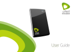
Wireless DIY
security alarm
starter kit
User guide
E0166_Wireless_Security_Alarm_Kit_Prod_Manual_PM1004a_R1.indd 1
27/02/2015 4:24 pm
2
Features
1
Introduction 3
1.1 Box Content 3
1.2Features 3
1.3Recommendations 4
1.4Warnings 4
2
Easy Install 5
2.1 Insert SIM card into the alarm panel and install in desired location 5
2.2 Register accessories with the alarm panel 6
2.3 Download App and set your personal alarm settings 7
3
Alarm settings 8
3.1 Enter Setup Mode 8
3.2 Exit Setup Mode 8
3.3 Store phone numbers 8
3.4 Delete phone numbers 9
3.5 Change password 9
3.6 Set Siren volume 9
3.7 Set Siren ring time 9
3.8 Set Entry and Exit delay 9
3.9 Clear connected sensors 9
4
Control your alarm 10
4.1 Arm your system 10
4.2 Disarm your system 10
4.3 Home mode 10
4.4 Mute mode 10
4.5 Emergency mode 10
4.6 Make a phone call 11
4.7 Speed Dial 11
4.8 Remotely control your alarm 11
5
Responding to an alarm 12
6
Specifications 13
6.1 Alarm panel 13
6.2 Wireless remote 16
6.3 Wireless motion sensor 17
6.4 Wireless door/window sensor 20
6.5 RFID Tag 22
6.6 SMS operation 23
6.7 Assign sensors to zones 28
7
FAQ 30
E0166_Wireless_Security_Alarm_Kit_Prod_Manual_PM1004a_R1.indd 2
Than
Wirel
Pleas
the b
this m
1
I
1.1 B
1 x A
2 x R
1 x W
1 x W
2 x R
1 x A
2 x 8
(8
2xS
NOT
own
27/02/2015 4:24 pm
3
3
3
4
4
5
5
6
7
8
8
8
8
9
9
9
9
9
9
10
10
10
10
10
10
11
11
11
12
13
13
16
17
20
22
23
28
30
1. Introduction
Thank you for purchasing the Hills
Wireless Security Alarm DIY Starter Kit.
Please read this manual carefully to get
the best use out of this product. Keep
this manual for future reference.
1
Introduction
1.1 Box Content
1 x Alarm Panel (with internal siren)
2 x Remote Controls
1 x Wireless Motion Sensor
1 x Wireless Window/Door Sensor
2 x RFID Tags
3
1.2Features
•
Wireless alarm system
•
Easy to install
•
Remote access control via phone
•Supports up to 50 wireless sensors
and associated accessories
•Easy registration of new
accessories
•Built-in 120dB siren to deter
potential intruders
•Store up to 5 phone numbers and
5 SMS numbers
•Arm, disarm and monitor remotely
via phone
1 x AC Adaptor
2 x 800 mAh Batteries
(8hr in standby mode)
2 x Security Warning Stickers
NOTE: You will need to supply your
own SIM card for use with this system
E0166_Wireless_Security_Alarm_Kit_Prod_Manual_PM1004a_R1.indd 3
27/02/2015 4:24 pm
4
1. Introduction
1.3 Recommendations
1.4 Warnings
2 Eas
For your safety, it is recommended to
follow these precautions:
•The alarm panel is provided with a
separate battery. Please dispose the
used batteries responsibly.
2.1I
a
d
•Do not open the case of the alarm
panel and do not repair it yourself.
Your
3G n
card
•Do not forget to arm the alarm panel
during your absence and make sure
it works properly.
•Do not forget to lock the doors,
windows and other exits.
•Always keep your remote control
with you and do not leave it visible
or noticeable.
•To optimize the operation of the
alarm system, it is recommended to
carefully select the location for each
accessory to be installed.
•It is recommended to mount the
sensors on a smooth wall, to ensure
the proper use of the tamper switch.
•Accessories purchased separately
must be connected to the alarm
panel manually.
•Wait until the end of the auto-test
before replacing the cover of the
sensor.
•If you encounter an issue with the
product, contact your supplier or an
authorised technician.
•Take care of this product and do not
let water get into it as it may damage
the product.
•Place the alarm panel in a cool, dry
and well-ventilated area. Do not
install sensors near heating, cooling,
or ventilation.
•Do not use detergent or other
flammable materials to clean
this unit.
SIML
mobi
card
1.I
i
i
2.I
d
3.P
s
4.S
•Do not let your device fall on the
floor.
•Remove the battery holder cover
with care.
•If you do not use this product for a
long time, remove the batteries to
optimize their lifespan.
•Do not cross the beams of different
motion sensors.
E0166_Wireless_Security_Alarm_Kit_Prod_Manual_PM1004a_R1.indd 4
27/02/2015 4:24 pm
2. Easy Install
5
2 Easy Install
a
the
2.1Insert SIM card into the
alarm panel and install in
desired location
m
lf.
Your SIM card must support the 2G or
3G network (850/2100Mhz ). The SIM
card should have SIMLOCK deactivated.
e
r an
not
mage
dry
ing,
SIM
SIMLOCK can be deactivated using a
mobile phone prior to installing the SIM
card into your alarm panel.
1.Insert the SIM card (NOT included)
in the alarm panel as shown in the
image below.
2.Install your alarm panel to your
desired location
3.Plug the adaptor into an AC power
socket.
4.Switch the alarm panel on.
r
E0166_Wireless_Security_Alarm_Kit_Prod_Manual_PM1004a_R1.indd 5
27/02/2015 4:24 pm
6
2. Easy Install
2.2Register accessories with the
alarm panel
2.3D
p
Remote Controls, Motion Sensors,
Window/Door Sensors, RFID Tags and
additional sirens must all be registered
with the Alarm Panel prior to use.
Remo
and c
be pe
using
This a
Store
To register each accessory, you must
first enter Registration Mode on the
Alarm Panel.
To ins
searc
App”
pass
will b
1. On the Alarm Panel, press “#1”
2.The Connection LED indicator
will light up to indicate
connection mode.
Once
icon
throu
yours
syste
mobi
in you
Trigger connection on the accessory
you wish to register via the correct
method below:
Accessory
Trigger
Wireless remote control
Press any button on the remote control.
Wireless motion sensor
Press the connect button at the back of the
sensor or trigger the sensor by moving in front
of it.
Wireless window/door sensor
Separate the magnet from the transmitter
RFID Tag
Swipe the RFID tag in front of the RFID reader
on the alarm panel
Additional siren
Contact Hills Security for further information
Once you have registered all
accessories, exit Registration Mode:
1.Press the “Disarm” key on the
alarm panel
NOT
the a
a pho
Only
contr
sectio
Accessories may now be installed
following specifications in section 6 of
this document.
Additional accessories not listed above
may be registered. Consult the relevant
accessory manual for trigger details.
E0166_Wireless_Security_Alarm_Kit_Prod_Manual_PM1004a_R1.indd 6
27/02/2015 4:24 pm
nt
er
2. Easy Install
7
2.3Download App and set your
personal alarm settings
Remote access control of your alarm
and configuration of alarm settings may
be performed from your smartphone
using the Hills DIY Wireless Security App.
This app is available from the Apple App
Store or Google Play.
To install the App, use your device to
search for “Hills DIY Wireless Security
App” and tap “GET”. Enter your store
password when prompted and the App
will be installed to your home screen.
Once the App is installed, tap the App
icon to start the app. You will be guided
through registering an account for
yourself and connecting to your alarm
system. You will need to know the
mobile number of the SIM card installed
in your alarm panel.
NOTE: Prior to controlling or configuring
the alarm via the App you must program
a phone number for SMS notifications.
Only stored numbers are allowed to
control and configure the system. See
section 3.3 for more information.
of
ove
vant
.
E0166_Wireless_Security_Alarm_Kit_Prod_Manual_PM1004a_R1.indd 7
27/02/2015 4:24 pm
8
3. Alarm settings
3 Alarm settings
3.3 Store phone numbers
3.4 D
Alarm settings may be configured
directly from the alarm panel, via SMS
or via the App. This section details direct
alarm panel configuration. Instructions
for configuration via SMS can be found
in Section 6.6 of this manual.
Phone and SMS numbers are defined
by ID:
Indivi
When configuring settings,
the alarm panel will sound the
words “operation completed”
when a change is successful.
1. E
2. E
ID
Type of number
1
First phone number control.
For e
SMS
2
Second phone number
3. E
3
Third phone number
4
Fourth phone number
Altern
numb
5
Fifth phone number
1. E
3.1 Enter Setup Mode
6
First SMS number
2. E
In order to configure settings, the alarm
panel must be in setup mode:
7
Second SMS number
8
Third SMS number
9
Fourth SMS number
10
Fifth SMS number
1.Press the “#” key, followed by the
“2” key on the alarm panel
2.The “Setup” LED indicator will
light up
3.2 Exit Setup Mode
After settings have been configured, you
must exit setup mode:
1.Press the “Disarm” key on the
alarm panel
2.The “Setup” LED indicator will
go out and the system will sound
2 beeps
3. E
3.5 C
The d
For s
you s
ID’s 1-5 are used for calls from the alarm
system in the event of an alert. ID’s 6-10
are used for SMS alert messages.
The first stored number is the Speed
Dial Number.
2. E
1. Enter Setup Mode
3. E
2.Enter “#[ID]#[your number]”
(do not enter the [ ] signs)
1. E
For e
0987
3.6 S
For example to store number
“12345678” as the first SMS number,
enter “#6#12345678#”
The a
eithe
3. Exit Setup Mode
2. E
E0166_Wireless_Security_Alarm_Kit_Prod_Manual_PM1004a_R1.indd 8
1. E
For e
enter
3. E
27/02/2015 4:24 pm
ed
9
3. Alarm settings
3.4 Delete phone numbers
3.7 Set Siren ring time
Individual numbers may be deleted by ID.
Siren ring time may be set from 1 to 9
minutes.
1. Enter Setup Mode
2. Enter “#[ID]##”
For example to delete the fourth stored
SMS number, enter “#9##”
3. Exit Setup Mode
1. Enter Setup Mode
**
*
***
Exit Setup Mode
2. Enter “ 1 [minutes] ”
For example to set the ring time to 7
minutes, enter “ 1 7 ”
Alternatively, you may delete ALL stored
numbers.
3.
1. Enter Setup Mode
3.8 Set Entry and Exit delay
2. Enter “# ##”
Entry and exit delay may be set from 0
to 300 seconds, using ID “3” for entry
and “2” for exit.
*
3. Exit Setup Mode
3.5 Change password
1. Enter Setup Mode
* *
*
** *
Exit Setup Mode
2. Enter “ [ID] [seconds] ”
The default system password is “1234”.
For security reasons it is recommended
you set your own 4-digit password.
For example to set the exit delay to 60
seconds, enter “ 2 60 ”
alarm
6-10
1. Enter Setup Mode
3.
d
For example to set the password to
0987, enter “ 9 0987 ”
er,
**
*
** *
Exit Setup Mode
2. Enter “ 9 [password] ”
3.
3.9 Clear connected sensors
To clear ALL currently connected
accessories:
1. Enter Setup Mode
* *
*
3.6 Set Siren volume
2. Enter “ 22 [password] ”
The alarm system siren may be set to
either high (1) or mute (0).
Where [password] is the 4-digit
password you set in section 3.5
1. Enter Setup Mode
3. Exit Setup Mode
* * *
* **
Exit Setup Mode
2. Enter “ 23 [volume] ”
For example to set the volume to mute,
enter “ 23 0 ”
3.
E0166_Wireless_Security_Alarm_Kit_Prod_Manual_PM1004a_R1.indd 9
27/02/2015 4:24 pm
10
Control your alarm
4 Control your alarm
4.1 Arm your system
4.4 Mute mode
4.6 M
To arm your system, press the Arm
button ( ) on your Alarm panel,
remote control or App. The LED
indicator on the alarm panel will light up
and the alarm panel will beep once.
From the remote control, you can
prevent the alarm panel beeping
when you arm or disarm your system.
Press the Home Mode button followed
immediately by either the Arm or
Disarm button.
The a
4.5 Emergency mode
The m
once
If a p
alarm
every
4.2 Disarm your system
To disarm your system, press the
Disarm button ( ) on your Alarm
panel, remote control or App. The LED
indicator on the alarm panel will go out
and the alarm panel will beep twice.
NOTE: If the alarm has sounded,
the user must type the password
and the disarm button to disarm the
alarm system. This operation must be
completed within 15 seconds.
4.3 Home mode
In an emergency, you can trigger an
alarm regardless of the status of the
system. Press the SOS button on the
remote control, or hold the SOS button
on the alarm panel for 3 seconds. Once
activated, the alarm panel will send an
SMS notification in the form of “RC-01
SOS” (where RC-01 is remote control 1)
and call the pre-stored phone numbers
to report the SOS.
In home mode, sensors configured in
the Home Mode zone are disarmed
so you can move around your home.
Sensors in all other zones are armed.
To set home mode, press the Home
) on your Alarm
Mode button (
panel, remote control or App. The LED
indicator on the alarm panel will blink
once per second.
E0166_Wireless_Security_Alarm_Kit_Prod_Manual_PM1004a_R1.indd 10
In dis
numb
alarm
Press
4.7 S
This f
syste
Press
the a
pane
numb
Press
4.8 R
1. Dia
ca
2. En
3. Se
co
tab
Note
if no
30 se
27/02/2015 4:24 pm
m.
wed
n
e
he
tton
Once
an
01
rol 1)
bers
Package contents
11
4.6 Make a phone call
The alarm panel supports phone calls:
In disarmed status, type the telephone
number and press the key on the
alarm panel.
Press
or
to end the call.
The middle white LED indicator blinks
once every 2 seconds during the call.
If a phone call is received on the
alarm panel, the LED blinks once
every second.
4.7 Speed Dial
This function is only available when the
system is disarmed.
Press and hold the Call button on
the alarm panel for 3 seconds: the
panel auto-dials the first stored phone
number.
Press the Call button
to end the call.
4.8 Remotely control your alarm
1. Dial the telephone number of the SIM
card using your mobile phone.
2. Enter your password followed by “#”.
3. Select the operations required to
control the panel (see Section 5 for a
table of instructions).
Note: The call will end automatically
if no command is received within
30 seconds.
E0166_Wireless_Security_Alarm_Kit_Prod_Manual_PM1004a_R1.indd 11
27/02/2015 4:24 pm
12
5. Responding to an alarm
5 Responding to an alarm
6S
If the system detects an intrusion, the
siren will ring out immediately, and the
alarm panel will send alert SMS and dial
the pre-stored phone numbers.
6.1 A
The user can manage the site remotely
and control the system by phone when
receiving the call from the alarm system.
Zone
Note: There is no need to type the
password to control the system
remotely when receiving a call from
the alarm system.
Setup
LED S
Powe
LED S
Arm /
LED S
RFID
Command
Function
Comment
Press “1”
Arms the system
–
Press “0”
– Disarms the system and
turns the siren off
– Stops monitoring without
hanging up
– Ends the phone call
without hanging up
–
Press “ ”
Audio monitoring
–
Press “3”
Phone call with alarm panel
–
Press “6”
Turns the siren off
–
Press “9”
Turns the siren on
–
Press “#”
Exits control by phone call
Hanging up also exits the
control by phone call.
E0166_Wireless_Security_Alarm_Kit_Prod_Manual_PM1004a_R1.indd 12
The b
statu
If the
If the
blinks
The w
Conn
Setup
The g
Powe
powe
of the
LED
GSM
no G
indica
GSM
will fla
27/02/2015 4:24 pm
e
6. Specifications
13
6Specifications
6.1 Alarm Panel
LED GSM Signal
Arm
Zone LED Signal
Arm / Disarm
LED Signal
Disarm
Setup / Connection
LED Signal
Power / Low Power
LED Signal
Home Mode
RFID Reader
The blue LED is the “Arm / Disarm”
status indicator.
If the system is armed, the LED is on.
If the system is in Home Mode, the LED
blinks once every second.
The white LED is the Setup and
Connection indicator. In Connection and
Setup modes, the LED is on.
The green LED at the bottom is the
Power indicator. If the control is properly
powered, the LED is on. If the power
of the alarm panel is too low (<7V), the
LED blinks.
GSM signal LED indicator: when there is
no GSM signal or no SIM card, the LED
indicator will flash once every second, if
GSM retrieves a signal, the LED indicator
will flash once every 3 seconds.
Phone Call
Monitoring MIC
Tamper switch
Speaker
Battery
holder
SIM card socket
Electronic door
SIM card
slot
E0166_Wireless_Security_Alarm_Kit_Prod_Manual_PM1004a_R1.indd 13
Power
Interface
Power switch
Wired Zone
interface
Speaker
Wired sensor
Power
interface
Power
ON/OFF
27/02/2015 4:24 pm
14
6. Specifications
Specifications
•Power supply:
Input AC 110~240V-50~60Hz /
Output DC 12V-800mA
•Internal battery backup: 3.7V /
800 mAh battery pack x 2
• Internal siren: 120dB
•Quantity of accessories supported:
60 (including 10 Remote Control)
• Radio frequency: 433MHz (±75 KHz)
•2G & 3G frequency:
2G –850/900/1800/1900MHz
3G – 850/2100MHz
•Housing material: ABS plastic
•Operating conditions:
Temperature: -10°C~55°C
Humidity: ≤ 80% (non-condensing)
•Panel size (L x W x H):
200mm x 125mm x 26mm
E0166_Wireless_Security_Alarm_Kit_Prod_Manual_PM1004a_R1.indd 14
27/02/2015 4:24 pm
6. Specifications
Description
Operation
Functions
Enter Connection
Mode
#1
The system enters
into Connection Mode
after 1 beep.
Enter Setup Mode
#2
The system enters
into Setup mode after
1 beep.
Program Ringing Time
of the Siren
1 9
Exit Delay Time
2 60
Entry Delay Time
3 60
Change Password
9 new password
Remarks
[9] is the time the siren
rings out (in minutes).
It can be set from 1 to
9 minutes.
Default setting:
5 minutes.
[60] is the delay set
up by the user (in
seconds). It can be
set from 0 to 300
seconds).
Default setting: no
delay (0 seconds.)
The password can be
any 4 digits code
Default password:
1234
[1~5] for phone numbers. [6~10] for SMS
numbers.
Program Phone
Numbers
#[1~10]#phone
number#
See 4.5 Store Phone
Numbers in this
manual
Delete phone
numbers
#[1~10]##
Delete one of the
phone numbers.
Delete All Phone
Numbers
# ##
Phone Numbers and
SMS Numbers will
be cleared from the
system.
Clear Accessories
15
22 password
Clear every connected
accessory.
23 0
Deactivate the siren.
23 1
Activate the siren
If no number is stored,
the system will not
auto dial when the
alarm is triggered.
Siren setup
Exit Setup
Mode
Press the Disarm
button
The alarm panel
beeps twice: Setup
mode has been
exited.
E0166_Wireless_Security_Alarm_Kit_Prod_Manual_PM1004a_R1.indd 15
27/02/2015 4:24 pm
16
6. Specifications
6.2 Wireless Remote Control
Disarm
LED
indicator
Arm
SOS
Home
Mode
Mute Mode
6.3 W
Press the Home Mode button and the
Arm or Disarm button immediately after.
The alarm panel will not ring out when
you arm or disarm your system.
Featu
Emergency Mode
Regardless of the status of the system,
the alarm is triggered when the SOS button
“SOS” is pressed on the remote control.
Arm the system
Press the Arm button to arm the alarm
system. The LED indicator lights up (the
alarm panel beeps once). The system is
armed.
If an intruder is detected, the siren rings
out. (The siren turns off after
3 minutes as per default settings.) In the
meantime, the system dials the pre-stored
phone numbers automatically.
Disarm the system
Press the Disarm button to disarm the
alarm system. The LED indicator turns off
(the alarm panel beeps twice). The system
is disarmed.
Home Mode
Press the Home Mode button on the
remote control. The system state LED is
on and flashes. All the sensors in regular
zones are armed except those in the
Home Mode zone. The sensors in the
Home Mode zone are disarmed so that
users can move inside their home.
At the same time, the alarm panel sends
a notification by SMS (“RC-01 SOS”,
01 being the remote control number)
and dials the pre-stored phone numbers.
The h
senso
logic
analy
interf
and r
With
comp
techn
enviro
Desig
Register in the alarm panel
Enter Connection Mode on the
alarm panel. Press any button on
the remote control.
Specifications
Power supply: DC 3V
(CR2025 button battery x1)
Static current: 10 uA
LED
Operating current: ≤7 mA
Transmission distance: ≤ 80 m (in open
area)
Radio-frequency: 433MHz (±75KHz)
Operating conditions:
Temperature: -10°C ~ +55°C
Relative Humidity: ≤80% (non-condensing)
E0166_Wireless_Security_Alarm_Kit_Prod_Manual_PM1004a_R1.indd 16
Blink
Blink
enter
Housing material: ABS plastic
Dimensions: 57 x 31 x 11 mm
Blink
Blink
unde
must
by SM
motio
pane
27/02/2015 4:24 pm
he
after.
en
m,
button
trol.
ends
”,
r)
mbers.
pen
z)
nsing)
6. Specifications
17
6.3 Wireless motion sensor
Features
The high performance wireless motion
sensor boasts a digital dual-core fuzzy
logic infrared control chip with intelligent
analysis. This technology identifies
interferences created by body motion
and reduces the false alarm rate.
With automatic temperature
compensation and anti-air turbulence
technology, it easily adapts to
environmental changes.
2.2m
Ground
Design
LED indicator
Detection window
Bracket
LED indications
Blinks continuously: self-testing
Blinks once: an intruder is detected
Blinks twice: self-testing is complete;
entering working mode.
Blinks once every 3 seconds:
under-voltage indication: the batteries
must be replaced. (You will be informed
by SMS when the batteries are low if the
motion sensor is registered in the alarm
panel.)
E0166_Wireless_Security_Alarm_Kit_Prod_Manual_PM1004a_R1.indd 17
27/02/2015 4:24 pm
18
6. Specifications
Usage
Insta
Open the case and remove the battery
activation strip. Self-testing will start for
30 seconds
Avoid
to wi
refrig
wher
wher
*Tamper switch
When the alarm system is armed, the
tamper switch will trigger the alarm if the
case is opened
**Infrared sensor
LED working
indicator
Alarm zone
Tamper switch*
Antenna
Infrared
sensor**
Detects the infrared rays released by
human body motion. Do not touch the
surface. Keep the surface clean.
AA 1.5V
LR6
When the sensor is in operation, and
triggered more than twice within 3
minutes, it switches to standby mode to
save power.
Test
Registering the sensor
E0166_Wireless_Security_Alarm_Kit_Prod_Manual_PM1004a_R1.indd 18
Fix th
and a
Adjus
detec
recom
2.2m
The s
move
If no movement is detected within the
next 3 minutes, the sensor goes back to
working mode.
Enter Connection Mode on the alarm
panel. Press the connect button at the
back of the motion sensor or trigger the
sensor (by moving in front of it).
If two
detec
avoid
Connect button
A. Af
on. A
press
scop
indica
work
B. Th
body
C. Ad
the b
27/02/2015 4:24 pm
witch*
rared
nsor**
6. Specifications
19
Installation
Avoid mounting the sensor close
to windows, air conditioner, heater,
refrigerator, oven, sunshine and places
where the temperature changes fast or
where the air stream flows frequently.
Top view
Side view
If two sensors are installed in the same
detection scope, adjust the location to
avoid interferences and false alarms.
Fix the bracket on the wall with screws
and attach the sensor to the bracket.
Adjust the bracket to change the
detection distance and angle. It is
recommended to mount the sensor
2.2m from the ground.
The sensor is more sensitive to cross
movements than vertical movements.
Test
A. After the installation, turn the sensor
on. After one minute of self-testing,
press the test button, walk in the
scope of detection and watch the LED
indicator to make sure the sensor is
working.
B. The LED indicator blinks once when
body movement is detected.
C. Adjust the sensor angle to achieve
the best detection performance.
E0166_Wireless_Security_Alarm_Kit_Prod_Manual_PM1004a_R1.indd 19
27/02/2015 4:24 pm
20
6. Specifications
Specifications
6.4 Wireless door/window sensor
Power supply: DC 3V (AA 1.5V LR6
Features
Batteries x 2)
The door/window sensor can be
installed on doors, windows, and any
other objects that open and close.
Static current: ≤ 30 uA Alarm current:
≤ 15 mA
Detection scope: 8m / 110°
Transmission distance: ≤ 80m (in open
area)
Radio-frequency: 433 MHz (±75 KHz)
Housing material: ABS plastic
Desig
The sensor sends signals to the alarm
panel when the magnet is separated
from the transmitter.
Thanks to the tamper switch, any
attempt to remove the cover of the
door/window will trigger the alarm.
PCB
Operating conditions:
Temperature: -10°C~55°C
Relative humidity: ≤ 80% (noncondensing)
Sensor dimensions (L x W x H): 107 x
53 x 32 mm
Bracket dimensions (L x W x H): 52 x 30
x 26.5 mm
E0166_Wireless_Security_Alarm_Kit_Prod_Manual_PM1004a_R1.indd 20
LED
Blink
open
to the
Blink
the b
be in
are lo
regist
27/02/2015 4:24 pm
r
6. Specifications
Design
Register in the alarm panel
Magnet
ny
Transmitter
LED Indicator
rm
d
21
PCB Layout
Enter Registration Mode on the alarm
panel. Separate the magnet from the
transmitter.
To check if registration is complete,
arm the system and separate the
magnet from the transmitter again by
opening the door or window on which
it is installed. If the siren rings out, the
registration is successful.
Installation
Tamper switch
A23 12V Battery
Zone setting
LED working indicator
LED indications
Blinks once: the door or window is
open and the transmitter sends a signal
to the alarm panel.
Blinks quickly: Low power indication:
the batteries must be replaced. (You will
be informed by SMS when the batteries
are low if the door/window contact is
registered in the alarm panel.)
• Open the case and remove the battery
activation strip.
• Mount the sensor on the door and the
magnet on the door frame.
• Make sure the magnet is placed
above the transmitter.
• Mount the magnet max. 1 cm
away from the transmitter and secure
the transmitter and magnet with
double-sided tape or screws
• Avoid mounting the sensor in areas
with a large amount of metal or electrical
wiring, such as a furnace or utility room.
E0166_Wireless_Security_Alarm_Kit_Prod_Manual_PM1004a_R1.indd 21
27/02/2015 4:24 pm
22
6. Specifications
Specifications
6.5 RFID Tag
6.6 S
Power supply: DC 12V (A23 12V Battery
x1
Static current: ≤ 30 uA
Features
IMPO
THE
Alarm current: ≤ 15 mA
Transmission distance: ≤ 80m (in open
area)
Radio-frequency: 433 MHz (±75 KHz)
Housing material: ABS plastic
The RFID tag enables you to disarm
your system. Register the RFID tag to
the alarm system. Enter Connection
Mode on the alarm panel. Swipe the
RFID tag in front of the RFID reader on
the alarm panel.
Design
INSE
ALAR
MAK
NOT
SAVE
NOT
Only
confi
Operating conditions:
Temperature: -10°C~55°C
Each
user
follow
Relative humidity: ≤ 80% (non
condensing)
You s
Sensor dimensions (L x W x H): 60 x 45
x 18 mm
Magnet dimensions (LxWxH): 45 x 19 x
17.5 mm
S
Specifications
Dimensions: 36 x 24 x 6mm
E0166_Wireless_Security_Alarm_Kit_Prod_Manual_PM1004a_R1.indd 22
The a
Ala
The s
the d
alarm
in DA
pane
27/02/2015 4:24 pm
m
to
n
e
on
6. Specifications
6.6 SMS Operations
IMPORTANT: BEFORE USING FOR
THE FIRST TIME
23
Store Phone Numbers for
SMS notifications
Send:
INSERT A SIM CARD IN THE
ALARM PANEL.
6
MAKE SURE THE SIM CARD DOES
NOT REQUIRE ANY PIN CODE.
SAVE A PHONE NUMBER FOR SMS
NOTIFICATIONS.
Only stored numbers can control and
configure the system.
SMS numbers:
1.
2.
3.
4.
5.
Each SMS operation defined in this
user manual will be illustrated as
follows:
You send:
SMS Command
Copy, paste, then edit (case sensitive):
The first DARK
GREY speech
bubble is the SMS
command sent by
the user.
The alarm panel replies:
Alarm panel’s reply
The first grey
speech bubble is
the reply sent by
the alarm panel
The speech bubbles that follow are
the dialogue between the user and the
alarm panel (SMS sent by the user are
in DARK GREY, SMS sent by the alarm
panel are in grey).
SMS numbers:
1.067890033
2.067890022
3.067890011
4.067890000
5.
Note:
No space
after the “1.”
Ok
Note:
The first SMS number will receive
SMS notifications when the system is
disarmed by RFID tag.
E0166_Wireless_Security_Alarm_Kit_Prod_Manual_PM1004a_R1.indd 23
27/02/2015 4:24 pm
24
6. Specifications
Disarm the system
Settings enquiry
Rena
Send:
Send:
Send
1, se
00
0
System disarmed.
System: Disarmed
AC power: On
The values indicated herein above will
change after having set up the system.
Arm the system
Store phone numbers
Send:
Send:
1
System armed.
Home mode
Copy
5
Phone numbers:
1.
2.
3.
4.
5.
O
Copy, paste, then edit (case sensitive):
Send:
Zo
1.
Phone numbers:
1.067890033
2.067890022
3.067890011
4.067890000
5.
2
System in home mode.
Note
The n
of mo
Zone
Ok
E0166_Wireless_Security_Alarm_Kit_Prod_Manual_PM1004a_R1.indd 24
27/02/2015 4:24 pm
will
em.
6. Specifications
Rename zones
Send “91~99”. For example for zone
1, send:
91
Zones names:
1.
Copy, paste, then edit (case sensitive):
Zones names:
1.Entrance door sensor
Ok
Note: Zones 1 to 9 can be renamed.
The name of the zone cannot consist
of more than 30 Latin characters.
Zones 10 to 50 cannot be renamed.
25
SMS Alert for Accessory
Low Battery
(available for two-way accessories such
as Motion Sensors)
For accessories assigned to zones that
have been renamed, an SMS will be
sent under the format “Zone number +
zone name + Low BAT”.
Zone 10 Bedroom PIR Low BAT
For accessories assigned to zones
that have not been renamed, an SMS
will be sent under the format “Zone
number + Low BAT”.
Zone 10 Low BAT
MS Alert for Accessory
S
Tamper Alarm
(available for two-way accessories such
as Motion Sensors)
For accessories assigned to zones that
have been renamed, an SMS will be
sent under the format “Zone number +
zone name + Tamper”.
Zone 10 Bedroom PIR Tamper
For accessories assigned to zones
that have not been renamed, an SMS
will be sent under the format “Zone
number + Tamper”.
Zone 10 Tamper
E0166_Wireless_Security_Alarm_Kit_Prod_Manual_PM1004a_R1.indd 25
27/02/2015 4:24 pm
26
6. Specifications
Rename RFID Tag
Entry and Exit Delay Time
Siren
Send:
Send:
Send
10
Rename RFID tags:
1.
2.
3.
4.
Copy, paste, then edit (case sensitive):
Rename RFID tags:
1.Tom
2.Nurse
3.Nancy
4.David
Ok
Note: The first SMS number will receive
SMS notifications when the system is
disarmed by RFID tag.
If the RFID tag that disarms the system
has been renamed, the SMS notification
will be “Tag 01 Tag name Disarm”. (“01”
is the number of the tag)
Other tags will be assigned a number
based on the order of registration to the
alarm panel; the SMS notifications will
in such case be “Tag-04 Disarm” (“04”
is the number of the tag). Refer to the
instructions on page 22 to learn how to
register an RFID tag in the alarm panel.
11
Entry delay time(0-300sec):0
Exit delay time(0-300sec):0
S
S
Copy, paste, then edit (case sensitive):
Copy
Entry delay time(0-300sec):10
Exit delay time(0-300sec):20
Ok
O
Note: This function will only affect
sensors assigned to the Delay zone.
Refer to the instructions on page 28 of
this manual to learn how to set up your
sensor to the Delay zone.
This function can be used if you do not
want to bring a remote control or a RFID
tag with you.
When you arm the system, the system
will be armed after the delay set. When
you disarm the system, the system will
be disarmed after the delay set.
When arming the system, you hear
one beep every second to remind you
to leave. The beep rhythm speeds
up during the last 10 seconds. If an
intruder is detected, the alarm will be
delayed accordingly
E0166_Wireless_Security_Alarm_Kit_Prod_Manual_PM1004a_R1.indd 26
Chan
Send
D
1
Copy
O
DEFA
27/02/2015 4:24 pm
.
8 of
our
not
RFID
em
hen
will
6. Specifications
Siren Volume and Ringing Time
Send:
12
27
Restore System to Factory Settings
by SMS
Send:
0000
Siren volume(0=Mute,1=High):1
Siren ringing time(1-9min):3
Copy, paste, then edit (case sensitive):
Siren volume(0=Mute,1=High):0
Siren ringing time(1-9min):1
Ok
Ok
The settings will be restored to default
values. Stored phone numbers and
connected accessories will also be
deleted.
Note: Only stored numbers can send
the SMS to restore factory settings.
Change the Password
Send:
Hard Reset
13
Disarm password (4 digits):
1234
Copy, paste, then edit (case sensitive):
Disarm password (4 digits):
8888
Turn the alarm panel on (if the alarm
panel is already on, turn it off and turn
it on again). Press the tamper switch
at the back of the alarm panel 5 times
within 5 seconds after having turned
it on.
Settings will be restored to default
values. Stored phone numbers and
connected accessories will be cleared.
you
n
be
Ok
DEFAULT PASSWORD: 1234
E0166_Wireless_Security_Alarm_Kit_Prod_Manual_PM1004a_R1.indd 27
27/02/2015 4:24 pm
28
6.7
6. Specifications
Assign sensors to zones
Every sensor can be assigned to four
different categories of zones: Home
Mode Zone, Delay Zone, Normal Zone
and 24hZone. To assign a sensor to a
zone, open its case and place its jumpers
according to the drawing below:
Home mode zone
Norm
When the system is armed in Home
Mode, the sensors assigned to the
Home zone do not trigger an alarm.
When
senso
When
do no
It is recommend to assign motion sensors
to the Home zone so that you can have
your system armed in Home Mode when
you are home and moving inside your
home without triggering any alarm.
D0
D3
Delay zone
24h z
An entry and an exit delay can be set.
In such case, sensors assigned to the
“Delay Zone” will not trigger an alarm
during the time of delay set. For example,
if you assign a motion sensor to the Delay
zone and you set the Entry/Exit Delay to 30
seconds, the motion sensor will not trigger
an alarm within 30 seconds after you enter
your home, and within 30 seconds before
you leave, so that you can leave and enter
your home without triggering an alarm.
Refer to the instructions on page 15 or 26
of this manual to learn how to set the entry
and exit delay.
Rega
or dis
the 2
It is re
detec
beam
D0
D3
It is recommended to assign the
Door/Window Sensor to the Delay zone.
E0166_Wireless_Security_Alarm_Kit_Prod_Manual_PM1004a_R1.indd 28
27/02/2015 4:24 pm
6. Specifications
29
Normal zone
When the system is armed, and the
sensor is triggered, the siren rings out.
When the system is disarmed, sensors
do not trigger an alarm.
D0
D3
24h zone
Regardless if the system is armed
or disarmed, sensors assigned to
the 24h zone will trigger an alarm.
It is recommended to set smoke
detectors, gas detectors and outdoor
beam sensors in the 24h zone.
E0166_Wireless_Security_Alarm_Kit_Prod_Manual_PM1004a_R1.indd 29
D0
D3
27/02/2015 4:24 pm
30
7. FAQs
Issue
No response following
interaction with the alarm
panel
Solution
The alarm panel is
switched off
Open the battery
compartment and turn the
power on
Electricity grid failure
Contact your electricity
provider
Backup batteries are empty
Plug the AC adapter to an
AC socket
The alarm panel is not in
Connection mode
Make sure the alarm panel is
in Connection mode
Accessories have not been
triggered for connection
Make sure the accessory is
triggered so to send a signal
to the alarm panel
When attempting the
connection, the alarm panel
beeps twice
The accessory has already
been connected.
Make sure you do not trigger
any other accessory when
connecting one accessory to
the alarm panel.
(e.g. do not stay in the
detection scope of a motion
sensor if it is not the one you
want to connect)
The remote control has not
been connected to the alarm
panel
Follow the instructions on
page 6 of this manual to
connect the remote control
to the panel
Accessories cannot connect
to the alarm panel
No response from the alarm
panel following commands
from the remote control
RFID tag fails to disarm the
system
Hills
gives
on th
proo
Cause of malfunction
Remote control is too far
from the alarm panel
RFID tag has not been
connected to the alarm
panel
E0166_Wireless_Security_Alarm_Kit_Prod_Manual_PM1004a_R1.indd 30
For t
pleas
or co
Hills
follow
this P
with
legisl
and C
in Au
Guar
(the A
Zeala
relev
of a b
Transmission distance of
the remote control: 80m (in
open area)
A signal repeater can be
installed to increase the
transmission distance
Follow the instructions on
page 22 of this manual to
connect the RFID tag to the
alarm panel.
27/02/2015 4:24 pm
e
n
el is
y is
gnal
dy
gger
en
ry to
Warranty
Hills Limited (ACN 007 573 417)
gives a warranty of 12 months
on this product and is subject to
proof of purchase.
For the current warranty conditions
please visit our website at hills.com.au
or contact your place of purchase.
Hills provides consumers with the
following warranty in relation to
this Product, in addition to complying
with the requirements of any relevant
legislation, including the Competition
and Consumer Act 2010 (Cth)
in Australia and the Consumer
Guarantees Act 1993 in New Zealand
(the Acts), except where a New
Zealand consumer acquires the
relevant Product for the purposes
of a business.
31
Our goods come with guarantees
that cannot be excluded under the
Australian Consumer Law. You are
entitled to a replacement or refund for
a major failure and compensation for
any other reasonably foreseeable loss
or damage. You are also entitled to
have the goods repaired or replaced
if the goods fail to be of acceptable
quality and the failure does not
amount to a major failure.
All expenses of claiming the warranty
will be borne by the person making
the claim.
tion
you
n
rol
(in
n
o
the
E0166_Wireless_Security_Alarm_Kit_Prod_Manual_PM1004a_R1.indd 31
27/02/2015 4:24 pm
32
Notes
User profile:
Retailer information:
Name:
Name:
Address:
Address:
Postcode:
Postcode:
Phone:
Phone:
Invoice number:
Email:
Selling date:
E0166_Wireless_Security_Alarm_Kit_Prod_Manual_PM1004a_R1.indd 32
27/02/2015 4:24 pm
E0166_Wireless_Security_Alarm_Kit_Prod_Manual_PM1004a_R1.indd 33
Notes
33
27/02/2015 4:24 pm
34
Notes
E0166_Wireless_Security_Alarm_Kit_Prod_Manual_PM1004a_R1.indd 34
27/02/2015 4:24 pm
E0166_Wireless_Security_Alarm_Kit_Prod_Manual_PM1004a_R1.indd 35
Notes
35
27/02/2015 4:24 pm
Hills Limited
A.B.N. 35 007 573 417
Issue February 2015
PM1004a
E0166_Wireless_Security_Alarm_Kit_Prod_Manual_PM1004a_R1.indd 36
27/02/2015 4:24 pm