1
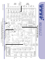
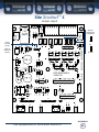
Site Sentinel™ 4 Installation and Operation Manual
Installation
Each buffered metering (analog) input can handle up to (positive only) 10
volts DC and must be ground referenced and connected to the associated MGND
ground terminal. Inputs are self-calibrating and are based on an internal A/D converter with a precision, low-drift voltage reference, so the reading should not drift
over time or with temperature. Metering setup is performed by connecting the sample voltage to the MTRx and MGND metering (analog) input, then calibrated for the
desired value (reading).
Status/Logic Inputs
Each optically isolated status/logic inputs can be configured to accept either
a contact closure (DRY = default) or a (floating, WET) input. Attach your dry contacts to the desired status/logic channels StxA and STxB (where x is the status/logic
input channel) terminals.
Each input is equipped with a four-position header (please refer to the
jumper layout in the appendix). JPR1 supports status/logic input one, JPR2 status/logic input two, JPR3, status/logic input three and JPR4, status/logic input four.
Each jumper (JPRx, where x is the status/logic input) and the header pins 1,2,3,4
(The pin closest to the J of the label JPRx, is pin 1) is used to configure for wet or
dry operation. The factory default is DRY. (Switch, relay contact, open collector)
with jumpers between 1 & 2 and 3 & 4. In the DRY configuration, the “A” terminal is ground while the “B” terminal is the cathode of the opto-isolator diode (pulled
up to 5 volts through a 2.2K resistor).
To change the status/logic input to (floating) WET (user supplied voltage
between 5 and 24 vdc), remove both jumpers and place ONE jumper over pins 2 &
3. Connect the positive voltage to terminal “A” (anode) and ground or minus voltage to terminal “B” (cathode). NOTE: Please observe proper polarity.
Control Relays
Each of the four control relays are supplied with a normally open dry contact. Equipment to be controlled should be connected to the terminals labeled Kx
and Kx (where x is the control relay number) for relays one through four.
Power Failure Input
Connect a user supplied 5 to 12 volts DC only power source (center positive)
to the power failure input labeled PF. The barrel connector size is 2.1mm ID x
5.5mm OD. An inexpensive 5 to 12 volts DC wall transformer of any current of
50ma or more will work. NOTE: The primary (120vac) of the wall transformer
should be connected to the utility company side of your service.
An UPS is suggested to power the Site Sentinel™ 4 during power outages.
NOTE:
Valid sample voltage
MUST be applied to the
metering inputs in order
to perform calibration.
NOTE:
If mechanical latching
relays are required, we
suggest the Broadcast
Tools LR-5 (4PDT &
SPST)
mechanical
latching relay.
INSTALLATION
e-mail: [email protected] voice: 360.854.9559 fax: 866.783.1742
8