1
APPLICATION NOTE
P90CL301 I2C driver routines
AN94078
Philips Semiconductors
P90CL301 I2C driver routines
Application Note
AN94078
Abstract
The P90CL301 is a highly integrated 16/32 bit micro-controller especially suitable for applications requiring low
voltage and low power consumption. It is fully software compatible with the 68000. Furthermore, it provides both
standard as well as advanced peripheral functions on-chip.
One of these peripheral functions is the I2C bus. This report describes worked-out driver software (written in C) to
program the P90CL301 I2C interface. It also contains interface software routines offering the user a quick start in
writing a complete I2C system application.
Purchase of Philips I 2C components conveys a
license under the I 2C patent to use the components in the I2C system, provided the system
conforms to the I 2C specifications defined by
Philips.
© Philips Electronics N.V. 1997
All rights are reserved. Reproduction in whole or in part is prohibited without the prior written consent of the copyright owner.
The information presented in this document does not form part of any quotation or contract, is believed to be
accurate and reliable and may be changed without notice. No liability will be accepted by the publisher for any
consequence of its use. Publication thereof does not convey nor imply any license under patent- or other industrial
or intellectual property rights.
2
Philips Semiconductors
P90CL301 I2C driver routines
Application Note
AN94078
APPLICATION NOTE
P90CL301 I2C driver routines
AN94078
Author(s):
Paul Seerden
Product Concept & Application Laboratory Eindhoven,
The Netherlands
Keywords
Microcontroller (P90CL301)
Driver routines
Application software
I2C bus
(multi)Master-Slave
Date: 1st November, 1994
3
Philips Semiconductors
P90CL301 I2C driver routines
Application Note
AN94078
Summary
This application note shows how to write an Inter Integrated Circuit bus driver (I²C) for the Philips P90CL301
micro-controller.
It is not only an example of writing a driver, but it also includes a set of application interface software routines to
quickly implement a complete I²C multi-master system application.
For specific applications the user will have to make minimal changes in the driver program. Using the driver
means linking modules to your application software and including a header-file into the application source
programs. A small example program of how to use the driver is listed.
The driver supports i.a. polled or interrupt driven message handling, slave message transfers and multi-master
system applications. Furthermore, it is made suitable for use in conjunction with real time operating systems, like
pSOS+.
4
Philips Semiconductors
P90CL301 I2C driver routines
Application Note
AN94078
CONTENTS
1. Introduction . . . . . . . . . . . . . . . . . . . . . . . . . . . . . . . . . . . . . . . . . . . . . . . . . . . . . . . . . . . . . . . . . . . . . . . . . . . . . . . . . . 7
2. Functional description . . . . . . . . . . . . . . . . . . . . . . . . . . . . . . . . . . . . . . . . . . . . . . . . . . . . . . . . . . . . . . . . . . . . . . . . . .
2.1. The I2C bus format . . . . . . . . . . . . . . . . . . . . . . . . . . . . . . . . . . . . . . . . . . . . . . . . . . . . . . . . . . . . . . . . . . . . . . .
2.2. Input definition . . . . . . . . . . . . . . . . . . . . . . . . . . . . . . . . . . . . . . . . . . . . . . . . . . . . . . . . . . . . . . . . . . . . . . . . . . .
2.3. Output definition . . . . . . . . . . . . . . . . . . . . . . . . . . . . . . . . . . . . . . . . . . . . . . . . . . . . . . . . . . . . . . . . . . . . . . . . .
2.4. Performance . . . . . . . . . . . . . . . . . . . . . . . . . . . . . . . . . . . . . . . . . . . . . . . . . . . . . . . . . . . . . . . . . . . . . . . . . . . .
2.5. Using interrupts . . . . . . . . . . . . . . . . . . . . . . . . . . . . . . . . . . . . . . . . . . . . . . . . . . . . . . . . . . . . . . . . . . . . . . . . .
2.6. Using an operating system . . . . . . . . . . . . . . . . . . . . . . . . . . . . . . . . . . . . . . . . . . . . . . . . . . . . . . . . . . . . . . .
2.7. Error handling . . . . . . . . . . . . . . . . . . . . . . . . . . . . . . . . . . . . . . . . . . . . . . . . . . . . . . . . . . . . . . . . . . . . . . . . . .
8
8
9
9
9
10
10
10
3. External (application) interface . . . . . . . . . . . . . . . . . . . . . . . . . . . . . . . . . . . . . . . . . . . . . . . . . . . . . . . . . . . . . . . . .
3.1. External data interface . . . . . . . . . . . . . . . . . . . . . . . . . . . . . . . . . . . . . . . . . . . . . . . . . . . . . . . . . . . . . . . . . . .
3.2. External function interfaces . . . . . . . . . . . . . . . . . . . . . . . . . . . . . . . . . . . . . . . . . . . . . . . . . . . . . . . . . . . . . . .
3.3. Interface layer example . . . . . . . . . . . . . . . . . . . . . . . . . . . . . . . . . . . . . . . . . . . . . . . . . . . . . . . . . . . . . . . . . .
11
11
12
15
4. Internal working . . . . . . . . . . . . . . . . . . . . . . . . . . . . . . . . . . . . . . . . . . . . . . . . . . . . . . . . . . . . . . . . . . . . . . . . . . . . . . 16
5. Slave operation . . . . . . . . . . . . . . . . . . . . . . . . . . . . . . . . . . . . . . . . . . . . . . . . . . . . . . . . . . . . . . . . . . . . . . . . . . . . . . 18
6. Modelling hierarchy . . . . . . . . . . . . . . . . . . . . . . . . . . . . . . . . . . . . . . . . . . . . . . . . . . . . . . . . . . . . . . . . . . . . . . . . . . . 19
Appendices . . . . . . . . . . . . . . . . . . . . . . . . . . . . . . . . . . . . . . . . . . . . . . . . . . . . . . . . . . . . . . . . . . . . . . . . . . . . . . . . . . .
APPENDIX I
I2CINTFC.C . . . . . . . . . . . . . . . . . . . . . . . . . . . . . . . . . . . . . . . . . . . . . . . . . . . . . . . . . . . . . . . . .
APPENDIX II I2CMASTR.C . . . . . . . . . . . . . . . . . . . . . . . . . . . . . . . . . . . . . . . . . . . . . . . . . . . . . . . . . . . . . . .
APPENDIX III I2CSLAVE.C . . . . . . . . . . . . . . . . . . . . . . . . . . . . . . . . . . . . . . . . . . . . . . . . . . . . . . . . . . . . . . . .
APPENDIX IV I2CDRIVR.C . . . . . . . . . . . . . . . . . . . . . . . . . . . . . . . . . . . . . . . . . . . . . . . . . . . . . . . . . . . . . . . .
APPENDIX V I2CEXPRT.H . . . . . . . . . . . . . . . . . . . . . . . . . . . . . . . . . . . . . . . . . . . . . . . . . . . . . . . . . . . . . . . .
APPENDIX VII I2CDRIVR.H . . . . . . . . . . . . . . . . . . . . . . . . . . . . . . . . . . . . . . . . . . . . . . . . . . . . . . . . . . . . . . . .
APPENDIX VII REG90301.H . . . . . . . . . . . . . . . . . . . . . . . . . . . . . . . . . . . . . . . . . . . . . . . . . . . . . . . . . . . . . . . .
APPENDIX VIII EXAMPLE.C . . . . . . . . . . . . . . . . . . . . . . . . . . . . . . . . . . . . . . . . . . . . . . . . . . . . . . . . . . . . . . . .
5
20
20
24
27
30
32
34
35
38
Philips Semiconductors
P90CL301 I2C driver routines
Application Note
AN94078
6
Philips Semiconductors
P90CL301 I2C driver routines
Application Note
AN94078
1. Introduction
This report describes an I²C driver for the P90CL301 16/32 bit 68000 based micro-controller. This driver is the
interface between application software and the I2C device(s). These devices conform to the serial bus interface
protocol specification as described in the I2C reference manual.
The I2C bus consists of two wires carrying information between the devices connected to the bus. Each device
has its own 7-bit address. It can act as a master or as a slave during a data transfer. A master is the device that
initiates the data transfer and generates the clock signals needed for the transfer. At that time any addressed
device is considered a slave. The I2C bus is a multi-master bus. This means that more than one device capable of
controlling the bus can be connected to it.
This driver supports both master and slave message transfers, as well as polled and interrupt-driven message
handling.
The driver will be linked to the application. It is completely written in C programming language. Both the software
structure and the interface to the application are described separately. The driver program has been tested as
thoroughly as time permitted; however, Philips cannot guarantee that this I2C driver is flawless in all applications.
This application note (with C source files) is available for downloading from the PHIBBS (Philips Bulletin
Board System). It is packed in the self extracting PC DOS file: I2C90301.EXE. The system is open to all
callers, operates 24 hours a day and can be accessed with modems up to 9600 baud.
The BBS can be reached via telephone number: +31 40 721102.
Used references:
- The I²C-bus specification
- The I²C-bus and how to use it
- P90CL301 Objective Specification JUN 94
- I2C driver routines for SCC68070 and 9xC10x microcontrollers
- I2C driver routines for the 90CE201 microcontroller
9398 358 10011
9398 393 40011
EIE/AN93001
EIE/AN93002
Used development- and test tools:
- Microtec MCC68k C compiler (version 4.2I)
- Philips Microcore 5 (P90CL301) evaluation board
- Philips I²C-bus evaluation board
- Philips Logic Analyzer PM3580/PM3585 with
I²C-bus support package PF8681
OM5040
OM1016
7
Philips Semiconductors
P90CL301 I2C driver routines
Application Note
AN94078
2. Functional description
2.1. The I2C bus format
An I2C transfer is initiated with the generation of a start condition. The condition will set the bus busy. An I2C
message may be followed either by a stop condition or a repeated start condition. A stop condition will release the
bus mastership. A repeated start offers the possibility to send /receive more than one message to/from the same
or different devices, while retaining bus mastership. Stop and (repeated) start conditions can only be generated
in master mode.
Data and addresses are transferred in eight bit bytes, starting with the most significant bit. During the 9th clock
pulse, following the data byte, the receiver must send an acknowledge bit to the transmitter. The clock speed is
normally 100 KHz. Clock pulses may be stretched (for timing causes) by the slave.
A start condition is always followed by a 7-bits slave address and a R/W direction bit.
In a multi-master system, arbitration is done automatically by the I2C hardware. Arbitration can carry on through
many bits, it can even continue into the comparison of data bytes. If arbitration is lost, this driver switches to slave
mode and automatically back to master mode (retry) after the slave transfer is done.
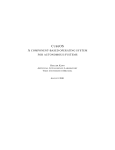
General format and explanation of an I²C message:
S SLV_W A SUB A S SLV_R A D1 A D2 A ........ A Dn N P
S
: (re)Start condition.
A
: Acknowledge on last byte.
N
: No Acknowledge on last byte.
P
: Stop condition.
SLV_W
: Slave address and Write bit.
SLV_R
: Slave address and Read bit.
SUB
: Sub-address.
D1 ... Dn
: Block of data bytes.
also:
D1.1 ... D1.m
: First block of data bytes.
Dn.1 ... Dn.m
: nth block of data bytes.
8
Philips Semiconductors
P90CL301 I2C driver routines
Application Note
AN94078
2.2. Input definition
Inputs (application's view) to the driver are:
The number of messages to exchange (transfer).
The slave address of the I2C device for each message.
The data direction (read/write) for all messages.
The number of bytes in each message.
In case of a write messages: the data bytes to be written.
2.3. Output definition
Outputs (application's view) from the driver are:
Status information (success or error code).
The number of messages actually transferred (not equal to the requested number of messages in case of
an error).
For each read message: The data bytes read.
2.4. Performance
The clock speed of the I²C-bus depends of the oscillator frequency of your controller. To set the right speed in the
P90CL301 two registers have to be written: SYSCON and SCON. Therefore, no constant definitions are given in
the file I2CDRIVR.H. The clock speed is programmable ranging up to 100 KHz. To select the correct initialization
divisor values, refer to the User's Manual or the data sheet of the P90CL301.
After that change the SCON values in the file I2CDRIVR.H (with the correct CR2, CR1 and CR0 bits; default 000)
and re-compile the module I2CDRIVR.C.
9
Philips Semiconductors
P90CL301 I2C driver routines
Application Note
AN94078
2.5. Using interrupts
Normally (default) the driver operates in polling mode. If a transfer is applied for, the driver interface function will
not return until the transfer has ended.
To let the driver operate in interrupt driven mode, the I2C_InstallInterrupt function must be called after
initialization. Furthermore, the user has to put a vector in the interrupt vector table (can be in RAM or ROM). This
vector is a pointer to the interrupt routine called I2C_Interrupt. The user also has to determine the priority level of
the interrupt.
If a transfer is started now, the driver interface function returns immediately.
At the end of the transfer (polled or interrupt driven), together with the generate stop condition, the driver calls a
function that was given by the application, at the time the transfer was applied for. It's up to the user to write this
function and to determine the actions that have to be done. (see example I2CINTFC.C).
2.6. Using an operating system
If you want to use this driver together with a multi-tasking (real time) operating system (like pSOS+), you only have
to write or adjust the interface file I2CINTFC.C (I2CDRIVR.C remains unchanged).
At the place in the interface software where the driver program is called, operating system calls have to be used.
Examples of these calls are 'wait for/set semaphore' or 'send/receive mail', program time-outs, etc. This way other
tasks in your system will not be blocked.
2.7. Error handling
Normally, before sending or receiving a message using an I/O driver, a 'time-out' is programmed. Main reason for
these time-outs is to locate hardware failures, like 'break in the cable', 'remote system not responding' or 'interface
hardware failure'. However, to program a time-out a hardware timer (or an operating system) is needed.
Therefore, the driver package does not support these time-outs (too much application and system-environment
dependent).
Also message retries are not supported by the driver, because they often happen simultaneously with time-outs.
Nevertheless, the example given in this report shows you how to simply add retries and time-outs (software loops)
to your driver interface (see I2CINTFC.C).
Furthermore, a status error is passed every time the transfer ready function is called by the driver. It's up to the
user to handle possible errors.
10
Philips Semiconductors
P90CL301 I2C driver routines
Application Note
AN94078
3. External (application) interface
This section specifies the external interface of the driver towards the application. The C-coded external interface
definitions are in the include file I2CEXPRT.H.
The application's view on the I2C bus is quite simple: The application can send messages to an I2C device.
Moreover, the application must be able to exchange a group of messages, optionally addressed to different
devices, without losing bus mastership. Retaining the bus is needed to guarantee atomic operations.
3.1. External data interface
All parameters affected by an I²C master transfer are logically grouped within two data structures. The user fills
these structures and then calls the interface function to perform a transfer. The data structures used are listed
below.
typedef struct
{
BYTE
I2C_MESSAGE
nrMessages;
**p_message;
/* total number of messages
/* ptr to array of ptrs to message parameter blocks
*/
*/
} I2C_TRANSFER;
The structure I2C_TRANSFER contains the common parameters for an I2C transfer. The driver keeps a local copy
of these parameters and leaves the contents of the structure unchanged. So, in many applications the structure
only needs to be filled once.
After finishing the actual transfer, a 'transfer ready' function is called. The driver status and the number of
messages done, are passed to this function.
The structure contains a pointer (p_message) to an array with pointers to the structure I2C_MESSAGE, shown
below.
typedef struct
{
BYTE
BYTE
BYTE
address;
nrBytes;
*buf;
/* The I2C slave device address
/* number of bytes to read or write
/* pointer to data array
} I2C_MESSAGE;
11
*/
*/
*/
Philips Semiconductors
P90CL301 I2C driver routines
Application Note
AN94078
The direction of the transfer (read or write) is determined by the lowest bit of the slave address;
write = 0 and read = 1. This bit must be re-set by the application.
The array buf must contain data supplied by the application in case of a write transfer. The user should notice that
checking to ensure that the buffer pointed to by buf is at least nrBytes in length, cannot be done by the driver.
Otherwise, the array is filled by the driver. If you want to use buf as a string, a terminating NULL should be added
at the end. It is the users responsibility to ensure that the buffer pointed to by buf is large enough to receive
nrBytes bytes.
3.2. External function interfaces
This section gives a description of each callable interface function in the I²C driver module.
First the initialization functions are discussed. These functions directly program the I²C interface hardware and are
part of the low level driver software. They must be called only once after 'reset', but before any transfer function is
executed. The driver contains the following three functions:
- I2C_InitializeMaster
(in file I2CMASTR.C)
- I2C_InitializeSlave
(in file I2CSLAVE.C)
- I2C_InstallInterrupt
(in file I2CDRIVR.C)
Next two functions to 'perform transfers' will be discussed.
- I2C_Transfer
(in file I2CMASTR.C)
- I2C_ProcessSlave
(in file I2CSLAVE.C)
12
Philips Semiconductors
P90CL301 I2C driver routines
Application Note
AN94078
void I2C_InitializeMaster(void)
Initialize the I²C-bus master driver part. Hardware I²C registers of the P90CL301 interface will be
programmed. Used constants(parameters) are defined in the file I2CDRIVR.H. Must be called once after
RESET, before any other interface function is called.
void I2C_InitializeSlave(BYTE ownAddress, BYTE *buf, BYTE size)
Initialize the I²C-bus slave driver part. Hardware I²C registers of the P90CL301 interface will be
programmed with the designated parameters. Must be called once after RESET.
BYTE ownAdress
Micro-controller's own slave-address.
BYTE *buf
Pointer to buffer, to transmit data from, or receive data in.
BYTE size
Size of buffer to transmit data from, or receive data in.
void I2C_InstallInterrupt(BYTE intLevel)
Install the I²C interrupt, using the specified priority. Must be called once after one of the initialization
functions is called.
BYTE intLevel
Interrupt level (priority) of the I²C interface.
In addition to the installation of the I²C interrupt the user has to install the interrupt vector. This vector is a
pointer to the interrupt routine and must be placed in the interrupt vector table. This table can be located in
RAM or ROM. The interrupt function prototype is given in the file I2CEXPRT.H.
See file EXAMPLE.C, for an example of initializing a vector in a RAM table.
13
Philips Semiconductors
P90CL301 I2C driver routines
Application Note
AN94078
void I2C_Transfer(I2C_TRANSFER *p, void (*proc)(BYTE status, BYTE msgsDone))
Start a synchronous I2C transfer. When the transfer is completed, with or without an error, call the function
proc, passing the transfer status and the number of messages successfully transferred.
I2C_TRANSFER *p
A pointer to the structure describing the I²C messages to be transferred.
void (*proc(status, msgsDone)) A pointer to the function to be called when the transfer is completed.
BYTE msgsDone
Number of message successfully transferred.
BYTE status
one of:
I2C_OK
Transfer ended No Errors
I2C_BUSY
I²C busy, so wait
I2C_ERR
General error
I2C_NO_DATA
err: No data message block
I2C_NACK_ON_DATA
err: No ack on data in block
I2C_NACK_ON_ADDRESS
err: No ack of slave
I2C_DEVICE_NOT_PRESENT err: Device not present
I2C_ARBITRATION_LOST
err: Arbitration lost
I2C_TIME_OUT
err: Time out occurred
I2C_SLAVE_ERROR
Slave mode error
I2C_INIT_ERROR
err: Initialization (not done)
void I2C_ProcessSlave(void)
This function can be used by the application to handle slave transfers. It is just an example and should be
customized by the user. Depending of the status of the slave it takes action. Possible slave states are:
SLAVE_IDLE
Slave is idle
SLAVE_BUSY
Transfer busy
SLAVE_READY
Slave transfer done.
SLAVE_TRX_ERROR
Transmit data error
SLAVE_RCV_ERROR
Receive data error
14
Philips Semiconductors
P90CL301 I2C driver routines
Application Note
AN94078
3.3. Interface layer example
The module I2CINTFC.C gives an example of how to implement a few basic transfer functions (see also previous
PCALE I2C driver application notes). These functions allow you to communicate with most of the available I²C
devices and serve as a layer between your application and the driver software. This layered approach allows
support for new devices (micro-controllers) without re-writing the high-level (device-independent) code. The given
examples are:
void I2C_Write(I2C_MESSAGE *msg)
void I2C_WriteRepWrite(I2C_MESSAGE *msg1, I2C_MESSAGE *msg2)
void I2C_WriteRepRead(I2C_MESSAGE *msg1, I2C_MESSAGE *msg2)
void I2C_Read(I2C_MESSAGE *msg)
void I2C_ReadRepRead(I2C_MESSAGE *msg1, I2C_MESSAGE *msg2)
void I2C_ReadRepWrite(I2C_MESSAGE *msg1, I2C_MESSAGE *msg2)
Furthermore, the module I2CINTFC.C contains the functions StartTransfer, in which the actual call to the driver
program is done, and the function I2cReady, which is called by the driver after the completion of a transfer. The
flag drvStatus is used to test/check the state of a transfer.
In the StartTransfer function a software time-out loop is programmed. Inside this time-out loop the
MainStateHandler is called if the driver is in polling mode and the SCON SI flag is set.
If a transfer has failed (error or time-out) the StartTransfer function prints an error message (via UART to
Microcore 5 HMON terminal) and it does a retry of the transfer. However, if the maximum number of retries is
reached an exception interrupt (Trap #15) is generated, through which the micro jumps into the HMON debug
monitor code on the Microcore 5.
15
Philips Semiconductors
P90CL301 I2C driver routines
Application Note
AN94078
4. Internal working
The P90CL301 on-chip logic provides a serial interface that meets the I2C bus specification and supports all
transfer modes from and to the bus. In order to enable the interface the port pins P10 and P11 should be
programmed to their alternate function, by writing to the port control register PCON.
The CPU interfaces to the I2C logic via four hardware registers: SCON (control register), SSTA (status register),
SDAT (data register) and SADR (slave address registers).
After completing the transmission or reception of each byte (address or data), the SI flag in the SCON register is
set. In interrupt driven mode, an interrupt is sent to the micro and the interrupt service handler will be called. In
polling mode this is done by software. At that time register SSTA holds one of the following status codes:
Master transmitter:
08H
- A start condition has been transmitted
10H
- A repeated start condition has been transmitted
18H
- SLV_W has been transmitted, ACK received
20H
- SLV_W has been transmitted, NOTACK received
28H
- DATA from SDAT has been transmitted, ACK received
30H
- DATA from SDAT has been transmitted, NOTACK received
38H
- Arbitration lost in SLV_ R/W or DATA
Master receiver:
38H
- Arbitration lost while returning NOTACK
40H
- SLV_R has been transmitted, ACK received
48H
- SLV_R has been transmitted, NOTACK received
50H
- DATA in SDAT received, ACK returned
58H
- DATA in SDAT received, NOTACK returned
Slave receiver:
60H
- Own SLV_W has been received, ACK returned
68H
- Arbitration lost in SLV_R/W as master, own SLV_W received, ACK returned
70H
- General call has been received, ACK returned
78H
- Arbitration lost in SLV_R/W as master, general call received, ACK returned
80H
- Addressed with own slave,Data byte received in SDAT, ACK returned
88H
- Addressed with own slave, Data byte received in SDAT, NOTACK returned
90H
- Addressed with general call, Data byte received in SDAT, ACK returned
98H
- Addressed with general call, Data byte received in SDAT, NOTACK returned
A0H
- A STOP or repeated START condition has been received
16
Philips Semiconductors
P90CL301 I2C driver routines
Application Note
AN94078
Slave transmitter:
A0H
- A STOP or repeated START condition has been received
A8H
- Own SLV_R has been received, ACK returned
B0H
- Arbitration lost in SLV_R/W as master, own SLV_R received, ACK returned
B8H
- Data byte has been transmitted, ACK received
C0H
- Data byte has been transmitted, NOTACK received
Miscellaneous:
00H
- Bus error during master or selected slave mode, due to an erroneous START or STOP
condition.
The procedure MainStateHandler (in I2CDRIVR.C) checks the status in SSTA and calls either the function
HandleMasterState (in I2CMASTR.C) or the function HandleSlaveState (in I2CSLAVE.C). Calling of these
functions is done via two (initialized) pointers.
Both functions contain a switch (case) statement on SSTA to handle the right I2C status.
If a master transfer is completed a function (readyProc) in the application (or interface) is called.
If a slave transfer is completed the slave status SLAVE_READY is set (see also section 3.2).
17
Philips Semiconductors
P90CL301 I2C driver routines
Application Note
AN94078
5. Slave operation
The slave-mode protocol is very specific to the system design, and therefore, very difficult to make generic.
In this report basic slave-receive and slave-transmit routines are given, but they only should be considered as
examples. To activate the slave mode driver, call the function I2C_InitializeSlave (see also section 3.2). All slave
routines are placed together in the module I2CSLAVE.C, this module is listed in appendix III.
There are two ways for the driver to enter the slave functions:
-
Through a normal I²C interrupt (or polling the slave) when the driver is idle (in slave receiver mode) and
the interface recognizes its own slave address, or a general call address.
-
Through master mode, during transmission of a slave-address in master mode arbitration is lost to
another master. The driver must then switch to slave-receiver mode to check if this other master wants to
address him.
The slave routines as given, make use of a single data buffer. This buffer (pointer and size) is initialized during the
I2C_InitializeSlave function.
When addressed as slave transmitter, bytes from the data buffer are transmitted until a NACK (No Acknowledge)
or a stop condition is received.
When addressed as slave receiver, bytes from the I²C-bus are received into the data buffer until it is full (size is
reached). The transmission is stopped by the driver by giving no acknowledge on the last data byte.
After a slave transfer the application must service the slave (i.e. process received data or put new data in the
buffer). This is very application dependent, therefore the example function I2C_ProcessSlave must be customized
by the user.
18
Philips Semiconductors
P90CL301 I2C driver routines
Application Note
AN94078
6. Modelling hierarchy
This I2C driver consists of 3 parts:
- Driver software; Initialization, Master functions, Slave functions.
- Interface functions; External application interface to the driver.
- An application example running on the Microcore 5 (is a P90CL301 evaluation tool).
The driver package contains the following files:
- I2CDRIVR.C
The general driver needed for both master and slave features, containing the interrupt
installation and handler. Always link this module to your application.
- I2CMASTR.C
The actual driver for master transfers, containing initialization and master state handling.
Only needed if your P90CL301 acts as a bus master.
- I2CSLAVE.C
The actual driver functions needed for the micro to act as a slave on the bus, containing
initialization and state handling.
- I2CDRIVR.H
This module (include file) contains definitions of local data types and constants, and is used
only by the driver package.
- I2CINTFC.C
This module contains example application interface functions to perform a master transfer. In
this module some often used message protocols are implemented. Furthermore, it shows
examples of error handling, like: time-outs (software loops), retries and error messages. The
user must adapt these functions to his own system needs.
- I2CEXPRT.H
This module (include file) contains definitions of all 'global' constants, function prototypes,
data types and structures needed by the user (application). Include this file in the user
application source files.
- EXAMPLE.C
This program uses the driver package to implement a simple application on the Microcore 5
and an I2C demonstration board.
There are different approaches to link your driver and application software. One of them is that you separately link
the object (.obj) files your application needs. A second possibility is to use the driver package library, called
I2C90301.LIB, which is also at the distribution disk. This approach has the advantage that depending on the
function calls in your code, the linker loads object modules from the library.
19
Philips Semiconductors
P90CL301 I2C driver routines
Application Note
AN94078
Appendices
APPENDIX I
I2CINTFC.C
/***************************************************************************/
/* Acronym
: I²C Inter IC bus (for P90CL301)
*/
/* Name of module
: I2CINTFC.C
*/
/* Scope
: general I²C driver
*/
/* 12nc
: xxxx xxx xxxx.x
*/
/* Creation date
: 1994-08-19
*/
/* Program language : C
*/
/* Name
: P.H. Seerden
*/
/*
*/
/*
*/
/*
(C) Copyright 1994 Philips Semiconductors B.V.
*/
/*
Product Concept & Application Laboratory Eindhoven (PCALE)
*/
/*
Eindhoven - The Netherlands
*/
/*
*/
/* All rights are reserved. Reproduction in whole or in part is
*/
/* prohibited without the written consent of the copyright owner.
*/
/*
*/
/***************************************************************************/
/*
*/
/* Description:
*/
/*
*/
/*
External interface to the driver for the I²C interface on the
*/
/*
Philips P90CL301 microcontroller.
*/
/*
*/
/*
This module contains the EXAMPLE interface functions, used by
*/
/*
the application to do I²C master-mode transfers.
*/
/*
*/
/***************************************************************************/
/*
*/
/* History:
*/
/*
*/
/* 94-02-22
P.H. Seerden
Initial version
*/
/*
*/
/*
*/
/***************************************************************************/
#include "i2cexprt.h"
#include "i2cdrivr.h"
#include "reg90301.h"
static BYTE drvStatus;
static I2C_MESSAGE
static I2C_TRANSFER
*p_iicMsg[2];
iicTfr;
/* Status returned by driver
*/
/* pointer to an array of (2) I2C mess */
static void I2cReady(BYTE status, BYTE msgsDone)
/***********************************************
* Input(s)
: status
Status of the driver at completion time
*
msgsDone
Number of messages completed by the driver
* Output(s) : None.
* Returns
: None.
* Description: Signal the completion of an I²C transfer. This function is
*
passed (as parameter) to the driver and called by the
*
drivers interrupt handler (!).
***************************************************************************/
{
drvStatus = status;
}
20
Philips Semiconductors
P90CL301 I2C driver routines
Application Note
AN94078
static void StartTransfer(void)
/******************************
* Input(s)
: None.
* Output(s) : statusfield of I2C_TRANSFER contains the driver status:
*
I2C_OK
Transfer was successful.
*
I2C_TIME_OUT
Timeout occurred
*
Otherwise
Some error occurred.
* Returns
: None.
* Description: Start I²C transfer and wait (with timeout) until the
*
driver has completed the transfer(s).
***************************************************************************/
{
LONG timeOut;
BYTE retries = 0;
do
{
drvStatus = I2C_BUSY;
I2C_Transfer(&iicTfr, I2cReady);
timeOut = 0;
while (drvStatus == I2C_BUSY)
{
if (++timeOut > 60000)
drvStatus = I2C_TIME_OUT;
if ((PICR3 & 0x70) == 0)
{
if (SCON & 0x08)
MainStateHandler();
}
}
/* level 0 -> polling
*/
/* wait until SI bit is set
*/
if (retries == 6)
{
printf("retry counter expired\n");
/* fatal error ! So, ..
asm (" trap #15 ");
/* escape to debug monitor
}
else
retries++;
switch (drvStatus)
{
case I2C_OK
case I2C_NO_DATA
case I2C_NACK_ON_DATA
case I2C_NACK_ON_ADDRESS
case I2C_DEVICE_NOT_PRESENT
case I2C_ARBITRATION_LOST
case I2C_TIME_OUT
default
}
} while (drvStatus != I2C_OK);
: break;
: printf("buffer empty\n");
: printf("no ack on data\n");
: printf("no ack on address\n");
: printf("device not present\n");
: printf("arbitration lost\n");
: printf("time-out\n");
: printf("unknown status\n");
}
21
*/
*/
break;
break;
break;
break;
break;
break;
break;
Philips Semiconductors
P90CL301 I2C driver routines
Application Note
AN94078
void I2C_Write(I2C_MESSAGE *msg)
/*******************************
* Input(s)
: msg
I²C message
* Returns
: None.
* Description: Write a message to a slave device.
* PROTOCOL
: <S><SlvA><W><A><D1><A> ... <Dnum><N><P>
***************************************************************************/
{
iicTfr.nrMessages = 1;
iicTfr.p_message = p_iicMsg;
p_iicMsg[0] = msg;
StartTransfer();
}
void I2C_WriteRepWrite(I2C_MESSAGE *msg1, I2C_MESSAGE *msg2)
/***********************************************************
* Input(s)
: msg1
first I²C message
*
msg2
second I²C message
* Returns
: None.
* Description: Writes two messages to different slave devices separated
*
by a repeated start condition.
* PROTOCOL
: <S><Slv1A><W><A><D1><A>...<Dnum1><A>
*
<S><Slv2A><W><A><D1><A>...<Dnum2><A><P>
***************************************************************************/
{
iicTfr.nrMessages = 2;
iicTfr.p_message = p_iicMsg;
p_iicMsg[0] = msg1;
p_iicMsg[1] = msg2;
StartTransfer();
}
void I2C_WriteRepRead(I2C_MESSAGE *msg1, I2C_MESSAGE *msg2)
/**********************************************************
* Input(s)
: msg1
first I²C message
*
msg2
second I²C message
* Returns
: None.
* Description: A message is sent and received to/from two different
*
slave devices, separated by a repeat start condition.
* PROTOCOL
: <S><Slv1A><W><A><D1><A>...<Dnum1><A>
*
<S><Slv2A><R><A><D1><A>...<Dnum2><N><P>
***************************************************************************/
{
iicTfr.nrMessages = 2;
iicTfr.p_message = p_iicMsg;
p_iicMsg[0] = msg1;
p_iicMsg[1] = msg2;
StartTransfer();
}
void I2C_Read(I2C_MESSAGE *msg)
/******************************
* Input(s)
: msg
I²C message
* Returns
: None.
* Description: Read a message from a slave device.
* PROTOCOL
: <S><SlvA><R><A><D1><A> ... <Dnum><N><P>
***************************************************************************/
{
iicTfr.nrMessages = 1;
iicTfr.p_message = p_iicMsg;
p_iicMsg[0] = msg;
StartTransfer();
}
22
Philips Semiconductors
P90CL301 I2C driver routines
Application Note
AN94078
void I2C_ReadRepRead(I2C_MESSAGE *msg1, I2C_MESSAGE *msg2)
/*********************************************************
* Input(s)
: msg1
first I²C message
*
msg2
second I²C message
* Returns
: None.
* Description: Two messages are read from two different slave devices,
*
separated by a repeated start condition.
* PROTOCOL
: <S><Slv1A><R><A><D1><A>...<Dnum1><N>
*
<S><Slv2A><R><A><D1><A>...<Dnum2><N><P>
***************************************************************************/
{
iicTfr.nrMessages = 2;
iicTfr.p_message = p_iicMsg;
p_iicMsg[0] = msg1;
p_iicMsg[1] = msg2;
StartTransfer();
}
void I2C_ReadRepWrite(I2C_MESSAGE *msg1, I2C_MESSAGE *msg2)
/**********************************************************
* Input(s)
: msg1
first I²C message
*
msg2
second I²C message
* Returns
: None.
* Description: A block data is received from a slave device, and also
*
a(nother) block data is send to another slave device
*
both blocks are separated by a repeated start.
* PROTOCOL
: <S><Slv1A><R><A><D1><A>...<Dnum1><N>
*
<S><Slv2A><W><A><D1><A>...<Dnum2><A><P>
***************************************************************************/
{
iicTfr.nrMessages = 2;
iicTfr.p_message = p_iicMsg;
p_iicMsg[0] = msg1;
p_iicMsg[1] = msg2;
StartTransfer();
}
23
Philips Semiconductors
P90CL301 I2C driver routines
APPENDIX II
Application Note
AN94078
I2CMASTR.C
/***************************************************************************/
/* Acronym
: I²C Inter IC bus (for P90CL301)
*/
/* Name of module
: I2CMASTR.C
*/
/* Scope
: Universal I²C driver
*/
/* 12nc
: xxxx xxx xxxx.x
*/
/* Creation date
: 1994-08-08
*/
/* Program language : C
*/
/* Name
: P.H. Seerden
*/
/*
*/
/*
*/
/*
(C) Copyright 1994 Philips Semiconductors B.V.
*/
/*
Product Concept & Application Laboratory Eindhoven (PCALE)
*/
/*
Eindhoven - The Netherlands
*/
/*
*/
/* All rights are reserved. Reproduction in whole or in part is
*/
/* prohibited without the written consent of the copyright owner.
*/
/*
*/
/***************************************************************************/
/*
*/
/* Description:
*/
/*
*/
/*
Driver for the I²C hardware interface on the Philips P90CL301
*/
/*
microcontroller.
*/
/*
*/
/*
Part of the driver that handles master bus-transfers.
*/
/*
Everything between a Start and Stop condition is called a TRANSFER.
*/
/*
One transfer consists of one or more MESSAGEs.
*/
/*
To start a transfer call function "I2C_Transfer".
*/
/*
*/
/***************************************************************************/
/*
*/
/* History:
*/
/*
*/
/* 94-08-08
P.H. Seerden
Initial version
*/
/*
*/
/*
*/
/***************************************************************************/
#include "i2cexprt.h"
#include "i2cdrivr.h"
#include "reg90301.h"
extern void (*masterProc)();
static I2C_TRANSFER *tfr;
static I2C_MESSAGE *msg;
/* Ptr to active transfer block
/* ptr to active message block
static void (*readyProc)(BYTE,BYTE); /* proc. to call if transfer ended
static BYTE msgCount;
/* Number of messages to sent
static BYTE dataCount;
/* bytes send/received of current message
24
*/
*/
*/
*/
*/
Philips Semiconductors
P90CL301 I2C driver routines
Application Note
AN94078
static void HandleMasterState(void)
/**********************************
* Input(s)
: none.
* Output(s)
: none.
* Returns
: none.
* Description : Master mode state handler for I2C bus.
***************************************************************************/
{
switch(SSTA >> 3)
/* >> 3 for faster code
*/
{
/* 00 */case 0 :
/* Bus Error has occurred
*/
SCON = GENERATE_STOP;
/* release bus, clr STA and SI
*/
break;
/* 08 */case 1 :
/* (repeated) Start condition has been transmitted */
/* 10 */case 2 :
/* Slave address + R/W are transmitted
*/
SDAT = msg->address;
SCON = RELEASE_BUS_ACK;
/* clr STO, STA, SI and set AA
*/
break;
/* 18 */case 3 :
/* SLA+W or DATA transmitted, ACK received
*/
/* 28 */case 5 :
/* DATA or STOP will be transmitted
*/
if (dataCount < msg->nrBytes)
{
SDAT = msg->buf[dataCount++];
/* sent first byte
*/
SCON = RELEASE_BUS_ACK;
/* clr STA, SI
*/
} else
{
if (msgCount < tfr->nrMessages)
{
dataCount = 0;
msg = tfr->p_message[msgCount++];
/* next message */
SCON = RELEASE_BUS_STA;
/* generate (rep)START
*/
} else
{
SCON = GENERATE_STOP;
readyProc(I2C_OK, msgCount);
}
}
break;
/* 20 */case 4 :
/* 48 */case 9 :
/* SLA+W/R transmitted, NOT ACK received
*/
readyProc(I2C_NACK_ON_ADDRESS, msgCount); /* driver finished */
SCON = GENERATE_STOP;
break;
/* 30 */case 6 :
/* DATA transmitted, NOT ACK received
*/
readyProc(I2C_NACK_ON_DATA, msgCount);
SCON = GENERATE_STOP;
break;
/* 38 */case 7 :
/* Arbitration lost in SLA+W or DATA
*/
SCON = RELEASE_BUS_STA;
/* release bus, set STA
*/
break;
/* 40 */case 8 :
/* SLA+R transmitted, ACK received
*/
if (msg->nrBytes == 1)
SCON = RELEASE_BUS_NOACK;
/* No ack on next byte
*/
else
SCON = RELEASE_BUS_ACK;
/* ACK on next byte
*/
break;
/* 50 */case 10 :
/* DATA received, ACK has been returned
*/
msg->buf[dataCount++] = SDAT;
/* read next data
*/
if (dataCount + 1 == msg->nrBytes) /* next byte the last ?
SCON = RELEASE_BUS_NOACK;
/* No ack on next byte
else
SCON = RELEASE_BUS_ACK;
/* return ACK
break;
/* 58 */case 11 :
/* DATA received, NOT ACK has been returned
msg->buf[dataCount] = SDAT;
/* read last data
if (msgCount < tfr->nrMessages)
{
dataCount = 0;
msg = tfr->p_message[msgCount++];
/* next message
SCON = RELEASE_BUS_STA;
/* generate (rep)START
} else
{
SCON = GENERATE_STOP;
readyProc(I2C_OK, msgCount);
}
}
}
25
*/
*/
*/
*/
*/
*/
*/
Philips Semiconductors
P90CL301 I2C driver routines
Application Note
AN94078
void I2C_InitializeMaster(void)
/******************************
* Input(s)
: None.
* Output(s)
: None.
* Returns
: None.
* Description : Enable I²C bus and set the clock speed for I²C.
***************************************************************************/
{
masterProc = HandleMasterState;
PCON |= 0x0C;
SADR = 0x26;
SCON = RELEASE_BUS_ACK;
/* set alternate I/O port function to I²C
/* set default slave address
/* set speed and enable I²C hardware
*/
*/
*/
}
void I2C_Transfer(I2C_TRANSFER *p, void (*proc)(BYTE, BYTE))
/***********************************************************
* Input(s)
: p
address of I²C transfer parameter block.
*
proc
procedure to call when transfer completed,
*
with the driver status and the nr of mesgs
*
passed as parameters.
* Output(s) : None.
* Returns
: None.
* Description: Start an I²C transfer, containing 1 or more messages. The
*
application must leave the transfer parameter block
*
untouched until the ready procedure is called.
*
The first I²C message is started with sending a start
*
condition followed by the slave address.
***************************************************************************/
{
tfr = p;
readyProc = proc;
msgCount = 0;
dataCount = 0;
msg = tfr->p_message[msgCount++];
/* first message to send
*/
SCON = RELEASE_BUS_STA;
/* generate START condition
}
26
*/
Philips Semiconductors
P90CL301 I2C driver routines
Application Note
AN94078
APPENDIX III I2CSLAVE.C
/***************************************************************************/
/* Acronym
: I²C Inter IC bus (for P90CL301)
*/
/* Name of module
: I2CSLAVE.C
*/
/* Scope
: Universal I²C driver
*/
/* 12nc
: xxxx xxx xxxx.x
*/
/* Creation date
: 1994-08-08
*/
/* Program language : C
*/
/* Name
: P.H. Seerden
*/
/*
*/
/*
*/
/*
(C) Copyright 1994 Philips Semiconductors B.V.
*/
/*
Product Concept & Application Laboratory Eindhoven (PCALE)
*/
/*
Eindhoven - The Netherlands
*/
/*
*/
/* All rights are reserved. Reproduction in whole or in part is
*/
/* prohibited without the written consent of the copyright owner.
*/
/*
*/
/***************************************************************************/
/*
*/
/* Description:
*/
/*
*/
/*
Driver for the I²C hardware interface on the Philips P90CL301
*/
/*
microcontroller.
*/
/*
*/
/*
Part of the driver that handles slave bus-transfers.
*/
/*
*/
/***************************************************************************/
/*
*/
/* History:
*/
/*
*/
/* 94-08-08
P.H. Seerden
Initial version
*/
/*
*/
/*
*/
/***************************************************************************/
#include "i2cexprt.h"
#include "i2cdrivr.h"
#include "reg90301.h"
extern void (*slaveProc)();
static
static
static
static
BYTE
BYTE
BYTE
BYTE
count;
*slaveBuf;
size;
slaveStatus;
/*
/*
/*
/*
bytes send/received of current message
ptr to rec/trm data into/from if slave
size of slave mode buffer
status of the slave
27
*/
*/
*/
*/
Philips Semiconductors
P90CL301 I2C driver routines
Application Note
AN94078
void HandleSlaveState(void)
/**************************
* Input(s)
: none.
* Output(s)
: none.
* Returns
: none.
* Description : State handler for I2C.
***************************************************************************/
{
switch(SSTA >> 3)
/* >> 3 for faster code
*/
{
/* 60 */case 12 :
/* 68 */case 13 :
/* Addressed as slave
*/
/* 70 */case 14 :
/* 78 */case 15 :
slaveStatus = SLAVE_BUSY;
count = 0;
if (size > 1)
SCON = RELEASE_BUS_ACK;
/* return ACK on first byte
*/
else
SCON = RELEASE_BUS_NOACK;
/* return NACK on first byte
*/
break;
/* 80 */case 16 :
/* 90 */case 18 :
/* Data received, ACK returned */
slaveBuf[count++] = SDAT;
/* read data
*/
if (count == size)
SCON = RELEASE_BUS_NOACK;
/* return NACK on next byte
*/
else
SCON = RELEASE_BUS_ACK;
/* return ACK on next byte
*/
break;
/* 88 */case 17 :
/* 98 */case 19 :
/* data byte received, NACK returned
*/
slaveStatus = SLAVE_RCV_ERROR;
SCON = RELEASE_BUS_ACK;
/* clr SI, set AA
*/
break;
/* A0 */case 20 : /* STOP or REP.START received, while addressed as slave */
slaveStatus = SLAVE_READY;
SCON = RELEASE_BUS_ACK;
/* clr SI, set AA
*/
break;
/* B0 */case 22 :
/* Arb. lost as MST, addressed as slave transmitter */
slaveStatus = SLAVE_BUSY;
count = 0;
SDAT = slaveBuf[count++];
/* Transmit next data, restart
*/
SCON = RELEASE_BUS_STA;
/* MST mode if bus is free again */
break;
/* A8 */case 21 :
/* Addressed as slave transmitter
*/
slaveStatus = SLAVE_BUSY;
count = 0;
/* B8 */case 23 :
/* Data transmitted, ACK received
*/
SDAT = slaveBuf[count++];
/* Transmit next data
*/
SCON = RELEASE_BUS_ACK;
/* clr SI, set AA
*/
break;
/* C0 */case 24 :
/* Data transmitted, NOT ACK received
*/
slaveStatus = SLAVE_TRX_ERROR;
/* C8 */case 25 :
SCON = RELEASE_BUS_ACK;
/* clr SI, set AA
*/
break;
}
}
28
Philips Semiconductors
P90CL301 I2C driver routines
Application Note
AN94078
void I2C_InitializeSlave(BYTE slv, BYTE *buf, BYTE size)
/*******************************************************
* Input(s)
: slv
Own slave address
*
buf
Pointer to slave data buffer
*
size
size of the slave data buffer
* Output(s)
: None.
* Returns
: None.
* Description : Enable I²C (slave) bus and set the clock speed for I²C.
***************************************************************************/
{
slaveProc = HandleSlaveState;
slaveStatus = SLAVE_IDLE;
slaveBuf = buf;
size = size;
PCON |= 0x0C;
SADR = slv;
SCON = RELEASE_BUS_ACK;
/* set alternate I/O port function to I²C
/* own slave address
/* set speed and enable I²C hardware
*/
*/
*/
}
void I2C_ProcessSlave(void)
/**************************
* Input(s)
: None.
* Output(s) : None.
* Returns
: None.
* Description: Process the slave.
*
This function must be called by the application to check
*
the slave status. The USER should adapt this function to
*
his personal needs (take the right action at a certain
*
status).
***************************************************************************/
{
switch(slaveStatus)
{
case SLAVE_IDLE :
/* do nothing or fill transmit buffer for transfer
*/
break;
case SLAVE_BUSY :
/* do nothing if interrupt driven, else poll SCON.SI bit
*/
if ((PICR3 & 0x70) == 0)
/* level 0 -> polling
*/
{
if (SCON & 0x08)
/* wait until SI bit is set
*/
MainStateHandler();
}
break;
case SLAVE_READY :
/* read or fill buffer for next transfer, signal application
*/
slaveStatus = SLAVE_IDLE;
break;
case SLAVE_TRX_ERROR :
/* generate error message
*/
slaveStatus = SLAVE_IDLE;
break;
case SLAVE_RCV_ERROR :
/* generate error message
*/
slaveStatus = SLAVE_IDLE;
break;
}
}
29
Philips Semiconductors
P90CL301 I2C driver routines
APPENDIX IV
Application Note
AN94078
I2CDRIVR.C
/***************************************************************************/
/* Acronym
: I²C Inter IC bus (for P90CL301)
*/
/* Name of module
: I2CDRIVR.C
*/
/* Scope
: Universal I²C driver
*/
/* 12nc
: xxxx xxx xxxx.x
*/
/* Creation date
: 1994-08-08
*/
/* Program language : C
*/
/* Name
: P.H. Seerden
*/
/*
*/
/*
*/
/*
(C) Copyright 1994 Philips Semiconductors B.V.
*/
/*
Product Concept & Application Laboratory Eindhoven (PCALE)
*/
/*
Eindhoven - The Netherlands
*/
/*
*/
/* All rights are reserved. Reproduction in whole or in part is
*/
/* prohibited without the written consent of the copyright owner.
*/
/*
*/
/***************************************************************************/
/*
*/
/* Description:
*/
/*
*/
/*
Driver for the I²C hardware interface on the Philips P90CL301
*/
/*
microcontroller.
*/
/*
*/
/*
Main part of the driver.
*/
/*
Contains the interrupt handler and does calls to the master
*/
/*
and/or slave driver part.
*/
/*
*/
/***************************************************************************/
/*
*/
/* History:
*/
/*
*/
/* 94-08-08
P.H. Seerden
Initial version
*/
/*
*/
/*
*/
/***************************************************************************/
#include "i2cexprt.h"
#include "i2cdrivr.h"
#include "reg90301.h"
void (*masterProc)() = NoInitErrorProc;
void (*slaveProc)() = NoInitErrorProc;
static void NoInitErrorProc(void)
/********************************
* Input(s)
: none.
* Output(s)
: none.
* Returns
: none.
* Description : ERROR: Master or slave handler called while not initialized
***************************************************************************/
{
SCON = RELEASE_BUS_NOACK;
/* clr STO, AA and SI
*/
}
30
Philips Semiconductors
P90CL301 I2C driver routines
Application Note
AN94078
void MainStateHandler(void)
/**************************
* Input(s)
: none.
* Output(s)
: none.
* Returns
: none.
* Description : Main event handler for I2C.
***************************************************************************/
{
if (SSTA < 0x60)
masterProc();
else
slaveProc();
}
interrupt void I2C_Interrupt(void)
/*********************************
* Input(s)
: none.
* Output(s)
: none.
* Returns
: none.
* Description : Interrupt handler for I2C.
*
The address of this function must be loaded into one of
*
the on-chip autovectors.
***************************************************************************/
{
MainStateHandler();
/* calls procedure to handle the current state */
}
void I2C_InstallInterrupt(BYTE intLevel)
/***************************************
* Input(s)
: intLevel
Interrupt level (number from 0-7)
* Output(s)
: none.
* Returns
: none.
* Description : Install interrupt for I²C.
***************************************************************************/
{
PICR3 = PICR3 | (intLevel << 4) | 0x80;
}
31
Philips Semiconductors
P90CL301 I2C driver routines
APPENDIX V
Application Note
AN94078
I2CEXPRT.H
/***************************************************************************/
/* Acronym
: I2C Inter IC bus
*/
/* Name of module
: I2CEXPRT.H
*/
/* Scope
: Application software
*/
/* 12nc
: xxxx xxx xxxx.x
*/
/* Creation date
: 1992-12-10
*/
/* Program language : C
*/
/* Name
: P.H. Seerden
*/
/*
*/
/*
*/
/*
(C) Copyright 1993 Philips Semiconductors B.V.
*/
/*
Product Concept & Application Laboratory Eindhoven (PCALE)
*/
/*
Eindhoven - The Netherlands
*/
/*
*/
/* All rights are reserved. Reproduction in whole or in part is
*/
/* prohibited without the written consent of the copyright owner.
*/
/*
*/
/***************************************************************************/
/*
*/
/* Description:
*/
/*
*/
/* This module consists a number of exported declarations of the I2C
*/
/* driver package. Include this module in your source file if you want
*/
/* to make use of one of the interface functions of the package.
*/
/*
*/
/***************************************************************************/
/*
*/
/* History:
*/
/*
*/
/* 92-12-10
P.H. Seerden
Initial version
*/
/*
*/
/*
*/
/***************************************************************************/
#define FALSE
#define TRUE
0
1
/***************************************************************************/
/*
E X P O R T E D
D A T A
S T R U C T U R E S
*/
/***************************************************************************/
#define NULL
((void *) 0)
typedef unsigned char
typedef unsigned short
typedef unsigned long
BYTE;
WORD;
LONG;
typedef struct
{
BYTE
address;
BYTE
nrBytes;
BYTE
*buf;
} I2C_MESSAGE;
typedef struct
{
BYTE
nrMessages;
I2C_MESSAGE **p_message;
} I2C_TRANSFER;
/* a null pointer
/* slave address to sent/receive message
/* number of bytes in message buffer
/* pointer to application message buffer
*/
*/
*/
*/
/* number of message in one transfer */
/* pointer to pointer to message
*/
32
Philips Semiconductors
P90CL301 I2C driver routines
Application Note
AN94078
/***************************************************************************/
/*
E X P O R T E D
D A T A
D E C L A R A T I O N S
*/
/***************************************************************************/
/**** Status Errors ****/
#define
#define
#define
#define
#define
#define
#define
#define
#define
#define
#define
I2C_OK
I2C_BUSY
I2C_ERR
I2C_NO_DATA
I2C_NACK_ON_DATA
I2C_NACK_ON_ADDRESS
I2C_DEVICE_NOT_PRESENT
I2C_ARBITRATION_LOST
I2C_TIME_OUT
I2C_SLAVE_ERROR
I2C_INIT_ERROR
0
1
2
3
4
5
6
7
8
9
10
/* transfer ended No Errors
/* transfer busy
/* err: general error
/* err: No data in block
/* err: No ack on data
/* err: No ack on address
/* err: Device not present
/* err: Arbitration lost
/* err: Time out occurred
/* err: slave mode error
/* err: Initialization (not done)
*/
*/
*/
*/
*/
*/
*/
*/
*/
*/
*/
/***************************************************************************/
/*
I N T E R F A C E
F U N C T I O N
P R O T O T Y P E S
*/
/***************************************************************************/
extern
extern
extern
extern
void I2C_InitializeMaster(void);
void I2C_InitializeSlave(BYTE slv, BYTE *buf, BYTE size);
void I2C_InstallInterrupt(BYTE intLevel);
interrupt void I2C_Interrupt(void);
extern
extern
extern
extern
extern
extern
void
void
void
void
void
void
I2C_Write(I2C_MESSAGE *msg);
I2C_WriteRepWrite(I2C_MESSAGE *msg1, I2C_MESSAGE *msg2);
I2C_WriteRepRead(I2C_MESSAGE *msg1, I2C_MESSAGE *msg2);
I2C_Read(I2C_MESSAGE *msg);
I2C_ReadRepRead(I2C_MESSAGE *msg1, I2C_MESSAGE *msg2);
I2C_ReadRepWrite(I2C_MESSAGE *msg1, I2C_MESSAGE *msg2);
33
Philips Semiconductors
P90CL301 I2C driver routines
Application Note
AN94078
APPENDIX VII I2CDRIVR.H
/***************************************************************************/
/* Acronym
: I²C Inter IC bus (for P90CL301)
*/
/* Name of module
: I2CDRIVR.H
*/
/* Scope
: I²C driver
*/
/* 12nc
: xxxx xxx xxxx.x
*/
/* Creation date
: 1994-22-02
*/
/* Program language : C
*/
/* Name
: P.H. Seerden
*/
/*
*/
/*
*/
/*
(C) Copyright 1994 Philips Semiconductors B.V.
*/
/*
Product Concept & Application Laboratory Eindhoven (PCALE)
*/
/*
Eindhoven - The Netherlands
*/
/*
*/
/* All rights are reserved. Reproduction in whole or in part is
*/
/* prohibited without the written consent of the copyright owner.
*/
/*
*/
/***************************************************************************/
/*
*/
/* Description:
*/
/*
*/
/* This module consists of 'local' (within I²C subsystem) declarations
*/
/* of the I²C (iicdrv.c) driver.
*/
/*
*/
/***************************************************************************/
/*
*/
/* History:
*/
/*
*/
/* 16-08-94
P.H. Seerden
Initial version
*/
/*
*/
/*
*/
/***************************************************************************/
#define
#define
#define
#define
#define
/*
/*
/*
/*
SLAVE_IDLE
SLAVE_BUSY
SLAVE_READY
SLAVE_TRX_ERROR
SLAVE_RCV_ERROR
0
1
2
3
4
Immediate data to write into SCON
CR2-CR1-CR0 = 000
change these values and recompile module i2cdrivr.c if a different
bus speed is needed
#define
#define
#define
#define
GENERATE_STOP
RELEASE_BUS_ACK
RELEASE_BUS_NOACK
RELEASE_BUS_STA
*/
*/
*/
*/
0x54
0x44
0x40
0x64
/*=========================================================================*/
/*
L O C A L
F U N C T I O N
P R O T O T Y P E S
*/
/*=========================================================================*/
static void NoInitErrorProc(void);
/*=========================================================================*/
/*
G L O B A L
F U N C T I O N
P R O T O T Y P E S
*/
/*=========================================================================*/
extern void MainStateHandler(void);
extern void I2C_Transfer(I2C_TRANSFER *p, void (*proc)(BYTE, BYTE));
34
Philips Semiconductors
P90CL301 I2C driver routines
Application Note
AN94078
APPENDIX VII REG90301.H
/***************************************************************************/
/* Acronym
: GENERAL
*/
/* Name of module
: REG90301.H
*/
/* 12nc
: xxxx xxx xxxx.x
*/
/* Creation date
: 1992-11-09
*/
/* Program language : C
*/
/* Name
: P.H. Seerden
*/
/*
*/
/*
*/
/*
Copyright (C) Philips Semiconductors B.V.
*/
/*
Product Concept & Application Laboratory Eindhoven (PCALE)
*/
/*
Eindhoven - The Netherlands
*/
/*
*/
/* All rights are reserved. Reproduction in whole or in part is
*/
/* prohibited without the written consent of the copyright owner.
*/
/*
*/
/***************************************************************************/
/*
*/
/* Description:
*/
/*
*/
/* Hardware register (I/O port) description file of the P90CL301
*/
/* 16 bit micro-controller, for use in C programs.
*/
/*
*/
/* Registers which don't contain individual bits, are defined with
*/
/* BYTE_AT and/or WORD_AT, the use of those registers is as follows:
*/
/*
registers_name = value (i.e. TH=0x45;)
*/
/*
*/
/* Registers which do contain individual bits, are defined as unions.
*/
/* This enables you to choose between byte and bit access, the usage
*/
/* is as follows:
*/
/*
register_name.reg = value (i.e. TCON.reg=0x45;) or
*/
/*
register_name.bit.bit_name = value (i.e. SCON.bit.ti = 0;)
*/
/*
*/
/*
*/
/***************************************************************************/
/*
*/
/* History:
*/
/*
*/
/* 92-11-09
P.H. Seerden
Initial version
*/
/* 92-12-07
J. Pijnenburg
Add bit definitions
*/
/* 92-08-16
P.H. Seerden
Modified for 90CL301
*/
/*
*/
/***************************************************************************/
#define BYTE_AT(x)
#define WORD_AT(x)
#define LONG_AT(x)
(*(unsigned char *)x)
(*(unsigned short int *)x)
(*(unsigned long int *)x)
/*-------------------------------------------------------------------------*/
/*
Register Bit Definitions: SYSCON
*/
/*-------------------------------------------------------------------------*/
typedef union
{
WORD
reg;
struct
{
BYTE
dummy
: 5;
BYTE
pclk2
: 1;
/* per. clock FCLK2 prescaler
*/
BYTE
pde
: 1;
/* A22-19 as 8051 chip selects
*/
BYTE
gf
: 1;
/* general purpose flag bit
*/
BYTE
pclk
: 2;
/* per. clock FCLK prescaler
*/
BYTE
im
: 1;
/* nested interrupt mode
*/
BYTE
wd
: 1;
/* bus cycle watch dog time out
*/
BYTE
fbc
: 1;
/* fast bus cycle
*/
BYTE
pd
: 1;
/* power down mode
*/
BYTE
idl
: 1;
/* idle mode
*/
BYTE
doff
: 1;
/* delay counter off
*/
} b;
} SYSCON_TYPE;
35
Philips Semiconductors
P90CL301 I2C driver routines
Application Note
AN94078
/*-------------------------------------------------------------------------*/
/*
Register Bit Definitions: SCONx (Uart0 and 1)
*/
/*-------------------------------------------------------------------------*/
typedef union
{
BYTE
reg;
struct
{
BYTE
SM
: 3;
BYTE
REN
: 1;
BYTE
TB8
: 1;
BYTE
RB8
: 1;
BYTE
TI
: 1;
BYTE
RI
: 1;
} b;
} SCONX_TYPE;
/*-------------------------------------------------------------------------*/
/*
SYSTEM STATUS & CONTROL
*/
/*-------------------------------------------------------------------------*/
#define SYSCON (*(SYSCON_TYPE*) 0xFFFF8000)
/* system control register */
/*-------------------------------------------------------------------------*/
/*
EXTERNAL LATCHED INTERRUPTS
*/
/*-------------------------------------------------------------------------*/
#define LIR0
BYTE_AT(0xFFFF8101)
/* Latched Interrupt 0/1 register
*/
#define LIR1
BYTE_AT(0xFFFF8103)
/* Latched Interrupt 2/3 register
*/
#define LIR2
BYTE_AT(0xFFFF8105)
/* Latched Interrupt 4/5 register
*/
#define LIR3
BYTE_AT(0xFFFF8107)
/* Latched Interrupt 6/7 register
*/
/*-------------------------------------------------------------------------*/
/*
I2C
*/
/*-------------------------------------------------------------------------*/
#define SDAT
BYTE_AT(0xFFFF8201)
/* I2C Data Register
*/
#define SADR
BYTE_AT(0xFFFF8203)
/* I2C Address Register
*/
#define SSTA
BYTE_AT(0xFFFF8205)
/* I2C Status Register
*/
#define SCON
BYTE_AT(0xFFFF8207)
/* I2C Control Register
*/
/*-------------------------------------------------------------------------*/
/*
TIMERS
*/
/*-------------------------------------------------------------------------*/
#define T0CR
WORD_AT(0xFFFF8300)
/* Timer 0 control register
*/
#define T0RR
WORD_AT(0xFFFF8302)
/* Timer 0 reload register
*/
#define T0
WORD_AT(0xFFFF8304)
/* Timer 0 register
*/
#define T0C0
WORD_AT(0xFFFF8306)
/* Timer 0 channel 0 register
*/
#define T0C1
WORD_AT(0xFFFF8308)
/* Timer 0 channel 1 register
*/
#define T0C2
WORD_AT(0xFFFF830A)
/* Timer 0 channel 2 register
*/
#define T0SR
BYTE_AT(0xFFFF830D)
/* Timer 0 status register
*/
#define T0PR
BYTE_AT(0xFFFF830F)
/* Timer 0 prescaler reload reg. */
#define
#define
#define
#define
#define
#define
#define
#define
T1CR
T1RR
T1
T1C0
T1C1
T1C2
T1SR
T1PR
WORD_AT(0xFFFF8310)
WORD_AT(0xFFFF8312)
WORD_AT(0xFFFF8314)
WORD_AT(0xFFFF8316)
WORD_AT(0xFFFF8318)
WORD_AT(0xFFFF831A)
BYTE_AT(0xFFFF831D)
BYTE_AT(0xFFFF831F)
/*
/*
/*
/*
/*
/*
/*
/*
Timer
Timer
Timer
Timer
Timer
Timer
Timer
Timer
1
1
1
1
1
1
1
1
control register
reload register
register
channel 0 register
channel 1 register
channel 2 register
status register
prescaler reload reg.
*/
*/
*/
*/
*/
*/
*/
*/
/*-------------------------------------------------------------------------*/
/*
WATCHDOG
*/
/*-------------------------------------------------------------------------*/
#define WDTIM
BYTE_AT(0xFFFF8401)
/* Watchdog Timer Register
*/
#define WDCON
BYTE_AT(0xFFFF8403)
/* Watchdog Control Register
*/
36
Philips Semiconductors
P90CL301 I2C driver routines
Application Note
AN94078
/*-------------------------------------------------------------------------*/
/*
PORT REGISTERS
*/
/*-------------------------------------------------------------------------*/
#define PCON
BYTE_AT(0xFFFF8503)
/* P port control register
*/
#define PRL
BYTE_AT(0xFFFF8505)
/* P port port latch LSB
*/
#define PPL
BYTE_AT(0xFFFF8507)
/* P port port pin LSB
*/
#define PRH
BYTE_AT(0xFFFF8509)
/* P port port latch MSB
*/
#define PPH
BYTE_AT(0xFFFF850B)
/* P port port pin MSB
*/
#define SPCON
BYTE_AT(0xFFFF8109)
/* SP port control register
*/
#define SPR
BYTE_AT(0xFFFF810B)
/* SP port latch
*/
#define SPP
BYTE_AT(0xFFFF810D)
/* SP port pin
*/
/*-------------------------------------------------------------------------*/
/*
UART
*/
/*-------------------------------------------------------------------------*/
#define SBUF0
BYTE_AT(0xFFFF8601)
/* UART0 transmit/receive reg. */
#define SCON0 (*(SCONX_TYPE*) 0xFFFF8603) /* UART0 control register
*/
#define SBUF1
BYTE_AT(0xFFFF8605)
/* UART1 transmit/receive reg. */
#define SCON1 (*(SCONX_TYPE*) 0xFFFF8607) /* UART1 control register
*/
#define BREGL
#define BREGH
#define BCON
BYTE_AT(0xFFFF860B)
BYTE_AT(0xFFFF860D)
BYTE_AT(0xFFFF860F)
/* UART baud rate register LSB
/* UART baud rate register MSB
/* UART baud rate control reg.
*/
*/
*/
/*-------------------------------------------------------------------------*/
/*
PERIPHERAL INTERRUPT REGISTERS
*/
/*-------------------------------------------------------------------------*/
#define PICR0
BYTE_AT(0xFFFF8701)
/* Timer interrupt register
*/
#define PICR1
BYTE_AT(0xFFFF8703)
/* UART0 interrupt register
*/
#define PICR2
BYTE_AT(0xFFFF8705)
/* UART1 interrupt register
*/
#define PICR3
BYTE_AT(0xFFFF8707)
/* I2C/ADC interrupt register
*/
/*-------------------------------------------------------------------------*/
/*
PULSE WIDTH MODULATION REGISTER
*/
/*-------------------------------------------------------------------------*/
#define PWMP
BYTE_AT(0xFFFF8801)
/* PWM prescaler register
*/
#define PWM0
BYTE_AT(0xFFFF8803)
/* PWM0 data register
*/
#define PWM1
BYTE_AT(0xFFFF8805)
/* PWM1 data register
*/
/*-------------------------------------------------------------------------*/
/*
ADC REGISTER
*/
/*-------------------------------------------------------------------------*/
#define ADCON
BYTE_AT(0xFFFF8807)
/* ADC control register
*/
#define ADCDAT BYTE_AT(0xFFFF8809)
/* ADC data register
*/
/*-------------------------------------------------------------------------*/
/*
CHIP SELECT REGISTERS
*/
/*-------------------------------------------------------------------------*/
#define CS0N
WORD_AT(0xFFFF8A00) /* chip select 0 control register
*/
#define CS1N
WORD_AT(0xFFFF8A02) /* chip select 1 control register
*/
#define CS2N
WORD_AT(0xFFFF8A04) /* chip select 2 control register
*/
#define CS3N
WORD_AT(0xFFFF8A06) /* chip select 3 control register
*/
#define CS4N
WORD_AT(0xFFFF8A08) /* chip select 4 control register
*/
#define CS5N
WORD_AT(0xFFFF8A0A) /* chip select 5 control register
*/
#define CS6N
WORD_AT(0xFFFF8A0C) /* chip select 6 control register
*/
#define CSBTN
WORD_AT(0xFFFF8A0E) /* chip select boot control register */
37
Philips Semiconductors
P90CL301 I2C driver routines
Application Note
AN94078
APPENDIX VIII EXAMPLE.C
/***************************************************************************/
/* Acronym
: I2C Inter IC bus
*/
/* Name of module
: EXAMPLE.C
*/
/* Scope
: Application software
*/
/* 12nc
: xxxx xxx xxxx.x
*/
/* Creation date
: 1994-10-08
*/
/* Program language : C
*/
/* Name
: P.H. Seerden
*/
/*
*/
/*
*/
/*
(C) Copyright 1994 Philips Semiconductors B.V.
*/
/*
Product Concept & Application Laboratory Eindhoven (PCALE)
*/
/*
Eindhoven - The Netherlands
*/
/*
*/
/* All rights are reserved. Reproduction in whole or in part is
*/
/* prohibited without the written consent of the copyright owner.
*/
/*
*/
/***************************************************************************/
/*
*/
/* Description:
*/
/*
*/
/*
I²C driver test, for P90CL301
*/
/*
*/
/*
Runs on MICROCORE 5 and I²C evaluation board type OM1016
*/
/*
*/
/*
- Read the time from the real time clock chip PCF8583.
*/
/*
- Displays the time on LCD module PCF8577 and LED module SAA1064.
*/
/*
- Reads keys from I/O expander PCF8574.
*/
/*
- Depending of pushed keys send tone to loudspeaker PCD3312.
*/
/*
*/
/***************************************************************************/
/*
*/
/* History:
*/
/*
*/
/* 92-12-10
P.H. Seerden
Initial version
*/
/*
*/
/*
*/
/***************************************************************************/
#include <stdio.h>
#include "i2cexprt.h"
#define
#define
#define
#define
#define
#define
#define
#define
PCF8574_WR
PCF8574_RD
PCD3312_WR
SAA1064_WR
SAA1064_RD
PCF8577_WR
PCF8583_WR
PCF8583_RD
0x7E
0x7F
0x4A
0x76
0x77
0x74
0xA2
0xA3
/*
/*
/*
/*
/*
/*
/*
/*
i2c
i2c
i2c
i2c
i2c
i2c
i2c
i2c
address
address
address
address
address
address
address
address
I/O poort write
I/O poort read
DTMF
7 segm. Led
7 segm. Led
7 segm. LCD
Clock
Clock
#define
#define
#define
#define
#define
#define
#define
#define
LCDA
LCDB
LCDC
LCDD
LCDE
LCDF
LCDG
LCDDP
0x80
0x40
0x20
0x10
0x08
0x04
0x02
0x01
/*
/*
/*
/*
/*
/*
/*
/*
LCD
LCD
LCD
LCD
LCD
LCD
LCD
LCD
segment
segment
segment
segment
segment
segment
segment
segment
a
b
c
d
e
f
g
dp
*/
*/
*/
*/
*/
*/
*/
*/
#define
#define
#define
#define
#define
#define
#define
#define
LEDA
LEDB
LEDC
LEDD
LEDE
LEDF
LEDG
LEDDP
0x04
0x08
0x40
0x20
0x10
0x01
0x02
0x80
/*
/*
/*
/*
/*
/*
/*
/*
LED
LED
LED
LED
LED
LED
LED
LED
segment
segment
segment
segment
segment
segment
segment
segment
a
b
c
d
e
f
g
dp
*/
*/
*/
*/
*/
*/
*/
*/
38
*/
*/
*/
*/
*/
*/
*/
*/
Philips Semiconductors
P90CL301 I2C driver routines
Application Note
AN94078
const BYTE lcdTbl[] = { LCDA+LCDB+LCDC+LCDD+LCDE+LCDF,
LCDB+LCDC,
LCDA+LCDB+LCDG+LCDD+LCDE,
LCDA+LCDB+LCDG+LCDD+LCDC,
LCDB+LCDG+LCDF+LCDC,
LCDA+LCDF+LCDG+LCDC+LCDD,
LCDA+LCDF+LCDG+LCDC+LCDD+LCDE,
LCDA+LCDB+LCDC,
LCDA+LCDB+LCDC+LCDD+LCDE+LCDF+LCDG,
LCDA+LCDB+LCDC+LCDD+LCDF+LCDG,
LCDA+LCDB+LCDC+LCDE+LCDF+LCDG,
0,
LCDA,
LCDB+LCDC+LCDD+LCDE+LCDG,
LCDG,
LCDD,
LCDDP
};
/*
/*
/*
/*
/*
/*
/*
/*
/*
/*
/*
/*
/*
/*
/*
/*
/*
0
1
2
3
4
5
6
7
8
9
A
blank
const BYTE ledTbl[] = { LEDA+LEDB+LEDC+LEDD+LEDE+LEDF,
LEDB+LEDC,
LEDA+LEDB+LEDG+LEDD+LEDE,
LEDA+LEDB+LEDG+LEDD+LEDC,
LEDB+LEDG+LEDF+LEDC,
LEDA+LEDF+LEDG+LEDC+LEDD,
LEDA+LEDF+LEDG+LEDC+LEDD+LEDE,
LEDA+LEDB+LEDC,
LEDA+LEDB+LEDC+LEDD+LEDE+LEDF+LEDG,
LEDA+LEDB+LEDC+LEDD+LEDF+LEDG,
LEDA+LEDB+LEDC+LEDE+LEDF+LEDG,
0,
LEDA,
LEDB+LEDC+LEDD+LEDE+LEDG,
LEDG,
LEDD,
LEDDP
};
/*
/*
/*
/*
/*
/*
/*
/*
/*
/*
/*
/*
/*
/*
/*
/*
/*
0
1
2
3
4
5
6
7
8
9
A
blank
static
static
static
static
static
BYTE
BYTE
BYTE
BYTE
BYTE
ledBuf[5];
lcdBuf[5];
rtcBuf[4];
iopBuf[1];
sndBuf[1];
static
static
static
static
static
static
I2C_MESSAGE
I2C_MESSAGE
I2C_MESSAGE
I2C_MESSAGE
I2C_MESSAGE
I2C_MESSAGE
rtcMsg1;
rtcMsg2;
iopMsg;
sndMsg;
ledMsg;
lcdMsg;
39
d
e
d
e
*/
*/
*/
*/
*/
*/
*/
*/
*/
*/
*/
*/
*/
*/
*/
*/
*/
*/
*/
*/
*/
*/
*/
*/
*/
*/
*/
*/
*/
*/
*/
*/
*/
*/
Philips Semiconductors
P90CL301 I2C driver routines
static void Init(void)
{
void
**ptr;
#define VECTOR_BASE
0x80000
Application Note
AN94078
/* start of vector table on mcore 5
*/
ptr = (void *) (VECTOR_BASE + (4 * (56 + 2)));
*ptr = (void *) I2C_Interrupt;
I2C_InitializeMaster();
I2C_InstallInterrupt(2);
ledMsg.address = SAA1064_WR;
ledMsg.nrBytes = 2;
ledMsg.buf
= ledBuf;
ledBuf[0] = 0;
ledBuf[1] = 0x47;
I2C_Write(&ledMsg);
ledMsg.nrBytes = 5;
rtcBuf[0] = 2;
rtcBuf[1] = 0x00;
rtcBuf[2] = 0x59;
rtcBuf[3] = 0x23;
rtcMsg1.address = PCF8583_WR;
rtcMsg1.nrBytes = 4;
rtcMsg1.buf
= rtcBuf;
I2C_Write(&rtcMsg1);
rtcBuf[0] = 2;
rtcMsg1.nrBytes
rtcMsg1.buf
rtcMsg2.address
rtcMsg2.nrBytes
rtcMsg2.buf
=
=
=
=
=
/* Interrupt level 2
*/
/* led brightness
*/
/*
/*
/*
/*
*/
*/
*/
*/
sub address
seconds
minutes
hours
/* set clock
*/
/* sub address
*/
1;
rtcBuf;
PCF8583_RD;
3;
rtcBuf;
iopMsg.address = PCF8574_RD;
iopMsg.buf
= iopBuf;
iopMsg.nrBytes = 1;
sndMsg.address = PCD3312_WR;
sndMsg.buf
= sndBuf;
sndMsg.nrBytes = 1;
lcdMsg.address = PCF8577_WR;
lcdMsg.buf
= lcdBuf;
lcdMsg.nrBytes = 5;
}
static void HandleKeys(void)
{
I2C_Read(&iopMsg);
switch ((iopBuf[0] ^ 0xFF) & 0x0F)
{
case 0 : sndBuf[0] = 0x01;
break;
case 1 : sndBuf[0] = 0x30;
break;
case 2 : sndBuf[0] = 0x31;
break;
case 3 : sndBuf[0] = 0x32;
break;
case 4 : sndBuf[0] = 0x33;
break;
case 5 : sndBuf[0] = 0x34;
break;
case 6 : sndBuf[0] = 0x35;
break;
case 7 : sndBuf[0] = 0x36;
break;
case 8 : sndBuf[0] = 0x37;
break;
case 9 : sndBuf[0] = 0x38;
break;
case 10 : sndBuf[0] = 0x39;
break;
case 11 : sndBuf[0] = 0x3A;
break;
case 12 : sndBuf[0] = 0x29;
break;
case 13 : sndBuf[0] = 0x3B;
break;
case 14 : sndBuf[0] = 0x3C;
break;
case 15 : sndBuf[0] = 0x3D;
break;
}
I2C_Write(&sndMsg);
}
40
Philips Semiconductors
P90CL301 I2C driver routines
Application Note
AN94078
void main(void)
{
BYTE oldseconds = 0;
Init();
while (1)
{
HandleKeys();
rtcBuf[0] = 2;
I2C_WriteRepRead(&rtcMsg1, &rtcMsg2);
/* sub address
if (rtcBuf[0] != oldseconds)
{
oldseconds = rtcBuf[0];
/* check if one second is passed */
lcdBuf[0] = 0;
if (oldseconds & 1)
lcdBuf[1] = lcdTbl[rtcBuf[2] >> 4];
else
lcdBuf[1] = lcdTbl[rtcBuf[2] >> 4] | LCDDP;
lcdBuf[2] = lcdTbl[rtcBuf[2] & 0x0F];
lcdBuf[3] = lcdTbl[rtcBuf[1] >> 4];
lcdBuf[4] = lcdTbl[rtcBuf[1] & 0x0F];
I2C_Write(&lcdMsg);
ledBuf[0] = 1;
ledBuf[1] = 2;
ledBuf[2] = ledTbl[rtcBuf[0] >> 4];
ledBuf[3] = ledTbl[rtcBuf[0] & 0x0F];
ledBuf[4] = 2;
I2C_Write(&ledMsg);
}
}
}
41
*/