1
AD2000User'sManual
ffi
RealTimeDevices,
Inc.
" Accessing
theAnalog World',"
ISO9001 and AS9100 Certified
An?noo
User'sManual
L .l-Lt
-t
\t
\,
\,
ffi
REALTIMEDEVICES,INC.
Drive
820 NorthUniversity
PostOfficeBox906
16804
StateCollege,Pennsylvania
Phone: (814')234-8087
FAX:(814)234-5218
Publishedby
RealTime Devices,Inc.
820 N. University Dr.
P.O.Box 906
StateCollege,PA 16804
Copyright @ 1990by Real Time Devices,Inc.
All rights reserved
Printedin U.S.A.
Rev.B 9241
TABLE OF CONTENTS
Page
INTRODUCTION
How to Use This Manual.......
When You Need Help.
.................i-2
.........i-2
CHAPTER I - QUrCK START-GETTTNG YOUR AD2000 RUNNTNG
................1-l
What ComesWith Your AD2000...............
...........1-l
The Hardware..............
....'.....l-1
Functions
You CanSet.............
.............1-2
Setting the Base I/O Address
14
...................
InstallingttreAD2000in YourComputer....
....... 16
TheSoftware
.
.
.
.
.
.
.
.
.
.
.
..........16
D e m oD i s k
1{
.............
Backing
Up YourDisk...........
........l:7
InitializingYour AD2000
.............1-8
Selectingan Analog Input Channe1................
................1-9
Settingthe Input Gain...........
....1-10
Takingan A/D Reading......
CHAPTER 2 - FUNCTIONAL DESCRIPTION
Analog-to-DigitalConversionCircuitry...............
Multiplexers.................
GainConrolCircuitry.....
Sample
andHoldCircuitry.....
AID Converter
lnterface......
Programmable
Peripheral
IntervalTimer(PIT)
Programmable
........2-I
.....................2'l
...................2-2
..............2-2
.................2-2
.........2-3
.............2-3
CHAPTER 3 _ JUMPER SETTINGS
S1- AnalogInputSignalTypeDIP Switch..
Header
Connector....
P2- BaseVO Address
IntervalTimer (PIT) VO HeaderConnector....
P3 * Programmable
................3-2
...................
3-2
.......................3-2
P4,P5,andP7 - IntemrptHeaderConnectors..
P4- EXTINTandPPIINTRAIntemrpts....
P5 - PIT Output Interrupts....
(EOC) Interrupt......
P7 - A/D End-of-Convert
(EOC)MonitorHeaderConnector
P6- End-of-Convert
VoltageRangeHeaderConnector....
P9 AID Converter
..............34
............3-5
.........3-5
.......................3-5
.....................36
...................36
Page
CHAPTER 4 - PROGRAMMING YOUR AD2OOO
Selectingan Analog Input Channe1................
Settingthe Input Gain...........
Takingan A/D Reading......
PeripheralInterface................
Programmingthe Programmable
Interval
Timer.........
Programming
theProgrammable
lntemrpts
Ilardware
(EOC)Signa1.........
A/D End-of-Convert
PPIIntemrps
PITIntemrps
CHAPTER 5 - CALIBRATION PROCEDURES
RequiredEquipment,.............
A/D Catibration..............
UnipolarCalibration..
BipolarCalibnation..
GainCircuiry Calibration
AD2000 Specifications
APPENDIX A APPENDIX B - Connector Pin Assignments.................
APPENDIX C - ComponentData Sheets................
APPENDIX D - Configuring the AD2000 for SIGNAL*MATH
APPENDIX E - Configuring the AD2000 for ATLANTIS.......
A P P E N D I XF - W a r r a n t y . . . . . . . . . . .
tl
.............4-1
'...............4-1
.....4-1
.......4-1
......4'2
............'....4-3
.................4-3
..................4-3
..................4-3
..................'..
5-1
..'....5-1
.......5-2
.........5-2
.......5-3
...........A-l
.....81
............C-1
..........D-l
............E-l
......F-l
LTSTOF ILLUSTRATIONS
Figure
i-1
1-1
L-2
1-3
2-l
2-2
3-1
3-2
3-3
34
3-5
34
3-7
3-8
3-9
4-r
5-1
Page
Typical LaboratorySetup..........
AD2000 Board Layout........
BaseI/O AddresHeaderConnectff,I2
AID Conversion
WordFormat........
AD2000FunctionalBlock Diagram
EOC Timing Diagram.
AD2000 Board Layout........
D I P S w i t c h5 1 . . . . . . . . . . . . . .
PIT VO HeaderConnector
I{l
PlTFunctionalBlockDiagram
IntemrptHeaderConnecorP4
IntemrptHeaderConnecorP5
InterruptHeaderConnectorPT
EOCMonior Header
Connector
P6..............
AID ConverterVoltageRangeHeaderConnectorP9
PPIModeDefinitionFormat........
AD2000 Board Layout........
,lt
......i-l
...........1-2
.................14
....................1-10
....2-l
..................2-z
...........3-l
.................32
............3-3
..........34
...........3-5
.. ....... . . 3-5
...........3-6
........36
..................
3-6
.....4-2
...........5-1
iv
LIST OF TABLES
Table
1-1
t-2
5-1
5-2
andSettings
AD2000BoardFunctions
AD2000VO Map......
Bit Weights
A/D Converter
A/D ConverterReadingsfor GainCalibrarion..
Page
1-3
..................
.... 1-5
...............
5-3
....... 5-3
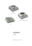
INTRODUCTION
This manualshowsyou how to operateandprovidestechnicaldatafor RealTime Devices'AD2000 multifunctiondata
analog-o-digital
multichanneldifferentialor single-ended
acquisitionboard.The AD2000features12-bithigh-speed
operatein the
to
effectively
your
compatible
computer
PCIKT/AT
or
IBM
interface
allows
versatile
conversion.This
i-l shows
Figure
generate
signals.
analog
digital
and
and
control
to
sense
acquisition
and
of
data
real-timeenvironment
PC
for
a
data
collection.
setup
using
laboraory
a typical
0N
rU0SKSrnrl
[RSORnT0RT
llflf,OtltflRt
tBMPCor
sIrTUf nE
CompEtible
S l g n a lc o n d l t l o n l n gD s c g u i s l t l o nd, o t a r e d u c t l o n ,
grdphlcs,onalgsls,conlrol, data storsge
RUTOHRTION
L R BOERTORT
Fig. i-1 - Typical LaboratorySetup
The AD2000 featuresa high-resolution(12-bit) analog-to-digitaland converter,digital VO, and timer/countersthat
provide flexibility for many applications.Its six-layer construction,including sep:uatepower and ground planes,
It plugsdirectly into anyunusedexpansionslot (shortor fullenhances
boardperformanceandlow-noisecharacteristics.
size)in the computer.All externalI/O connections,includingPC bus-sourcedpower,areaccessibleat therearpanelof
the computerwhen the boardis installed.
Severalof ttreAD2000's functionscanbe readily adaptedfor your specificrequirements.Throughprogrammingand/
or jumper or switch settingsmadeon the board,you can:
. Selectthe baseVO address,
. Choose8 differential or 16 single-endedanaloginput channels,
. Selectthe activechannel,
. Selectthe channelgain,
. Selectthe analoginput voltagerangeandpolarity,
. Conrol 16TTL/CMOS-compatible
digital VO lines,
. Control three l6-bit, 8 MHz timer/countercircuits (theprogrammableinterval timer),
. Monitor theA/D conversionusingtheend-of-convert
(EOC)signal,
. Generateintemrptsignals.
Many of these functions are set up at the factory, basedon typical data collection requirementsand customer
specificationswhenordering.Therefore,you cansuccessfullyinstall andrun theAD2000 with minimal understanding
aboutchangingandcontrolling them.On the otherhand,you may want to understandeverythingahut your boad so
that you caneffectively useeachfeature.With this in mind, this manualprovidesbasicinformationto get theboardup
of eachfunction.
andrunning,aswell asdetailedinformationfor a full understanding
i-1
How to UseThis Manual
Thismanualis designedto helpyouinstallandgetyourAD2000runningquickly,while alsoincludingsufficientdetail
abouteachboardfunction. Begin by readingChapterI in ordero useyour boardasquickly aspossible.This chapter
youto promptlyuseyour
softwareincludedwithyourAD2000packagewillallow
andtheaccompanyingdemonstration
4.
2
Chapter
read
through
5 containsboard
fully
the
AD2000
functions,
Chapters
understandandcontrol
interface.To
procedures.
calibration
The chaptersand appendixesin this manualaredescribedin denil below.
Chapter1, "Quick Start--Geuing Your AD2000 Running," providesthe instructionsnecessaryto
insall theboardanduseits basicfunctions.Theinformationcontainedin this chapterdoesnot cover
how !o changethe boardseurp,exceptfor thebaseICI address.
Chapter2, "Functional Description,"providesa block diagnm and a functional discussionof the
board.
Chapter3, 'Tumper Settings,"describeseachheaderor jumper circuit on the board and how it is
controlled.
Chapter4, "ProgrammingYour AD2000,' describeshow the board canbe programmedusing the
demonstrationsoftware.
Chapter5, "Calibration Procedures,"providesinstructionsfor boardcalibration.
Appendix A, "AD2000 Specifications,"containsa completelisting of boardspecifications.
Appendix B, "ConnectorPin Assignments,"conlainsthe pinous of the externalVO connecorsand
the matingconnectors'part numbers.
Appendix C, 'Component Data She€ts,"contains manufac[rers' data sheetsfor major board
components.
Appendix D, "Configuring the AD2000 for SIGNAL*MATH," containsinformation aboutseuing
boardjumpers and and initializing the board to run the SIGNAL*MATH acquisitionand analysis
program.
Appendix E, "Configuring the AD2000 for ATLANTIS," coniainsinformationaboutsettingboard
jumpersto run the ATLANTIS dataacquisitionandreal-timemonitoringprogram.
Appendix F, "Warranty," containsboardwarrantyinformation.
When You NeedHelp
Whenyou areworking with the AD2000 interfaceboard,this manualandthe demosoftwareincludedin your package
will providesufficientinformationto properlyconnol all of theboard'sfunctions.If, however,aftercarefullyreviewing
fromtheboard,Real
TimeDevices'technicalstaffisreadyoassist
66p'ral,youareunabletoobtainproperresponses
1fus
you. For assistance,call (814) 234-8087during regularbusinesshours,easternstandardtime or easterndaytght time,
to (814) 234-5218.Be sure!o includeyour company'sname,your name,your
or senda FAX requestingassistance
number,
description
of the problem.
anda brief
telephone
i-2
CHAPTER 1
RUNNING
QUICK START_GETTING YOUR AD2OOO
To get startedusingyour AD2000 interfaceboard,you must:
- Selectby jumpera baseI/O addresswhich doesnot contendwith any ottrerperipheraldevice.
- Installtheboardino yourPC.
- Connecta signalto oneofthe analoginputchannels.
- Run the AD2000 software.
Unlessyou haveotherrequirements,thesestepsareall that are necessaryto useyour AD2000 board.
This chapterexplainshow to insrallyoru AD2000anduseits basicfunctions.You will learnhow to:
. Changethe baseVO addresssetring,
. Install the boardin your PC,
. Initialize the board,
. Selectthe analoginput channeland gain,
. Take an A/D reading.
This chapterallows you to immediately start using the basic functions of your AD2000 board for daa collection
applications.This chapterdoesnot explainhow !o controlthemoreintricateboardfunctionssuchastheprogrammable
nordoesitexplainhowto changehardware-controlled
intervaltimer,thevariousdigitalVOconfigurations,orintemrpts,
The
herearedescribedin Chapters2 through4.
I/O
functions
not
covered
seuingsexceptfor the base address.
What ComesWith Your AD2000
The standardAD2000 boardpackageincludes:
1
I
I
AD20005.5-inch (1a0mm)interfaceboard(fits short slot)
AD200Odemodisk
user'smanual
Additional items, suchas the AD2000 2-cableset (order numberXK40-l), extenderboardsor SIGNAL*MATH or
ATLANTIS applicationsoftware,areavailablefor this boardandare includedon an as-orderedbasis.
All signalson your board are madeeasily accessiblewith Real Time Devices' XB40 VO extenderboard and XC40
expansioncable.The extenderboardhastwo 20-pinterminalstripsanda prototypeareato supportany specialcircuitry
you mayrequireto conditionthesignals.For example,if you areprototypingsolid-staterelaysor optoisolalors,this can
easily be done with an XM0. The expansioncable terminatesin a 40-pin wire-wrap headerconnectorsuitablefor
installationin standard0.1 inch spacingperf-boardmaterialavailablefrom mostelectronicdisributors.
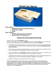
The Hardware
The AD2000 interfaceboard is shownin Figure l-1. A completelisting of the board specificationsis containedin
Appendix A. The AD2000 hasseveralfeatureswhich are user-controlledthroughhardwareor software.Most of the
hardware-controllablefeaturesarejumper-contnolled;theremainingare switch+onnolled.
unusedexpansion
Allofttreboardcomponentsaremountedona5.5-inchprintedcircuitboardwhichfitsinany
slot(short
or full-size) in an IBM PC/XT/AT or compatiblecomputer.Two 4Gpin connectorson the board, P8 and Pl5,
accommodateall of theboard'sextemalI/O. In operation,theseconnectorsarecabledsothat all S0linesareaccessible
at the rearpanelof ttrecomputer(seethe boardinstallationinstructionslater in this chapter).
FunctionsYou Can Set
To allow the AD2000 interfaceboardto be adaptedto your needs,severalfunctionscanbe setup to perform specific
tasksby changingthe hardwareconfigurationor throughsoftware.Table l-1 lists eachfunction you can control, the
facory (or default) settingif applicable,and wherein this manualyou can find informationaboutits settings.
l-l
U L
*-Sy-1lU;tH.t5=
lH
l-.2-r
*
*
;--7=,.
-l
l+
I
-tui=sr
A
-F-"
EIJ=Ff,--d
ru
-r
E?
tP2
:nl
ilc-
12-BitA/D Board
Fig. 1-1 - AD2000 Board Layout
The functionswhich you can control throughhardwareare:
- BaseI/O address,
- Analog input channeltype,
- Analog input channelvoltagerangeandpolarity,
- End-of-convert.
monitor,
- PIT timerrcounters(hardwareand software),
- Intemrpts.
The functionswhich you cancontrol throughsoftwareare:
- Analog input channelselection,
- Analog input gain selection,
- Digital VO,
- PIT timer/counters(softwareand hardware),
- Boardinitialization.
Settingthe BaseVO Address
(BA), theAD2000boarduses
12address
locationsin yourcomputer'sI/O space.Table
Startingwith thebasel/Oaddress
1-2 lists the VO map for the AD2000. It is importantto recognizethat someof your computer'sVO addresslocations
will alreadybe occupiedby internalI/O andotherperipherals.If your AD2000boardtries to useI/O addresslocations
alreadyin useby anotherdevicein your syst€m,addresscontentionwill result.Hence,theboardwill not operate,or at
bestwill operateerratically.
VO addresscontentionis one of the most commonproblemsencounteredwhen adding an interfacedevice to your
By changing
computersystem.Toavoidthisproblem,abaseVOaddrcssjumpercircuitisprovidedontheAD2000board.
the position of thejumper on the headerconnectorlabeledP2 Qocatedjust to the left of center,nearthe botom of the
board),thebaseI/O addresssettingcanbe changedto any oneofeight locations.
L-2
Table 1-1-AD2000 Board Functions and Settlngs
FUNCTION
FACTORY SETTING
USER INFORMATION
Basel/OAddress
300hex(768decimal)
To changethis setting,see
"Settingthe Basel/O
Address,"
Chapter1
AnalogInputChannelType
8 differential
channels
To select16 single-ended
channels,
seeS1 discussion,
Chapter3
AnaloglnputChannel
Selection
lable
Software-control
See "Selectingan Analog
InputChannel,"
Chapter1,
anddemodisk
AnaloglnputGainSelection
lable
Software-control
See"Settingthe InputGain,"
Chapter1, anddemodisk
AnaloglnputVoltageRange
and Polarity
whenordering To changethesesettings,
User-specified
see
51 and P9 discussions,
Chapter3.
-Convert(EOC)Monitor Connectedto PA7
End-of
See P6 discussion,
Chapter3.
Digitall/O
16 l/OLinesfromPPI
lable
Software-control
See"Programming
the PPl,
Chapter4 anddemodisk
Modes
lable
Soflware-control
See"Programming
the PlT,"
Chapter4 anddemodisk
l/O Conliguration
Clocklnput:5MHz
GateInput:+5 V
ClockOutput:To PB
See P3 discussion,
Chapter3
Disabled
See P4,P5,and P7
discussions,
Chapter3, and
"lnterruptConsiderations,"
Chapter4
Inverval
Timer
Programmable
(PlT)Circuitry
Interrupts
l-3
headerconnector,
P2,with thejumperinstalledat thefactory-setlocationof 300
FigureI -2 showsthebaseI/O address
pinsonP2.ThehexadecimalbaseVOaddress
acrossone
of theeightpairsof
hex.Thejumpermustbeinstalledvertically
pins,
pair
from
is
follows:
left to right, as
of
settingconespondingto each
200
240
280
2C0
300
340
380
3C0
listedin Table1-2,BA equals280.
is changedto 280hex,thenfor the 12operations
For example,if thebaseI/O address
Thus,to sendthechannelselectionandgaindatato port B of thePPI,its addressof BA + 1 becomes281 hex.
If thefactorysettingof 300hexwill causecontentionin yoursystem,positionthejumpertothedesiredbaseVOaddress
makea noteof its valueon thetableinsidethebackcoverof thismanual.
setting.OnceyouhavesetthebaseI/O address,
You will needto know this settingfor usein your programs.
g)
N
o
o
o
o
P2
Fig. 1-2 -
Base l/O AddressConnector,P2
Installingthe AD2000in Your Computer
Beforeinstalling the AD2000 in your computer,makesurethat thebaseI/O addresshasbeenproperly selectedandall
how to controlthebase
Thischapterexplains
thehardwaresettingshavebeenconfiguredo supportyourrequirements.
factorysettingsunless
remain
at
their
listed
in
Table
11
are
set
factory,
and
Other
hardware
settings
at
the
as
address.
,
VO
you changethem.The intemrptsgeneratedby your AD2000aredisabled(not connected)whenyou receiveyour board.
If you intendto usetheintemrpts,theymustbeconfiguredappropriately
beforeinstallingtheboard.Informationabout
theseandotherfunctionsnot coveredin this chapteris providedin Chapters2 through4. Usethesechaptersasnecessary
to configureyour boardbeforeinstallation.
To install your AD2000, follow thesestep-by-stepprocedures:
1.TURN OFFTIIE POWERTO YOURCOMPUTERFIRST.Referto theowner'smanualfor your
computer,andremovethe top cover.
2. Selectan unusedexpansionslot (shortor full-size)in which to installyourboardandremoveits
correspondingblank bracketfrom therearpanelof the computerby removingtte screwat the
top of the bracket.
mustbe inslalledon
3. Beforeplacingthe boardinto the computer,two ribboncableassemblies
andPl5.Ifyouhavepurchased
theAD2000cableset,firstinstallthetwisted
boardconnectorsPS
pair cableon analogVO connectorP8.Theninstallthestandardcableon Pl5. Eachcableis a
4Oline externalVO cablewhich extendsthroughthe connectorslot in the rearpanelof the
computer.Both cablesrun througha singleslot wheretheyprovide80lines of externalI/O to
your
I/O throughasingleexpansionportin
allowssubstantialboard
theboard.Thisconfiguration
computer.AppendixB lists the signalcarriedon eachpin of theseconneclors.To install the
cables:
a. Removethestrainrelief clampattachedto theAD2000bracketlocatedon theright sideof
the board.
b. Connectthe socketconnectorto boardconnectorfor eachcable.Wheninstalling,observe
theconnectorkeyingandpressfirmly to makesurethatthesocketconnectoris fully seated
on the board.Each cableprovidedis labeledwith the connector'sP numberfor easy
identification.The cableshavestrainreliefson one connectorandnot on the other.The
connectorwithout the sFainrelief is to be installedon the board.After both cablesare
installedon theboard,positionthemsothattheypassovertheflangein theboard'sbracket.
t-4
Table 1-2-AD2000 l/O Map
FUNCTION
A4
A3
A2
A1
AO
R/W
BA + HEX
PortA
PortB (ChannelSel&Gain)
PortC
ControlWord
0
0
0
0
0
0
0
0
0
0
0
0
0
0
1
1
0
R/W
W
R/W
0
1
2
3
0
0
0
0
0
0
0
0
1
1
1
1
x
x
x
x
0
1
0
1
w
w
R
R
4or6
5 or7
4or6
5or7
1
1
1
1
0
0
0
0
1
1
1
1
0
0
1
1
0
1
0
1
R/W
R/W
R/W
W
14
15
16
17
PPI
1
0
1
w
l/D Conversion
Circuitry
Start12-bitConversion
Start8-bitConversion
ReadMSB
ReadLSB
lntervalTimer
Programmable
Counter0
Counter1
Counter2
ControlWord
NOTE:x = don'tcaresetting
l-5
c. Re-at6chtheclampto thebracketusingthehardwaresuppliedwith your AD2000,securing
the ribbon cablesin place.
4. l.J:tercheckingthat the cablesare correctly installedon the board,orient the board inside the
computerso that thecablesextendthroughtherearpanelopeningandthe cardedgeconnector
lines up with the expansionslot connector.Then,pressdown on the metalbrackettab and the
top of the boarduntil the boardis firmly seatedin the expansionslot connector.
5. Securethe bracketbackin placewith the screwandput the coverback on your computer.
Now your boardis readyto beconnectedvia theexternalconnectorsat therearof thecomputer.After theseconnections
havebeenmade,the boardis readyfor operation.
The Software
The AD2000 operatesunder softwarecontrol. Programmingincludesthe analoginput channelselectionand gain,
control of the the A/D conversion,the programmableperipheralinterface,and the programmableinterval timer. The
analoginput channelandgain selectionsandtakingan A7Dreadingarecoveredin this chapter.Digital I/O control and
control of the programmableinterval timer are more complex,and are de.scribedin Chapter4, "ProgrammingYour
AD2000."
Regardlessof what programminglang"age you use, you can write programstlat conEol the AD2000 board. The
demonstrationdisk which accompaniesyour AD2000 containsexamplesin Turbo C, Turbo Pascal,and BASIC.
Nearly all modernMS-DOS-basedPC languageshaveI/O referenceinstructions.Theseare the insructions to control
thedataransfers to andfrom theI/O ports.Consultyour programminglanguagereferenceto find theseinstnrctionsfor
your favorite language.Listed below are the VO referenceinstructionsusedby somecommonlanguages.
BASIC
input:
output:
INP
OUT
TURBO PASCAL
Port
Port
TURBOC
inportb
ouQortb
DemoDisk
Included with your AD2000 is a demo disk which providesprogramminginstructionsand exampleprogramsfor
controlling the functionsof your interfaceboard.This demodisk is divided ino directories,eachof which is named
accordingto the languageusedto write 0re programsit contains.The files within eachdirectory coniain example
programsanda documentationfile witi generalinformation.In addition,your demodisk containsa README.DOC
file which providesprogramminginformation for your board.
Eachexampleprogxamshowsyou how to controla particularboardfunction,suchasselectingan input channelor input
gain, controlling the A/D converter,controlling digital data Eansfers,and seuing the timer/countercircuitry. These
programsshouldbe usedto becomefamiliar with thesefunctions.
Backing Up Your Disk
Thedemodisk providedwith theAD2000is a double-sidedformatwhich canbereadby all DOSversions1.1andabove.
Beforeusingthe softwareincludedwith your board,makea backupcopy of thedisk. You may makeasmanybackups
as you need.To copy the original to any other DOS-formatteddisk, insert the disk o be copiedinto drive A of your
computer,and from DOS enter:
COPY A:*.* B: (or otherdestinationdrive specifier)
l-6
Initializing Your AD2000
BeforeyoucanoperatetheAD2000,it mustbe initialized.This stepmustbe executedeverytime you startup,reset,or
rebootthecomput€r.This setsup thePPI to properlycommunicate
with theA,/Dconvertercircuitry.If theboardis not
initialized,it will notrespondto thesoftwarecommands
andwill probablylock up,requiringyouto rebootyoursystem.
As describedearlier,theAD2000uses12addresslocationsin thecomputer'sI/O space,Theseaddresslocationsstart
with tle baseI/O address(BA) andgo throughBA + 17(hex).BA + 8 throughBA + 13arenotused.Tablel-2 provides
is factorytheAD2000I/Omap,definingwhatfunctioneachof the12addresses
controls.RecallthatthebaseI/O address
setat 300 hex.On thedemodisk, thebaseI/O addressis usuallystoredin thevariable"board."Rememberto usetlre
correctbaseVO addressin tle demodisk programsor yourown programs.Thedemodisk explainshow to changethe
baseI/O addressin the programs.
The AD2000 is inirialized by simply writing a control byte lo the PPI control registermappedat the VO locationbase
address+ 3 (hex).The conrol bytemustconformto this generalform:
lxxx x00x wherex =don'tcare
This ensuresthatthe eightI/O linesmakingup port B of thePPI,which areusedto controlthe multiplexerand gain
circuitry,areconfiguredasoutputs.Thedon'tcare(x) positionscontrolthedirectionof theremaining16digitalI/O lines
availableon thePPI.Theselinescanbe confrguredasinputs,outputs,or in othermorecomplexconfigurations.
For example,whenthecontrolbytebit patternis:
100000000 (decimal128)
the AD2000 is initialized as follows:
out base_address+3,
I 28
Whenthisvalueis usedto initializetheAD2000,theeightport C linesof thePPIwill all be configuredasoutputs.You
cantransferdatato theselineswith thecommand:
out base_ad&ess+2,data
If instead,thedecimalvalue137(10001001)is usedto initializetheAD2000,theport C lineswill be setup asinputs.
You caninput datafrom port C with the command:
data= inp(base_address+2)
Note thatport A, bit 7 (PA7) of the PPI is factory-setto monitorthe end-of-convert(EOC)signal.The PPI mustbe
programmedso thatport A is an inputif you aregoingto monitortheEOC signalthroughPA7. Theconnolbyte must
thenconformto thegeneralform of lxx! x00x,wheretheunderlinedI is thedatabit which setsup port A asaninput.
Description,"andhardwareconfigurations
A functionaldescriptionof thePPIis containedin Chapter2,'Functional
are
describedin Chapter3, "JumperSettings."Informationabouthow you cancontrolthediginl I/O linesis containedin
Chapter4, "ProgrammingYour AD2000,"andis not coveredherebecauseof its complexity.
As mentionedearlier,theeightlinesof port B areusedto selecttheanaloginputchannelandgain.The four LSBs,PB
(forPortB) 0 throughPB3,controlthechannel
selection,andthe
fourMSBs,PB4throughPBT,control
thegainselection.
Thebit assignment
of thisport is:
t-'7
MSBs
7654
LSBs
3210
\-rJ
+.-'
P P IP o r t B ( B a s e A d d r e s s + 1 )
gainselect
channelselect
0000= 1x
0001= 2x
0 0 1 0= 4 x
0100= 8x
1 0 0 0= 1 6 x
0000= channel1
0001= channel2
0010
0011
0100
0 10 1
0 11 0
0111
1000
1001
1010
1 0 11
11 0 0
11 0 1
1 1 1 0= c h a n n e1l5
1 1 1 1= c h a n n e1l6
After theAD2000 is initialized, theport B registeris loadedwith thedefaultsettingof 00000000.This selectschannel
I as the input channelwith a gainof 1. To changethis value,for example,lo a gain of2x on channel16,enterthese
commands:
BA + I (hex)
selectsport B
0001 1111
sesgainto2xandchannelo
16
Recallthattheboard'sdefaultchannelsettingis eightdifferentialchannels.Therefore,only the channelselectbinary
valuesforchannelsI through8 apply.Channels9 through16areusedin thesingle-ended
channelmodeonly.
Now yourboardisinitializedandready
ooperate.Thefollowingsectionsdescribehow
toselecttheanaloginputchannel,
setthe input gain,and takean A/D reading.Masteringtheseoperationswill allow you to effectively useyour boardfor
dataacquisitionapplications.
Selectingan Analog Input Channel
After theAD2000hasbeeninitializedyou canselecttheanaloginputchannel.Theanaloginputchannelis selectedby
writing !o port B of the PPI, mappedat I/O locationbaseaddress(BA) + 1.
The inputchannelandtheinputgaincanbe setindividuallyby settingonly thefour LSBs (channelselect)or only the
four MSBs Gain) of tie eight-bitcontrolword sentto port B. Beforeyou changeeitherthe input channelor thegain,
you MUST preservetle currentstateof port B. Failure trodo so will resultin changingboth the channelselectandthe
gainwhenyou intendedo changeonly oneof thesetwo settings.
just thefourLSBsof thecontrolwordwhilepreservingthefour
Thegeneralalgorithmfor settingtlechannel(changing
MSBs)is:
l-8
1. Readthecurrentstateof port B:
curent_state= inpoase_address+1)
2. Preservetheupperfour bits sincetheycontaingaindata:
current_s[ate= current-slateAND $F0
with thedesiredchannelnumberminus 1:
3. LogicallyOR thecurrent_state
=
curenr-state curent_stateOR (channel- l)
4. Write it backout to port B:
l,current_state
out base_address+
A BASIC programto selectchannel2 is:
= 768
100BASE-ADDRESSTo
=2
110CHANNELVo
=
+ l)
120STATUSTo INP(BASE-ADDRESSTo
130STATUSTo= STATUSToAND &HFO
140STATUSTo= STATUSToOR (CHANNELTo-l)
+ I,STATUSTo
150OUT BASE-ADDRESSTo
Settingthe Input Gain
Thegainis setbywritingtotheupperfourbitsofportBatBA + l. Thebitpatternforeachof thefivegainvaluessupported
by the hardwareare:
0000 = gain of I
0001= gainof2
0010= gainof 4
0100= gainof 8
1000= gainof 16
It is recommendedthat no otherbit patternsbe usedwhen settingthe gain.
The generalalgorithm for settingthe gain is:
1. Readthecurrentstateof port B:
1)
current-state= inp(base_address+
2. heserve the lower four bits sincetheycontainchannelinformation:
= CUrrg[t-StateAND $0F
current-sCate
3. Ingically OR thecurent_statewith a bit pattemthatactivatesthedesiredgain:
oR gain bit pattern:
current_state= currgnt_State
lx bit pattern= 0
2x bitpattern= 16
4x bit pauern= 32
8x bit Pattern= 64
l6xbitpattern= 128
4. Write the current_stateback to port B:
l,current-state
out base_addrcss+
r-9
A BASIC programto seta gainof 2 is:
= 768
100BASE-ADDRESSTo
110GAINTo= 2
+ l)
120STATUSTo= INP(BASE-ADDRESSTo
130STATUSTo= STATUSToAND &H0F
140IF GAINTo= I GOTO 160
150STATUSTo= STATUSToOR (GAINTo* 8)
+I,STATUS7o
160OUT BASE-ADDRESSTo
Taking an A/D Reading
After you haveselectedan analoginput channeland setthe gain, you can takean A/D reading.It is importantto note
thatoncethegainandchannelareset,theystayat thosesettingsuntil you changethem;thatis, theyarelatched.You
do not haveto setthe gain or channelevery time you takea reading.
Eachtime an A/D conversionis completed,an end-of-convert(EOC) signalis generatedto signify the end of the
Thissignalcanbeusedinanumberofways.Onewayis to usethislineto monitortheAlDconversionstatus.
conversion.
ofPPlportAorportC asaninputlineandconnecting
signalobe monitoredinvolvesconfiguringbitT
SeninguptheEOC
theE@ signalto it. This procedureis detailedin Chapter3,'TumperSettings."The EOC signalis factory-setto be
monitoredthroughPA7 on headerconnectorP6.
The generalalgorithm for taking an A/D readingis:
+ 4 (or 6):
1. Starta l2-bitconversionby writing o base-address
out base-address+4,0
(Note that the valueyou sendis not important.The act of writing to this I/O location is the key
to startinga conversion.)
or monitorPPI port A or C, bit 7 for a transition.Polling
2.Delay at least20 microseconds
permits the fastestdataacquisition.
+ 5 (or 7):
3. Readtheleastsignificantbit from base-address
-+5)
lsb%o inp(base-address%o
+ 4 (or 6):
4. Readthemostsignificantbit from base_address
=
+4)
msbTo inp(base-address7o
result
into
ttre
12-bit
by shiftingtheLSB four bits o theright. The MSB must
them
5. Combine
alsobe weightedconectly:
resultVo- (msb7o* 16) + (lsb7ol16)
For a l2-bit conversion,the A/D datareadis left justified in a l6-bit word,with theleastsignificantfour bis equalto
of ttris,thetwobytesof A7Ddatareadmustbescaledto obtaina validA/D reading.
zero,asshownin Figurel-3. Because
Onceit is calculated,thereadingcanbecorrelatedlo a voltagevalueby scalingit, in thecaseof bipolarinputranges(t5
bit weight,asshownin thetableat thetopof thefollowingpage:
or +10 volts),andthenmultiplyingby theappropriate
MSB
D15 014
D13 D12 D11
D10
D9
D8
D7
D6
D5
D4
D B 1 2DB11 D B l O D89 D88 D87 D86 D85 D84 D83 D82 DB1
Fig.1-3- A/D Conversion
WordFormat
l-10
D3
D2
D1
LSB
DO
0
0
0
0
Input Range
+5 volts
+10 volts
0 to +10 volts
ScaleFactor
Subtract
2M8
Subnact2048
None
Bit Weight
2.4414mY
4.8828mV
2.4414mY
For example,if theA/D readingis 1024andthe inputrangeusedis *5 volts,theanaloginput voltageis calculatedas
follows:
00z. - 2&18)bits * 2.4414mv/bit = -2.49999volif,.
For a tlO volt input range,the voltageis calculatedasfollows:
(l0U - 2048)bits * 4.8828mv/bit = -4.99999volts.
For a 0 to +10 volt inputrange,no scalingis requiredandthe voltageis calculatedasfollows:
1024birs * 2.4414mV/bit = 2.49999volrs.
The input voltagerangeandpolarity arefactory-setaccordingto customerspecificationswhen orderingthe board.Il
youwishtochangetheinputvoltage,seeChapter3,'TumperSettings."Wheneverthevoltage
afterreceivingyourboard,
polarity is changed(unipolarto bipolaror vice versa),theA/D convertershouldberecalibratedasdescribedin Chapter
5, "Calibrationhocedures."
canalsobeperformed.This is accomplished
by writing to I/O locationBA + 5 (or
Notethateight-bitA/t) conversions
7). While aneight-bitconversionhasa lowerresolutionthanthe 12-bitconversion,it is performedmuchmorerapidly,
youcan
A 12-bitconversion
Therefore,whenspeedis essential,
takesabout20
microseconds.
in about13microseconds.
usetheeight-bitconversioncapability.
t-11
CHAPTER 2
FUNCTIONALDESCRIPTION
Figure2-1showsablockdiagnm of ttteboard.
themajorfunctionsof theAD2000interfaceboard.
Thischapterdescribes
The functionsdiscussedin the following sectionsare:
. Analog-to-digitalconversioncircuiry
. Programmableperipheralinterface(PPI) circuiry
. Programmableinterval timer (PIT) circuitry
Analog-to-DigitalConversionCircuitry
The main function of the AD2000 interfaceboardis to provide high-speedanalog+odigital conversioncapability for
dataacquisition.The analog-to-digital(AlD) conversioncircuitry receivesinpus from eight differential or 16 singleconversionof thevoltagevalueread
ananalog-to-digital
andperforms
selectsoneactivechannel,
endedanalogchannels,
at that channel.The conversionthroughputrateis typically 38 kIIz.
Multiplexers
Two eight-bit analogmultiplexersareusedto connecteitheroneof 16 single-endedor one of eight differential analog
channelso the gain circuiry. The leftmostthreeswitcheson DIP swirchS1 setup themultiplexerat IC locationU9 !o
receiveeither single-endedor differential inputs.Whenthesethreeswitchesare up, the multiplexer is configuredfor
single-endedinputs,andwhentheyaredown, themultiplexeris configuredfor differential inputs.Note thatthesethree
swirchesare alwayssetas a gloup to the sameposition(see"Sl SwitchSettings,"Chapter3). A channelis selected
throughsoftwarecontrol, by writing to port B of the PPI, asdescribedin Chapterl.
16AilAlG NruTS
€V TO+$r
0 TO+10\,
-'l0VTO+t0V
tlFF./ t5 s.t
BlockDiagram
Fig.2-1- AD2000Functional
2-l
Gain Control Circuitry
gaincontrolcircuiry canprovideagainfactorof 1,2,4,8,or 16.Thegainselectionis madeby writing
Theprogrammable
port
B
PPI,
to
of the
asdescribedin Chapter1. The gain facor is conrolled by the settingof four analogswitches.For
16,
thiswriteoperationwill closeoneof thefourswitches;foragain factorof 1,all switchesareopen.
againof2,4,8, or
programming
gain facors other tlnn the five listed hereis not recommended.
Note that
Sampleand Hold Circuitry
A sampleand hold (SAD amplifier is usedbenveenthe gain control circuiry output and tlte A/D input to ensurethat
dynamicanalogsignalsareaccuratelydigitizedby theA/D converter.The .001pF hold capacitorusedin this circuit is
apolystyrenetypeselectedfor is low dielecnicabsorption.Its low valueminimizestheacquisitiontime (6 microseconds,
theEOCsignal
stepvoltageanddroop.Thesampleandholdtimeandratearedeterminedby
typical),andminimizeshold
generatedby the A/D converterand fed backinto the SAI circuir WhentheEOC signalis high (logic 1), the amplifier
samplesthe analoginpuq when the EOC signalis low (logic 0), the amplifier holdsthe inpur
A"/DConverter
in approximately
20 microseconds.
l2-bit conversionIC whichperformsconversions
TheA/D converteris a high-speed
Eight-bit conversionscanalsobe performedwhenspeedis morecritical thanresolution.An eight-bit conversiontakes
about 13 microseconds,allowing rapid conversionsof dynamicanaloginputs.The convertersupports10- or 20-volt
analoginput signals;however,it cannotsupporta 20-volt unipolarinputrangebecauseits supplyvoltagein theAD2000
applicationis only +12 volts. The analoginput voltagenmgessupportedby the AD2000 arelisted in the specifications
in AppendixA. Calibrationcircuiry is includedfor unipolarandbipolar calibrationof the A/D converter.Calibration
proceduresaredescribedin Chapter5.
An 8- or 12-bitconversionis initiatedby a write operationto theappropfutelO address.Oncea conversionis begun,
the conversionstatuscanbe monitoredby readingthe AID converterstatus(STS)signalwhich is ouput from the A/D
converterIC andinvertedbeforebeingmadeavailableto othercircuitry on theboardasttteend-of-convert@OC)signal.
The EOC signal canbe monitoredby one of nro digital input lines on the PPI, PA7 or PC7. Note that if either line is
selectedasthe EOC monitor, a jumper mustbe installedfor the selectedline on P6 andthat line mustbe configuredas
an input. The EOC signalis factory-setto be monitoredthroughPA7 on P6. The EOC signalis low (logic 0) during a
A/D outputbuffersremainin a highconversion.Figure 2-2 showsthe EOC timing diagram.Also, the three-state
Whileaconversion
is inprogress,
anytransitionsof thedigitalinpus
impedance
state,and,therefore,datacannotberead.
Once
cannotbeprematurelyterminatedor restarted.
whichcontroltheconversionwill beignored,sothattheconversion
theconversionis complete@OCis now high,or logic 1),theA/D datacanbereadin two bytes,theMSB andtheLSB,
the
in anyorder.Fora l2-bitconvenion,tie dataisleft-justifiedin a l6-bit word.In thecaseof aneight-bitconversion,
datais completelycontainedin theeight-bitMSB.
Referto Chapterl, "Taking an A/D Reading,"andthe demodisk for moreinformationaboutusingthe AID converter.
A/Dcs
tl
Eoc-
v
fi-
r---,
Data
14
Fig.2-2-EOC TimingDiagram
aa
ProgrammablePeripheralfnterface
The hogrammablePeripheralInterface@PI) provides16TTL/CMOS digital VO lines which canbe configuredin a
numberof waysto supportuserrequirements.Thelinesavailablefor digital I/O areport A andport C. The8255PPI has
antalof 24 digitalI/O lines,eightof whichareusedto connoltheA/D channelselectionandgaincircuiry, andtherefore
arenotavailableto theuser.Theremaining16linesareavailableatextemalVO connecorPl5. The24linesaregrouped
into threeeight-bit ports,port A, port B, and port C. Port C is further suMivided into two four-bit ports,port C lower
(PC0-PC3)andport C upper(PC4-PC7)in certainmodesof operation.The PPI datasheetis includedin Appendix C.
The eight bits ofport B arereservedfor A/D channelselectionandgain control, andcannotbe configuredfor I/O use.
PortsA and C can be configuredin any of the threeoperatingmodesdescribedbelow:
Mode 0 - Basic input/outpur Providessimple input and output operat"ions
for eachport. Data is
written to or readfrom a specifiedport.
Mode I - Srobed inpuUoutput.Providesa meansfor transferringlO datzto or from port A or port
B in conjunctionwith strobesor handshaking
signals.
-Suobedbidirectional
input/output.Providesabidirectionalmeansof communicating
with
Mode2
signalsaresimilarto mode1.Thismodeapplies
anotherdeviceon a singleeight-bitbus.Handshaking
to port A only.
In mode0, all four ports (A, B, C lower, andC upper)areavailableasVO lines. Sixteenconfigurationsarepossiblein
tlfs mode,andanyportcanbeconfiguredasaninputoranoutput.Theouputsarelarched,buttheinpusarenotlarched.
In modeI , thefour portsaregfoupedinto two groups.Eachgrcupcontainsoneeight-bitdataport (port A or port B) and
onefour-bit control/dataport (port C lower or port C upper)which is usedfor controlandstatusof theeight-bitport. The
eight-bit dataport in eachgroup canbe configuredasan input or an outpul Both inputsand outputsare latched.
In mode2, port A is an eight-bitbidirectionalbusandport C is a five-bit controlport PortB cannotbeusedin this mode,
but is availablefor usein mode0 or modeI while port A is in mode2. Both inputsandoutputsarelarched.
The PPI is configuredby writing a control word to the appropriateVO addresslocation, as describedin Chapter4,
"ProgrammingYour AD2000."
The control word canalsobe usedto individually setor resettheport C bis. This featureallows any bit of port C to be
setor resetwithout affecting the otherport C bits. The datasheetincludedin Appendix C explainsthis feature.
ThePPIcanalsobeusedo generateinterupts
in modeI or mode2operation.Inthesemodes,theintemrptenable
(INTE)
maskis usedto enabletheINTRA andINTRB interruptsignals.NotettrattheINTRB signalfor PPIcannotbe usedsince
portB of thisPPIis alwaysconfiguredasmode0 outputandis reservedfor channelselectionandgaincontrol.Intemrpt
functionsare further explainedin the datasheetin AppendixC.
The AD2000 boardprovidesa headerconnectorwhich canjumper the A/D converterend-of-convert(EOC) signal!o
a PPI bit whereit canbe monitoredto provide A/D conversionstatus.The EOC signalcanbejumperedto eitherPA7
(portA, bit 7) or PC7(portC, bit 7). Thedefaultsettingof thejumperis PA7.Theport usedto moni[orttreEOC signal
mustbe configuredasa mode0 input port.
ProgrammableInterval Timer (PIT)
Theprogrammable
intervaltimer@IT) canbe configuredfor a varietyof timingandcountingfunctions.This versatile
IC containsthreeindependently
clockedl6-bit timer/countercircuis, TC0, TCl, and TC2, which operateas down
counters.Thesedown counterscanresolvetime incrementsdown to 125nanoseconds.
This circuit's mostcommon
applicationis to provide accuratetime delaysunder softwarecontrol. Upon command,the PIT can count out a
programmeddelay
whenithasfinisheditstasks.All threecounteroutputsarebroughtouttoexternal
andinterruptthePC
I/O connectorP15.
The three16-bittimer/counters
areeachloadedby two one-bytewrite operationsto the appropriateI/O location.fire
wheretheyarestoreduntil thecountsequence
bytesarelatchedintoa l6-bit internalcountregister,
starts.Thecountdown
stafiswhenthecountregistercontentsaretransferred(in parallel)to thedowncounter.The timer/countercircuitscan
be programmedfor binaryor BCD countdowns.
2-3
A 5 MlIz crystaloscillatoron the AD2000 canbe usedto clock any timer/countercircuit Or, the timer/countercanbe
clockedbyasourceexternalto theboardthroughexternalVO connectorPl5.Ratesof dc to 8 MIIzcan beusedaoclock
thetimerrcounters.
Eachtimer/countercanbe configuredfor oneof six modesof operation.Thesemodesare:
Mode0 - Interrupton endof count.TheOUT signalchangesfrom low to highwhentltecountdown
is completed.
one-shot.A low-levelpulseriggeredby theGT inputis outputon theOUT
Mode1- Re-triggerable
pin.
Mode2-Rategenerator.
Mode 3 - Squarewavegenerator.
Mode 4 - Sofnrare-triggeredstrobe.
Mode 5 - Hardware-triggeredstrobe(re-triggerable).
aswell asthecounttype(binaryor BCD),read/writemode,andcounter/timerselection
Thetimer/countercountmodes,
mode,areall part of the control word which is written o the PIT control registerto initialize tle circuir When the PC
is poweredup, thetimer/countercircuits arenot defineduntil theappropriatecontrolwordsarewritten to thecircuits !o
programthemforoperation.Initializationisrequired
Detailedinformation
onlyonceafterapower-upresetoccurs.
about
thePIT, including theconnol word format,is given in thedatasheetin AppendixC. AppendixD containsprogramming
notesfor somePIT applications.
The threetimerrcountercircuifs areindependent.However,they canbe cascadedfor countdownswhich arelongertlnn
to TCI's CK signal,andTCl's OUT
one 16bit field cansupporLFor example,TCO'SOUT signalcanbe connected
signal can be connectedto TC2's CK signal.When configuredttris way, the PIT can accommodateextremelylong
countdowns.This configurationis describedin the applicationnotesin Appendix D.
Oneof the threetimer/counteroutputs,TCOOUT, TCI OUT, or TC2 OUT, canalsobe usedasa PC intemrpt. These
signalsarebroughtout to boardheaderconnectorP5whereone(andonly one)canbe.selectedfor connertion[o anyone
IRQ channel,RQ2 throughIRQ7. Chapter3, "JumperSettings,"and Chapter4, "ProgrammingYour AD2000,"
describetheseintemrptsin moredetail.
24
CHAPTER 3
JUMPERSETTINGS
You
Thischapterdescribes
theAD2000boardsettingsyoucancontrolon DIP switchSI andvariousheaderconnectors.
your
it
or
your
installing
in
computer,
your
functions
before
board's
to
specificapplication
canusethischapterto tailor
you
will
features.
In
you
special
this
chapter,
learn
more
its
about.
operation
and
to changetheboard'sconfigurationas
leamabouteachsettingandhowto setswitchesor installjumpersto achievethedesiredoperationof yourboard.Before
changingany settings,you shouldhavea functionalknowledgeof the circuit you are settingup (seeChapter2).
in thischapterhavebeenfaclory-set,or, asin thecaseof theintemrptsignals,
Remember
thatall of thesettingsdescribed
you
not
have
to
do any furtherset-upof ttreboardin orderfor it to operatein your system
aredisabled.Therefore, do
in
in
1.
The
descriptions thischapterallow you to changefactorysettings,or to tailor your board
asdescribed Chapter
full
its
advantage
of built-in versatility.
to take
ThereareoneDIP switchandseveralheaderconnectorswhich allow you to controlvariousboardfunctions.Theseare
asfollows:
shownin theboardlayoutof Figure3-l andarepresented
Sl * AnalogInput SignalType DIP Switch
P2 - BaseI/O AddressHeaderConnector
P3 - ProgrammableInterval Timer (PIT) I/O HeaderConnector
P4, P5, andP7 - Intemrpt HeaderConnectors
P6 - Endof-Convert(EOC)Monitor HeaderConnector
W - A/D ConverterVoltageRangeHeaderConnector
H,H'Flffiffif
\
I
WPE
POL
CA
G
Y r 6 . \ t
l"ll-li
lll l:;rTld
t
=Jll |;r-"nf
llUilc
pqr (-)c,.
Yl,*jB?."?.
Fig.3-1- 4D2000BoardLayoul
3-1
51 - AnalogInput SignalType DIP Switch
or differentialinputsandselectsa
DIP switchSl, shownin Figure3-2,configuresthe multiplexersfor single-ended
unipolaror bipolarinput volage range.The fint threeswitcheson Sl operateasa group.Whenthesearein the UP
position,themultiplexersareconfiguredfor single-ended
inpus; whentheyarein theDOWNposition,themultiplexers
areconfiguredfor differentialinputs.Notethatthesethreeswitchesmustall be setto thesameposition(UP or DOWN)
for the multiplexersto functionproperly.Theremainingswitch,Sl-4, controlsthe input voltagepolarity.Whenthis
switchis in theUP position,theinputvoltagerangeis unipolar;whenit is in theDOWN position,thevoltagerangeis
theanaloginput
bipolar.This switch,coupledwith thevoltagerangeselectionseton headerconnectorP9,determines
voltagessupportedby theAID converter.Notethatwheneverthepolarily is changed,theAID convertercircuitry should
be calibratedas describedin Chapter5. The switch settingsareclearly labeledon the board to eliminateerrorswhen
configuringS1.
TYPE
POL
1
S.E.
DIFF.
NNEE
+l-
Fig.3-2 -
DIP SwitchSl
P2 - BaseVO AddressHeader Connector
HeaderconnectorP2 controlsttre 12 computerI/O addresslocationsusedby the board.The baseVO addresslocation
is factory-setto 300hex
is setby jumperingoneof theeightpositionson theP2 headerconnector.ThebaseI/O address
(768decimal),wittr thejumper installedacrossthepair of pins fifth from theleft on theconnector.ThebaseI/O address
seuingis fully explainedin Chapter1,"BaseI/O AddressSetting,"andis not repeatedhere.Note theimportanceof this
contentionwith otherdevicesin yourcomputer.Be sureto examinethis
seningwith respectto thepossibilityof address
possibility if you experienceboardfailure when you first auempt!o operatetheboardin your computer.
P3 - ProgrammableInterval Timer (PIT) VO HeaderConnector
intervaltimer @IT). The PIT containsthree
HeaderconnectorP3, shownin Figure3-3, controlsthe programmable
independentl6-bit timer/countercircuits,asdescribedin Chapter2. Eachtimer/counterhasthreeVO signalsassociated
witlr iu a clock, a gats,andan output.P3 canbe configuredin a numberof waysto providemaximumversatilityin
applying this deviceto your particularapplication.Eachtimerrcounteris factory-setfor XTAL clock input, +5V gate
input,andCO output.Figure3-4 showsa block diagramof thePIT.
For easein configuringthis circuitry,the headerconnectoris partitionedinto threefunctionalgroups:TCO,TCl, and
2, respectively.Thesedesignations
also
0, timer/counter1, andtimer/counter
TC2, whichconespondto timer/counter
asshownon thedatasheetincludedin AppendixC. Sarting from the
designations,
correspondto the manufacturer's
top of P3, the first groupof pins on theright sidearelabeledCK0, GTO,andOUTO,the threeI/O signatsfor TCO.The
signalson theleft sidefor TCOarelabeledXTAL, ECO,+5V, EGO,CO0,andC-O0(thissignalhasa barovertop of the
signalnameon theboardastheinversedesigration).Thegroupsof signalsfor TC 1andTC2 areidenticalto TCO,except
that eachhasa CK input on the left sideof the headerconnector.Note thateachsignalnameon the right sideof the
connector(CK, GT, andOUT) spansa groupof two or threepins.Eachgroupcanhaveonly onejumperinstalledat any
describehow thesesignalscanbe usedin thePIT circuit.An "x" is usedin placeof 0,
time.Thefollowing paragraphs
1, or 2 in thesignalnameswheneverthe applicationcanbe appliedto any or all of thethreetimer/countercircuits.
3-2
ls
XTAL
EC0
ls
+5V
EGO
ls
ls
co0
cTo
cK1
XTAL
EC1
+5V
EG1
l3
l:
col
co1
cK2
ls
ls
XTAL
EC2
+5V
EG2
ls
c02
c02
Fig.3-3 -
PIT l/O HeaderConnectorP3
Counter Inputs:
XTAL - This input to all threetimer/countercircuits is from the 5 MlIz crystaloscillator,labeledYl, locatedin the
upperleftareaoftheboard.By connectingXTAL to theCKxinputontherightsideof theconnectorwithajumperplaced
horizontallybetweenthe pins, the 5 MHz clock is appliedto the timer/countercircuit. If requiredby your application,
theXTAL frequencycanbe changedby installinga differentcrystaloscillaor at Y I . Note, however,that themaximum
frequencyat which the PIT will operateis 8 MHz.
ECx-This inputallowsanexternalclock,otherthantheXTAL signal,to controlthetimingof thecorresponding
timer/
countercircuir This pin canbe horizonally jumperedto theCKx input on theright sideof theconnector,in placeof the
XTAL souce. The ECx signals are brought onto the board through externalVO connectorPl5 (seeTable B-3 in
AppendixB).
GateInputs:
+5V - This input, if connectedo theGTx input by placinga jumperhorizontallybetweenthe two pins,placesthe
associatedtimer/countercircuit in an enabledstateat all times.
EGx -This inputcanbehorizontallyjumperedto theGTx inputontherightsideof theconnector!oprovideanextemal
gateinputinsteadof the+5 volts input TheEGx signalsarebroughtontotheboardthroughexternalVO connectorPl5
(seeTableB-3 in AppendixB).
CounterOutputs:
COx - This output canbe horizontallyjumperedto the correspondingOUT pin on the right sideof the connectorso
that theclock outputsignalcanbe routedto externalI/O connectorP15(seeTableB-3 in AppendixB).
CO" - This outputcanbe horizonallyjumperedto thecorrosponding
OUT pin on theright sidoof the connectorto
providetheinverseof theclock outputsignalto externalI/O connectorPl5(seeTableB-3 in AppendixB).
3-3
CKx - This input connectstheoutputof onetimer/counterto theclock input of thenexttimer&ounter.CKx is provided
for TCl andTC2 only, andis connecM to theoutputof theprevioustimer/counter(tCO or TCI) by placinga jumper
horizontallybetweenthepins.Theseconnectionsareusedto cascadethe timer/countersfor longertime delaysthanare
supportedby a single timer/countercircuit.
P3
P15
8255PtT
U5
*ro1--klEC0
*sv---Id
t)o
EGO
<d
co0
c-ool
o
cKll I
XTALI
EC1
+sv-aQ
EG1
co1
<------rc
co1lo
XTALIO
t>o
EC2
..5y-€
EG2
co2
{-O
.4,
to'r-u
Fig. 3-4 -
PIT FunctionalBlock Diagram
P4.P5. and P? - Interrupt HeaderConnectors
HeaderconnectorsP4, P5, and F7 are usedto jumper varioussignalsgeneratedby the AD2000 circuitry !o the PC's
interruptchannels.Theintemrptchannelsavailableon theboardareIRQ2 throughIRQ7.Note thatonly oneintemrpt
in thecomputersystemcanbe connectedto an intemrptchannelat any giventime.
Beforeattemptingto useintemrpts,you shouldbe familiar with theprocedurefor initializing the intemrpt vectorsand
thePC's interruptcontroller,andsettingup theintemrpthandlingroutines.Theseprocedures
arebeyondthe scopeof
this manual,but mustbe understoodo effectivelyuseintemrptsin you computersysiem.
Be carefulto avoid contentionwhenselectingthe intemrptchannelsused,both with the signalson the AD2000 aswell
aswith otherdeviceswithin your computer.To avoidcontention,usethetableinsidethebackcoverof this manualto
recordttreintemrptchannelsyou usewith theAD2000board.
It is alsovery importantto notethat theAD2000intemrptsourcesareTTL totem-pole(push/pull)typeoutputs;they are
Therefore,do not att€mptto connectoneof theseintemrpb to any otherintemrptoutput.
not open-collector.
The following paragraphsdescribethe interruptsavailableon your AD2000 board.
34
P4 - EXTINT and PPI INTRA Interrupts
is usedto selectEXTINTorPPIINTRA for connectionto oneof thecomputer'sintemtptchannels
HeaderconnectorP4
IRQ2 throughIRQ7. EXTINT is providedto accommodatean interrupt signalgeneratedexternalto the AD2000 and
routedontotheboardthroughexternalI/O connectorP15(seeTableB-3 in AppendixB). PPI INTRA (labeledPC3on
duringPPImode1or mode2 operationonly.Oneof these
by thePPI.Thisintenuptis generated
theboard)is generated
IRQ2 throughIRQTby firstplacinga
two signalscanbejumperedto oneof theavailablecomputerintemrptchannels
jumperverticallyacrossttrepinsof thesignalchosenandthenplacinga secondjumperverticallyacrossthepinsof the
to
selectedIRQ channel.Figure3-5 showsheaderconnectorP4with jumpersinstalledsothatPPIINTRA is connected
RQ2.
F
z
IRQ
(
o
t
)st
I\
ul o.
FGI
xc)
P4
Fig. 3-5 -
Interupt HeaderConnectorP4
P5 - PIT Output Interrupts
HeaderconnectorP5, shownin Figure3-6,is usedto jumperoneof thethreePIT outputs,OUT0,OUTI, or OUT2,to
oneof thecomputer'sintemrptchannelsIRQ2 throughIRQ7.As in the caseof P4, two jumpersmustbe installedto
First,installajumperhorizontallyacrossthepinsof thePlTouput selected.
connectaPlToutputto aninterruptchannel.
Figure3-6showsjumpeninstalledsothat
thepinsof theintemrptchannelselected.
Theninstallasecondjumperacross
OUT2 is connectedto IRQ3.
7
6
5
4
3
2
P5
ol
118
21-{
Fig.3-6 -
InterruptHeaderConnectorP5
Yl - ND End-of-Convert(EOC)Interrupt
(EOC)signalto one
HeaderconnectorP7, shownin Figure3-7,is usedto jumpertheA/D converter'send-of-convert
to an RQ channelby installing
of thecomputer'sintemrptchannelsIRQ2throughIRQ7.TheEOCsignalis connected
Figure3-7 showstheEOC signalconnected
a singlejumperhorizontallyacrossthepins of theIRQ channelselected.
ro IRQ4.
3-5
7
6
5:0
4o
3
2
Fig. 3-7 -
InterruptHeaderConnectorP7
P6 - End-of-Convert(EOC)Monitor HeaderConnector
As describedabove,the A/D converterend-of-convert@OC) signalcanbe usedto generatean intemrpL If this signal
isnotusedasanintemrpt,itcanbeusedasastatusmonitoroftheA/Dconversionprocess.
HeaderconnectorP6provides
twolinesthroughwhich
tleEOCcanbemonitoredfromthePPI,PATorPCT.
Oneofthesenvodigitall/Olinesisselected
for EOC monitoringby installingajumper horizontallyacrosstheappropriatepair of pins.The digital VO line selected,
PA7 or PC7, mustbe configuredasa mode0 input (seeChapter4, "ProgrammingYour AD2000"). Figure 3-8 shows
P6 with a jumperinstalledin thefactory-setpositionfor EOC monioring throughPA7.
!
o
!
{
Fig. 3-B-
EOC MonitorHeader ConnectorP6
P9 - A/D ConverterVoltageRangeHeaderConnector
HeaderconnectorP9,
showninFigure3-9,is usedtoselecttheanalog
inputvoltagerangeof theA7Dconverter.Ajumper
is installedvenically acrossthe pins markedlOV to supporta l0-volt range(0 to 10 volts or -5 to +5 vols), or across
thepinsmarked20V to supporta 20-voltrange(-10 to +10 volts).The settingof ttrisjumper,coupledwith thesetting
of DIP switch S14 which selecsa unipolaror a bipolarrange,determinestheinput voltagerangeof theAID converter.
P9 is configuredat the fac[ory accordingto thecustomer'sspecificationsfor theinput voltagerange.The valid seuings
of P9 and Sl-4 are summarizedin the able below:
Range
-5 to +5 vols
0 to +10 volts
-10 to +10 volts
P9 Setting
lOvGish|
lOV (right)
20V (left)
S1-4Setting
DOWNOipolar)
LJP(unipolar)
DOWNOipolar)
Fig.3-9- A/D ConverterVoltageRangeHeaderConnectorP9
3-6
CHAPTER 4
PROGRAMMING YOUR AD2OOO
All communicationwith the AD2000 interfaceboard is done by strobingdata o and from the board using the VO
referenceinstructions.Most operationsinvolve the transferof data to or from the components'internal registers.
However,someoperationsrequireonly that a particularVO addressbe written to; the datawritten is irrelevant.These
VO locationsarereferencedto the AD2000 baseI/O address@A) determinedby thejumper settingof connectorP2.
Chapter1 describesthe baseI/O addressconsiderationsandconfiguration.
The datacollection and supportfunctionsconrolled throughsoftwareincludethe analoginput channelselectionand
gain, control of the ttreA/D conversion,the programmableperipheralinterface,and the programmableinterval timer.
Becausetheyareintegralto thebasicoperationofthe board,theanaloginput channelandgain selectionsandtakingan
A/D readingarecoveredin Chapter1.Digital I/O conrol throughthePPIandcontrolof theprogrammableintervaltimer
aremorecomplex,andare describedin this chapter.
your AD2000containexamplesin TurboC, TurboPascal,andBASIC.
Thedemonstration
disk which accompanies
Nearly all modemMS-DOS-basedPC languageshaveVO referenceinstructions.Theseare the insructions to control
thedaa ransfers to andfrom theI/O ports.Consultyour programminglanguagereferenceto find theseinstructionsfor
your favorite language.
Selectingan AnalogInput Channel
Seethis sectionin Chapter1.
Settingthe Input Gain
Seettrissectionin Chapterl.
Taking an A/D Reading
Seethis sectionin Chapter1.
Programmingthe ProgrammablePeripherd fnterface
Theprogrammableperipheral
interface@PI)hasthreeeight-bitparallelI/O ports,portA, portB, andportC,whichcan
ThePPI has16linesavailableat externalVO connectorP15;theeightbis
be configuredfor a varietyof applications.
ofport B (PB0-PB7)areusedfor channelselectionandgaincontrolandcannotbe usedfor otherfunctions.
ThePPI portscanbe operatedin oneof threemodes.The modeof operationandthe signaldirectionof eachport (input
or output)arecontrolledby aneight-bit control word written to aninternalregisler.Two bits definethemodeselection:
mode0, mode 1, or mode2. Four bits configurethe I/O direction:onebit to control PAO-PA7,onebit o control PBG'
PB7,onebit o controlPCO-PC3,
andonebit to controlPC4-PC7.PortC is dividedinto two four-bitfieldssothatit can
providestatusandcontrolfor port A if desiredin yourapplication.The controlword is definedin Figure4-1.
ThePPI is configuredby writing a control word to it's intemalconsol register.Upon power-up,all portsarcconfigured
asmode0 inputs.ThePPI is wriuen to duringboardinitialization sothatport B is setup asa mode0 ouput to configure
it for channelselectionand gain control functions.ChapterL, "Initializing Your AD2000," describesthis procedure.
Becausethe PPI canbe configuredfor a wide rangeof operatingmodesandprogrammingrequirements,it is heavily
dependenton conectly understandinghow to usethepropercontrolbyte to configurethePPI for your application.The
demodisk includesexamplepro$ams that showhow to selectthecommonoperatingmodes.Readingthe sourcecode
is highly recommended.
For moreinformation aboutthe operationof thePPI, seethe datasheetincludedin Appendix C.
4-L
D5lD4lD3lD2lD1lD0
D7 D6
I
GROUPB
PORTC (LOWER)
I = TNPUT
0 = OUTPUT
PORTB
1= INPUT
0 = oUTPUT
MODESELECTION
0 = lvlODE0
1 = [4ODE1
GROUPA
PORTC (UPPER)
1 = INPUT
O= OUTPUT
PORTA
1= INPUT
O= OUTPUT
MODESELECTION
00 = MODE0
01 = MODE1
lX = I/IODE2
MODESETFI.AG
1 = ACTIVE
Fig.4-1- PPIModeDefinition
Format
Programmingthe ProgrammableInterval Timer
intervaltimer @IQ canbe configuredfor a varietyof timing andcountingfunctions.The PIT's
The programmable
versatilityis supplemented
by theuseof headerconnectorP3 for jumperingvariousI/O options.Chapter3, "Jumper
Settings,"describesthis connector.
ThePlTconsistsofthreeindependent
l6-bitdown counters.
Thecountersareinitializedforoperationinanyof
six modes
by writing datato theappropriatecontrol word for eachcounter.Counterdatais thenwritten to or readfrom eachof the
countersby accessingthree additional internal registers.The datais set up in a two-byte format, eachbyte serially
accessible
on the databus.The I/O locationsthatcontrolthePIT arc listedbelowfrom Table 1-2.
PIT FUNCTION
0
Counter
1
Counter
2
Counter
ControlWord
A4
1
1
1
1
A3
A2
0
0
0
1
1
1
1
0
4-Z
A1
0
0
1
1
AO
R/W
0
1
0
1
R/W
R/W
R/W
W
BA + HEX
14
15
16
17
Your specificrequirementswill determinehow the individualtimer/counters
shouldbe conhgured.The datasheet
includedin AppendixC providestheinformationrequiredto controlthepIT.
Thesoftwareincludedon thedemodisk showsexampleprogramsfor controllingsomeof thePIT operatingmodes.In
addition,sometypical applicationsarepresentedin theprogrammableinterval timer applicationnotesin AppendixD.
Includedare examplesrequiring two or morecouniersto be cascaded.
Thesignalsgenerated
by theOUT pinsfor anyof thecountersmaybe connected
to oneof thePC's intemrptchannels
usingjumpersinstalledatconnectorP5.
Referto the"HardwareIntemrpts"sectionbelowfor moreinformationon using
theOUT signalsto generateintemrpts.
HardwareInterrupts
Threejumper connectors,P4, P5, and P7, are provided on the AD2000 to enableintemrpts generatedby the A/D
converter,thePIT,thePPI,andanexternalsourcetothePC'sintemrptchannels
IRQ2throughIRQ7.Chapter3,"Jumper
Settings,"explainshow theseheaderconnectorscanbe configured.
Beforeyou attemptto useinterrupts,be sureyou arefamiliar with ttreprocedurefor initializing theintemrpt vectorsand
thePC's interupt controller,andseuingup theintemrpt handlingroutines.ReferenceI in AppendixE providesa good
descriptionof thePC's systemintemrpts.
A"/DConverter End-of-Convert(EOC) Signal
TheA/DconverterEOCsignalcanbeusedtogenerateanintemrpttothePC.
Anintemrptwilloccur(throughtheselected
interruptchannel)to indicatea conversionis completeapproximately20 microsecondsafter theconversionis initiated.
The EOC signal is inverted before being applied to the intemrpt channel.It makesa low-to-high ransition at the
completionofeachconversioncycle,andremainshighuntilanotherconversionisinitiated.
ThetimingoftheEOCsignal
is shownin Figure2-2,Chapter2.
PPI Interrupts
ThePPIINTRA(PC3)intenuptgeneratedinPPl
model andmode2operationcanbejumperedtoanyof
thePCintemrpt
channelsIRQ2 throughIRQ7. Thetiming of this intemrptis shownon thePPI datasheetincludedin AppendixC.
ThePPI intemtpt mustbe enabledby writing a "1" to the INI|E maskbil of thePPI asdescribedin the datasheetunder
"Intenupt,ControlFunctions."The INTE maskbit is disabledduringpower-upresetand wheneverthe PPI modeis
changed.
PIT Interrupts
One of ttreOUT0, OUTI, or OUT2 signalsgeneratedby the PIT can be jumperedto a PC intemrptchannelusing
connectorP5.
When usinga PIT OUT signalasan intemrpt"you mustbe very carefulto ensurethat the PC system'sprogrammable
interruptcontroller@IC) is properlyconfiguredto ignoreintemrptson the selectedintemrptchannelimmediatelyafter
power-up.This is necessarybecausethePIT mustfirst be initialized to define the desiredmode(s)of operation. Prior
to initialization,themode,count,andoutputof all countersareundefined.If thesysteminterruptsarenot disabled,the
counteroutputsmay causeerraticsystembehavior.
4-3
44
CHAPTER5
CALIBRATION PROCEDURES
This chaptercontainscalibrationproceduresfor theA/D converterinput voltagerangeandtheA/D convertergain.The
offsetandfull-scaleperformance
of theAD2000A/D converteris factory-calibrated
accordingto thespecifications
that
weregivenwhenyourorderwasplaced.Thegaincircuitryis alsofactory-calibrated
beforetheboardis shipped.The
following procedureallows you to quickly verify the accuncy of thesecircuits.This procedureshouldbe done
approximately
everysix months,wheneverinaccurate
readingsaresuspected,
or whenevertle voltagerangeis changed.
Calibrationis performedwith a properlyconfiguredAD2000installedin thePC.Apply powerto thecomputerandallow
the AD2,000circuitry to stabilizefor 15 minutes.
RequiredEquipment
The following equipmentis requiredfor calibration:
. hecision VoltageSource:0 to +10 volts
. Digital Voltmeter: 5-U2 Ctrgit
. SmallScrewdriver(for aimpot adjustment)
Figure5-I showstheboardlayout.Thetrimpotsreferencedin thefollowing proceduresaregroupedin theupperleft area
of the board.
Fig.5-1 - AD2000BoardLayout
A/D Calibration
During this procedure,connectionsmustbe madeto someof theanaloginpus on externalI/O connectorP8, available
for this connectoraregivenin TableB-2, AppendixB.
at the rearpanelof thecomputer.The pin assignments
Two adjusrnentsarenecessaryto completelycalibratetheA/D converterfor unipolaror bipolar operation.Theseaffect
theoffsetandfull-scaleperformance
of theAD2000circuiry. BothcalibrationstepsareperformedusingtrimpotsTR5
and TR6 or TR6 and TR7. Trimpot TR5 or TR7 is used!o zerothe offset error of the A,/I) converterand trimpot TR6
is usedfor full-scaleadjustment.In thefollowingprocedure,useanaloginputchannel1 andsetit for a gainof 1. This
5-r
is accomplished
by writing all zeroesto I/O addresslocationBA + l. Be certainttratposition4 of switch51 is setfor
the desiredpolarity and thejumper on connectorP9 is setfor l0V.
Unipolar Calibration
Two adjustments
arenecessary
to calibratetheA/D converterfor theunipolarvoltagerangeof 0 to + l0 volts,onefor
offsetandonefor full scale.To adjusttheoffset,a very low analoginputvoltage,shownunderthe "Offset"headingin
the following table,is connectedto thechannelI input of themultiplexer@8-1).Thegroundreferenceof this signal
shouldbe connectedto P8-2.While continuouslydisplaying12-bitA/D conversions,
adjustTR7 until the AID data
flickersbetweenthe two valueslistedin the tableunder"Offset."
After theoffsetadjustmentis made,TR6 is usedo adjustthefull-scalevalue.While thefull-scaleinput voltagelisted
in the tableis not the actualfull-scalevoltagefor an ideal0 to +10 volt range,it is ttremaximumvoltageat which the
A/D conversionis guaranteedo be linear.Any valueabovethis voltagemaynot belinearandthusmayadverselyaffect
calibration.After connectingthe full-scale voltagelisted in the table to the channel1 input, adjustTR6 until the data
flickersbetweenthe two valuesin theable under"Full Scale."
UnipolarCalibration
(0 to +10voltsranqe)
Offset(TRn
Inout Volaee
A/D Data
+1.22070millivolrs
000000000000
00m m00 0001
Full Scale(TR6)
+9.49829volrs
1 1 1m
1 l10010
1110
1011
0011
Bipolar Calibration
Whetheryou areselectingthebipolarinputvoltagerangeof -5 to +5 voltsor - l0 to + 10vols, thefollowingcalibration
procedurecanonly be performedwith theboardconfiguredfor a -5 to +5 volt input voltagerange.This meansthat the
-10to+10voltrange,reposition
jumperonheaderconnectorP9
mustbeinstalledacross
thel0Vpins.If youareusing0re
jumper
you
pins
perform
procedures
on
P9
20V
across
the
after
the
calibration
below.
the
Two adjustmentsarc necessaryo calibratethe A/D converterfor bipolar voltageranges,onefor offset andonefor full
scale.To adjusttheoffset"connectthevoltageshownundertle "Offset"headingin thetablebelowto thechannelI input
adjustTR5 until thedaa flickersbetween
of the multiplexer.While continuouslydisplayingl2-bit AID conversions,
thetwo valueslistedin thetableunder"Offset."Next,connectthefull-scalevoltagelistedin thecableto thechannelI
input andadjustTR6 until thedataflickersbetweenthetwo valuesin thetableunder"Full Scale."
Bipolar Calibration
(-5 to +5 volts or -10 to +10 voltsranse)
Offset ffR5)
4.99878vols
Inout Voltaee
A/DDaa
0m 00000000
000000000001
FuIl Scale(TR6)
+4.99634volts
1 1 1 1l l 1 1 l l 1 0
1 1 1 11 1 1 11 1 1 1
Table5-1providesa referencefor theidealinput voltagefor theA7Dconverterfor eachbit weightin eachvoltagerange.
by onebit weighteachline thereafter.
This tableshowsilre idealfull-scale(all ones)valuein thefirst line anddecrements
Note that thesevaluesarefor l2-bit AID conversions,andarenot valid whenusingtheconverterto performmorerapid
Note that thevoltagevaluesin thetablearein millivols.
eight-bitconversions.
5-2
Table5-l - A/D ConverterBlt Welqhts
fdeal Innut Voltace (millivolts)
A/D RitWeisht
4095(Full-Scale)
2M8
rgu
5t2
256
r28
&
32
16
8
4
2
I
0
+5 Volts
+10 Volts
+4997.6
0000.0
-2500.0
-3750.0
4375.0
4687.5
4M3.8
492r.9
49ffi.9
4980.5
49n.2
4995.t
4997.6
-sO(n.0
+9995.1
0000.0
-5000.0
-7500.0
-8750.0
-9375.0
-9687.5
-9843.8
-992r.9
-99ffi.9
-9980.5
-99W.2
-9995.r
-10m0.0
0 to +10 Volts
+9997.6
+5000.0
+2500.0
+1250.0
+625.00
+312.50
+156.250
+78.125
+39.053
+19.5313
+9.7656
+4.8828
+2.4/.14
0.0000
Gain Circuitry Calibration
Fourrimpots,TRl throughTR4,areusedto adjustthegaincircuitry,oneforeachof thegains2,4,8, and16.To calibrate
this circuiry, applyan input voltageof +39.063miltvolrs o theinputof channel1.Next,by writing thecorrc,ctword
to ttre BA +1 I/O location,set the gain to 2 and adjusttrimpot TRl to obtainthe 12-bit A/D converteroutput for your
board's voltagerange,aslisted in Table 5-2. Then,repeatthis procedurefor eachof the remainingthreegain settings,
adjustingthe appropriaterimpot until achievingthe correctvalue listed in the table.
Table 5-2- A/D ConverterReadinqsfor Galn Callbrallon
Gain
2
4
8
l6
Trimpot
TRl
TR2
TR3
TR4
Inout VoltaeeRange
+10 Volts
+5 Volts
100000100000
100001000000
100010000000
10010000m00
5-3
100000010000
100000100000
100001000000
100010000000
0 to +10 Volts
000000100000
000001m 0000
000010000000
000100000000
54
APPENDIX A
AD2OOO
SPECIFICATIONS
AD2OOO
SPECIFICATIONS
(TypicalN25"C)
Interface:
IBM PC/XT/AT compatible
Jumper-selectable
baseaddress,VO mapped
Jumper-selectable
intemrpts
Analog Inputs:
8 differential or 16 single-endedinputs,switch-selectable
Input impedance,
eachchannel
..... >10 megohms
Gains,softwareselectable
1,2,4,8, or 16
Gainerror
0.5Votyp, lvo max
Input options: l0-volt range*(Option1)..........Bipolar+5V
Guaranteed
Linearity...............+5V
l0-volt range*(Option2) ..........Unipolar0 to +l0V
Guaranteed
Linearity...............
0 to +9.5V
20-voltrange*(Option3)..........Bipolar+10 V
Guaranteed
Linearity...............19.5V
Range..........
..........Jumper-selectable
Polarity
Switch-selectable
Settlingtime ............
.3 psecmax
Commonmodeinputvoltage
........+10V
Overvoltageprotection
t35 Vdc
*Erratic readingscan occurbeyondspecifiedinput voltagerilnges.
A"/DConverter:
Type............
Successive
approximation
Resolution: 10-voltrange
........lzbitsQ.44 mVlbit)
2O-voltrange
........12birs (4.88mVlbit)
Chip-selectable
conversionspeed: Option0 .... 20 Usectyp,25 trec max
Option | .... 12 psecqrp, 15psecmax
Option2 ....8 psectyp,9 psecmax
Linearity
tl bit typ
Sample-and-hold
acquisitiontime
.6 Fsecmax
Throughput
kHz
...............38
Counter/Timer:
Three l6-bit, 8 MHz down counters
Digital UO Lines:
16TTL/CMOS-compatible
MiscellaneousI/Os:
+12V, +5V, PC bus-sourced
Ground,PC bus-sourced
Oneextemalintemrptinput
Power Requirements:
+5 Volts
+12 Volts
-12 Volts
VO Connectors:
Two 40-pin box headers(onededicatedto analogsignalsonly)
All 80 signalsexit throughonerearpanelslot in thePC
260 mA
30 mA
35 mA
A-l
Size:
Operatingtemperature
Storagetemperature.
Humidity.....
0 to +70oC
. -40 to +85"C
non-condensing
0 tn %)Vo
Height
Width..........
.. 3.875"(99 mm)
5.50"(140mm)
A-2
APPENDIX B
CONNECTOR PIN ASSIGNMENTS
CONNECTOR PIN ASSIGNMENTS
Table B-l-Mating
External IiO Connectorsfor P8 and P15
Connector No.
Manufacturer
Part Number
P8
P15
3M
Mil c-83503
yr1-7M0
M8?sOit-os
Table B-2-P8 Connector Pin Assignments
Pin No.
I
J
5
7
9
11
r3
15
T7
19
2r
23
25
27
29
3l
JJ
35
JI
39
Signal Name
DIFF / SE
AINI+ / AIN1
AINI- / AIN9
AIN2+/ AIN2
ArN2- / AIN10
AIN3+ / AIN3
AIN3- / AINI1
AIN4+ / AIN4
AIN4- / AIN12
AIN5+ / AIN5
AINs- / AIN13
AIN6+ / AIN6
AIN6- / AINI4
AINT+ / AINT
AINT- / AINI5
AIN8+ / AIN8
AIN8. / AINI6
N.C.
N.C.
+12 VOLTS
.12 VOLTS
Pin No.
Signal Name
2
4
6
8
l0
t2
t4
GND
GND
GND
GND
GND
GND
GND
GND
GND
GND
GND
GND
GND
GND
GND
GND
GND
GND
GND
GND
r6
l8
20
22
24
26
28
30
32
34
36
38
40
B-1
Table B-3-PI"5 Connector Pin Assignments
Pin No.
Signal Name
Pin No.
Signal Name
I
GND
PA7
PA5
PA3
PAl
GND
PC7
PC5
PC3
PC1
GND
EXTCLKO
CLKOUTO/CLKOUTG
EXTCLKl
CLKOI-]"TI/CLKOUTI.
EXTCLK2
CLKOUT2 / CLKOUT2+5 VOLTS
GND
+12 VOLTS
2
4
6
8
l0
t2
t4
l6
l8
20
22
24
26
28
30
32
34
36
38
40
EXTINT
PA6
PA4
PA2
PAO
GND
PC6
PC4
PC2
PC0
GND
EXTGATEO
GND
EXTGATEl
GND
EXTGATE2
GND
+5 VOLTS
GND
-12 VOLTS
3
5
7
9
11
13
15
I7
19
2l
23
25
27
29
31
33
35
37
39
B-2
APPBNDIX C
COMPONENT DATA SHEETS
Intel82C55AProgrammable
Peripheral
lnterface
DataSheetReprint
intel'
82C55A
INTERFACE
PERIPHERAL
CHMOSPROGRAMMABLE
I Control Word Read-BackCapability
I Direct Bit Set/ResetCaPabilitY
. 2.5 mA DC DriveCapabllltyon all l/O
Port OutPuts
r AvailableIn 40-PinDIP and 44'PinPLCC
r Availablein EXPRESS
- StandardTemperatureRange
- ExtendedTemperatureRange
I Compatiblewith all Intel and Most
Other Microprocessors
r High Speed,"Zero Wait State"
Operationwith 8 MHz8086/88and
80186/188
a 24 Programmablel/O Plns
t Low PowerCHMOS
r CompletelyTTL ComPatible
CHMOSversionof the industrystandard8255A generalpurpose
The Intel 82C55Ais a high-performance,
lt provides
programmablel/O devicewhich is designedfor use with all lntel and most other microprocessors.
Zq ltO pinswhichmay be individuallyprogrammedin 2 groupsot 12 and used in 3 majormodesof operation.
The 82C55Ais pin compatiblewith the NMOS8255Aand 8255A'5.
ln MODE 0, each group of 12 llo pins may be programmedin sets ol 4 and 8 to be inputsor outputs.In
MODE1, eachgroupmay be programmedto have8 linesof inputor output.3 of the remaining4 pinsare used
bus configuration.
for handshakingand interruptcontrolsignals.MODE2 is a strobedbi-directional
The 82C55Ais fabricatedon Intel'sadvancedCHMOSlll technologywhich provideslow powerconsumption
with performanceequalto or greaterthan the equivalentNMOSproduct.The 82C55Ais availablein 40-pin
DIP and 44-pinplastic teadedchip carrier (PLCC)packages.
teI r I r I I r i ttt
cs
dD
ltsET
0o
Al
I
N
l0
7C'
It
D'
rc
NC
Po6
rc5
l4
03
PAl
t5
o5
t6
o7
0a
tt
PPFEE9FiEFE
}EClaB'IG
!
6
231256-1
Flgure1.82C55ABlock Diagram
231256-2
Pinout
Figure2.82C55A
Diagramsare lor pin relerence only. Package
siz€s ar€ not to scale.
3-124
S.ptcmbcr 19t7
Ordcr llumbcn 23 | 2564o.4
82C55A
Table 1. Pln
Symbol
PAg-o
PlnNumber
Dlp
PLCC
1-4
2-5
Type
t/o
m
m
5
6
I
6
7
I
GND
7
8
Ar-o
8-9
9-10
Nameand Function
POFT A, PINS0-3: Lowernibbleof an 8-bitdata outputlatch/
butferand an 8-bitdatainputlatch.
READCONTROL:
Thisinputis lowduringCpUreadop€rations.
CHIPSELECT:
A towon thisinputenables
the82C5SA
to
respondto RE andWFIsignals.ffi andWRareignored
otherwise.
SystemGround
ADDRESS:
Theseinputsignals,
in conjunction
F-DandWF[,
controltheselectionof oneof thethreeportsor thecontrol
wordregisters.
A1
As
m
0
0
0
1
0
1
0
1
1
0
1
0
0
1
I
1
0
0
1
0
0
1
1
1
0
1
0
0
1
1
1
0
0
0
0
0
x
X
X
X
1
X
X
1
1
0
wF' cs
0
0
0
0
InputOperatlon(Read)
PortA-DataBus
PortB-DataBus
PortC-DataBus
- DataBus
ControlWord
OutputOperatlon(Wrlte)
DataBus- PortA
DataBus- PortB
DalaBus- PortG
DataBus- Control
DisableFunctlon
DataBus-3-State
DataBus-3-State
Pcz-l
10-13 11.13-15
vo
PORTC, PINS4-7: Uppernibbleof an 8-bitdataoutputlatch/
butfer and an 8-bit data input butfer (no latch for input).This port
can be dividedinto two 4-bit ports underthe mode control.Each
4-bit port containsa 4-bit latch and it can be used for the control
signaloutputsand statussignalinputsin conjunctionwith ports
A and B.
PCo-g
14-17
16-19
t/o
PORTC,PINS0-3: Lowernibbteof portC.
PBo-z
18-25
uo
PORTB, PINS0-7: An 8-bitdataoutputlatch/butferand an gbit data input butfer.
Vee
26
27-34
RESET
35
20-22,
24-28
29
30-33,
35-38
39
wF'
36
40
37-40
41 -44
Dz-o
PAz-a
NC
1,12,
23,34
SYSTEMPOWER:* 5V PowerSuppty.
t/o
DATABUS:Bi-directional,
tri-statedatabuslines,connectedto
systemdatabus.
RESET:
A highonthisinputclearsthecontrotregister
andall
portsaresetto theinputmode.
WRITECONTROI,.:
Thisinputis towduringCpU write
operations.
tlo
PORTA, PINS4-7: Uppernibbleot an 8-bitdataoutputtatch/
butferandan8-bitdatainputlatch.
No Connect
3-125
intet
82C5sA
DESCRIPTION
82C55AFUNCTIONAL
General
peripheral
interface
The82C55Ais a programmable
sysfor usein Intelmicrocomputer
devicedesigned
purpose
l/O
general
is
that
of
a
tems.lts function
to the
equipment
to interfaceperipheral
component
configu'
systembus.The functional
microcomputer
by the system
rationof the 82C55Ais programmed
softwareso that normallyno externallogicis necessaryto interfaceperipheraldevicesor structures.
DataBue Buffer
butferis usedto inter'
This3-statebidirectionalS-bit
face the 82C55Ato the systemdata bus' Data is
transmitted
or receivedby the bufferuponexecution
by the CPU.Gontrol
of inputor outputinstructions
words and statusinformationare also transferred
throughthe databusbutfer.
Read/Wrlteand ControlLoglc
The functionof this block is to manageall of the
internaland externaltransfersof both Data and
Gontrolor Statuswords.lt acceptsinputsfromthe
andin turn,issues
CPUAddressandControlbusses
commandsto bothof the ControlGroups.
GroupA and GroupB Controlg
The functionalconfigurationof each port is programmedby the systemssottware.In ossence,the
OPU"outputs"a controlwordto the 82C55A.The
suchas "mode",
controlwordcontainsinformation
lhe func'
"bit set", "bit r€sot",etc.,that initializes
of the 82C55A.
tionalconfiguration
Each of the Controlblocks (GroupA and Group B)
accepts"commands"from the Read/WriteControl
Logic, receives "control words" from the internal
data bus and issuesthe propercommandsto its associatedports.
ControlGroupA - PortA and PortC upper{C7-O4l
ControlGroupB - Port B and PortC lower(C3-C0)
The control word register can be both written and
read as shown in the addressdecode table in the
pin descriptions.Figure6 shows the control word
format for both Read and Write operations.When
the controlwordis read,bit D7 will alwaysbe a logic
"1", as this impliescontrolword mode information.
Ports A, B, and C
The 82C55Acontainsthree8-bitports(A, B, and C).
All can be configuredin a wide varietyof functional
characteristicsby the system softwarebut each has
its own special features or "personality" to further
enhancethe powerand flexibilityof the 82C55A.
Port A. One 8-bit data output latch/butter and one
I'bit input latch butfer. Both "pull-up" and "pull'
down" bus hold devicesare presenton Port A.
Port B. One 8-bit data input/outputlatch/butfer'
Only "pull-up"bus hold devicesare presenton Port
B.
Port C. One 8-bit data output latch/bufferand one
8-bit data input bufler (no latch for input).This port
can be divided into two 4-bit ports under the mode
control. Each 4-bit port contains a 4'bit latch and it
can be used for the control signaloutputsand status
signalinputsin conjunctionwith portsA and B. Only
"pull-up" bus hold devicesare presenton Port C'
for
See Figure4 for th€ bus-holdcircuitconfiguration
Port A, B, and C.
3-126
intef
82C55A
m
il
te&l
231256-3
Flgure3.82C55ABlock DlagramShowlngDataBuaBuffer and Read/WrlteControlLogtcFuncilong
I'{TEFI{AL
oATA ll{
IiITgRNAL
o^t (xrr
SITEFIIAL
OATA
wn
'NOTE:
231256-4
Port pins loecledwith morethan 20 pF capacitanc€may nol havetheir logic level guaranteed following a hardwaro reset.
Flgure4. Port A, B, C, Bus-holdConfiguration
3-127
intef
82C55A
DESCRIPTION
82C55AOPERATIONAL
coartFoLwonD
o,
ModeSelectlon
or
D6
oa
o2
Dl
oo
J
that can
Thereare threebasicmodesof operation
be selectedby the systemsottware:
Mode0 - Basicinput/outPut
Mode1 - StrobedInPut/outPut
Bus
Mode2 - Bi-directional
Whentheresetinputgoes"high"allportswillbe set
to theinputmodewithall24 portlinesheldat a logic
"one" levelby the internalbus holddevices(see
Figure4 Note). After the reset is removsdthe
82C55Acanremainin the inputmodewithno addi'
the need
Thiseliminates
required.
tionalinitialization
for pullupor pulldowndevicesin "all CMOS"de'
of the systemprogram'
signs.Duringthe execution
anyof the othermodesmaybe selectedby usinga
single output instruction.This allows a single
82C55Ato servicea varietyof peripheraldevices
routine.
with a simplesoftwaremaintenance
/
oiolr!
\
foRTc tKncnl
l. lxPul
0.oUlruT
foel 3
t . lt{PUT
0. OUttUT
XODEEELEC'IOII
0. li{)OC0
I . l,lOOEI
/
oFott ^
\
foit c rtttcil
! .lt{'uf
0. OUTruT
The modesfor PortA and PortB can be separately
defined,whilePortC is dividedintotwo portionsas
All of
requiredby the PortA and PortB definitions.
includingthe statusflip'flops,
the outputregisters,
Modes
the modeis changed.
willbe resetwhenever
maybe combinedso that theirfunctionaldefinition
can be "tailored"to almostany l/O structure.For
in Mode0 to
instance;GroupB canbe programmed
monitorsimpleswitchclosingsor displaycomputa'
tional results,Group A could be programmedin
Mode1 to monitora keyboardor tapereaderon an
basis.
interrupt-driven
tont a
I . ItitttT
0.OutruT
X(DE 3:LECTlOltl
O. rrcOl0
O! . |IODE t
tX.r|OE 2
TODEECTFLA6
l. ASTIVE
231256-6
Flgure 6. Mode Deflnltlon Format
The mode definitionsand possible mode combina'
tions may seem confusingat first but after a cursory
review of the complete device operation a simple,
logical l/O approachwill surface.The design of the
82b55A has taken into account things such as etfi'
cient PC board layout,control signaldefinitionvs PC
layout and complete functional flexibilityto support
almost any peripheraldevice with no extemal logic.
Such design repr€sents the maximum use of the
availablepins.
SlngleBlt Set/RegetFeature
Anyof the eightbits of PortC can be Set or Reset
This featurere'
usinga singleOUTputinstruction.
in
appli'
Gontrol'based
requirements
ducessotware
cations.
231256-5
:.::,F.-.r\r- -.-.Iigli"
andBus
5' BasicModeDefinltions
lnterface
Port
WhenPortC is beingusedas status/controllor
A or B,thesebitscanbe setor resetby usingtheBit
Set/Resetoperationiustas if theyweredataoutput
ports.
3-128
intef
82C55A
InterruptControlFunctlons
oot{taot wotD
Whenthe 82C55Ais programmed
to operatein
mode1 or mode2, controlsignalsareprovided
that
canbe usedas interrupt
requestinputsto the CPU.
Theinterruptrequ€stsignals,generated
fromportC,
can be inhibitedor enabledby settingor resetting
theassociated
INTEflip-flop,usingthe bit set/reset
tunctionof portG.
Thisfunctionallowsthe Programmer
to disallowor
allowa specificl/O deviceto intenupttheCPUwithoutatfectinganyotherdevicein the interrupt
structure.
fNTEflip-flopdefinition:
231256-7
(BIT-SETFINTE
is SET-Interruptenabte
(BIT-RESET)-INTE
is RESET-tntenupt
disabte
Flgure7. Blt Set/ResetFormat
Note:
All Mask flip-flopsare automatically
reset during
modeselection
anddeviceReset.
3-129
intet
Definitions:
Mode0 BasicFunctional
portsandtwo 4-bitports'
conMode0 (BastcInput/output).Thisfunctionat
:o l:o
portcanbe inputor output'
AnY-t^o't
figurationprovideisimple'inputano outputoperar
ports.
No "handshaking"
Outputsare latched.
tionsfor eachof the three
is required,data is simplywrittento or readfrom a
. Inpirtsare not latched.
port'
specified
o 16 ditferentInput/output
are posconfigurations
Mode.
in
this
sible
operailngModes
MODE0 (BASTCINPUT)
231256-8
OUTPUT)
MODEo (BASTC
231256-9
3-130
A
B
Da
D3
D1
D6
0
0
0
0
0
0
1
1
0
0
0
0
0
1
1
0
1
0
0
0
1
0
1
0
0
1
1
0
1
1
1
1
1
1
0
0
0
0
0
0
1
0
1
0
1
1
1
1
1
0
1
1
1
0
0
1
0
1
1
1
1
1
0
1
GROUPA
PORTC
PORTA
(UPPER)
OUTPUT
OUTPUT
OUTPUT
OUTPUT
OUTPUT
OUTPUT
OUTPUT
OUTPUT
INPUT
INPUT
INPUT
INPUT
INPUT
INPUT
INPUT
INPUT
GROUPB
OUTPUT
OUTPUT
OUTPUT
OUTPUT
INPUT
#
PORTB
PORTC
GOWER)
0
1
OUTPUT
OUTPUT
INPUT
OUTPUT
INPUT
OUTPUT
INPUT
INPUT
OUTPUT
OUTPUT
INPUT
OUTPUT
2
3
4
INPUT
INPUT
INPUT
5
6
7
8
I
OUTPUT
OUTPUT
OUTPUT
OUTPUT
INPUT
OUTPUT
OUTPUT
10
INPUT
INPUT
INPUT
INPUT
11
12
13
OUTPUT
OUTPUT
OUTPUT
14
INPUT
OUTPUT
15
INPUT
INPUT
coflTFor Yronotr
3-131
Da
Oi
O.
INPUT
OUTPUT
GOfT|TROLWORO a2
D,
OUTPUT
INPUT
OUTPUT
INPUT
INPUT
MODE0 Gonliguratlons
ooNrnot i,oio r0
INPUT
O:
Dr
Or
INPUT
INPUT
o,
o.
05
o.
ot
o,
or
Do
coxtRoL fi)ioae
roFD a6
cor|'iot
c(xttoL xoRo rto
o, oa o, D.
coirrRol rroiD r
I
coilnot
o,
tono
oc
o.
0
0
0
oot{lRol troio art
aT
or
o
o!
D,
0
or
Do
I
3-132
ot
Dr
0
0
Dr
oo
0
inbf
82C55A
IIODE0 ConllguraUona(Continued)
o,
oa
or
o.
Dt
D:
Or
co,llnol woRorta
Dr 03 03 O.
Oo
Dr
Or
Or
Oo
rl0l0lllll0ltl0
ooxttol irotD tt!
Dr%DrDrDlD2DrOo
oofl?tol
o,
or
totD
Dr
att
O.
D:
Dz
Dr
Do
ffi
rl0l0lrlrl0l0lr
Opcretlngtodcr
ilODE 1 (Strobed Input/Output).This functional
providesa meansfor transferringl/O
configuration
datato or from a specifiedport in coniunction
with
strobesor "handshaking"
signals.In mode1, PortA
and Port B use lhe lineson PortC to generateor
acceptthese"handshaking"
signals.
Mode1 BasicfunctionalDefinitions:
o Two Groups(GroupA and GroupB).
o Eachgroupcontainsone8-bitdataportandone
4-bitcontrol/dataport.
o The 8-bitdataport can be eitherinputor output
Bothinputsandoutputsare latched.
r The4-bitportis usedfor controlandstatusof the
8-bitdataport.
3-133
intef
82C554
InputControlSlgnalDeflnltlon
STE (strobe Input). A "low" on this input loads
dataintothe inputlatch.
coiltaol
woiD
Dr Dr Or O. D, 02 D! DO
I trtE !
Li- .i
IBF(lnputBufferFullF/F)
t!F^
tQ.r
t . ltatt l
0. OUttUt
thatthe datahas
A "high"on this outputindicates
an acbeenloadedintotha inputlatch;in essence,
IBF is set by STBinpg!beinglow
knowledgement.
and is resetby the risingedgeof the RD input.
|l{tR^
RD
r/o
INTR(lnterruptRequest)
mE
A "high" on this outputcan be usedto interruptthe
service'
CPUwhen an inputdeviceis requesting
INTRis set by the STEis a "ono", IBFis a "on6"
andINTEiEa "one". lt is resetby thelallingedgeol
FT. nris procedureallowsan input deviceto request servicefrom the CPUby simplystrobingits
dataintothe port.
INTEA
Controlledby bit set/resetof PCa.
INTEB
Controlledby bit set/resetof PC2.
m^
o, o: Dt Do
r t;oiYll
r--'1
I IT?E I
It Tr -i - ,
t_
3ll.
||Fr
ItT\
231256-13
Flgure8. MODE1 Input
l|t
It
txtt
E
ntr?lctttfiStal
-
-
231256-14
Flgure f. ilODE I (Strobcd InPut)
3-134
intef
82C55A
OutputControlSlgnalDeflnltlon
OBF(OutputBuffer Fuil F/F). TheOEFoutputwitl
go "low" to indicatethat the CPUhas writtendata
outto the specifiedport.The6EF ptp wiil be set by
the risingedgeof the WF inputand resetby ER
Inputbeinglow.
ooirraol roto
cf^
1
r_I lillE I
tal
l---J
ffi (AcfnowledgeInput).A "low" on this input
informsthe 82C55AthatthedatafromPortA or port
B hasbeenaccepted.
In essenc€,
a response
from
the peripheral
deviceindicating
that it hasreceived
the dataoutputby the CPU.
INTR(lnterruptRequest).A "high"'onthis output
can be usedto int€nuptthe CPUwhen an output
devicehas accapteddatatransmittedbv the CpU.
INTRis set wh€nffi is a "one",OgF--is
a "one"
andINTEis a "one".lt is resetby thefallingedgeof
&-x^
ltfTRa
oorniolf,oiD
ilh
wF.
ec
INTEA
Controlledby bit set/res€tot pC6.
INTEB
Controlledby bit set/resetof PC2.
rrri|
231256-15
Flgure10.MODEI Output
231256-16
Flgurell.llODE 1 (StrobedOutput)
3-13s
int€f
82C55A
of MODE1
Comblnatlons
definedas inputor outputin Mode 1 to supporta wide varietyof strobed
PortA and Port B cbn be individually
l/O applications.
?ar'?\
rc7
?c.
fc.
?c!
OONTBOLv,OFD
tc!
fca
Er.r
?srto
?cr
.rt
Fcl
|lfr
,!co
tNlR!
toi? A - tstRoaEDouTPutl
roRTs -tsrno6Eorl|rurl
IOiTA-ISTROIEDINPU?I
aoRrI - ls?RoeEo
ourrurl
231256-17
of MODE1
Flgure12.Comblnatlons
Operatlng Modes
OutputOperatlons
ltlODE 2 (Strobed Bidlrectlonal Bus l/O).This
functional configurationprovidesa means for com'
municatingwith a peripheraldevice or structureon a
single 8-bit bus for both transmittingand receiving
data (bidirectionalbus l/O). "Handshaking"signals
are providedto maintainproperbus flow disciplinein
a similar mannerto MODE 1. Interruptgeneration
and enable/disablefunctionsare also available.
6'F (OutputBulter Full).TheOBF-outputwill go
"low" lo indicatethat the CPUhaswrittendataout
to portA.
MODE2 BasicFunctionalDefinitions:
o Used in GroupA only.
r One 8-bit,bi-directional
bus port (PortA) and a 5'
bit control port (Port G).
o Both inputsand outputsare latched.
o The S-bitcontrolport (PortC) is used foi control
and status for the 8-bit, bi-directionalbus port
(PortA).
INTE 1 Ohe INTE Flip-Flop Associated wlth
O-BF).Controlledby bit set/resetof PC6.
Bldirectional Bus l/O Control Signal Deflnltion
INTR(lnterrupt Request).A highon this outputcan
be usedto interruptthe CPUfor inputor outputoper'
ations.
AC-K(lctnowledge).A "low" on thisinputenables
the tri-stateoutputbutlerof PortA to sendout the
theoutputbutferwillbe in the high
data.CIherwise,
impedance
state.
Input Operatlons
SF (StroueInput).A "low" on this inputloads
dataintothe inputlatch.
IBF(lnputBufferFullF/F).A "high"on thisoutput
indicatesthat data has been loadedinto the input
latch.
INTE2 (Ihe INTEFlip-FlopAssoclatedwlth IBF).
by bit set/resetof PCa.
Controlled
3-136
int€f
82C55A
ooiltRot vfoRD
o,
D.
D!
O:
oo-^
ffi^
toaY I
1 .INArT
0 - OUTTUT
m^
tSFa
GhOT'BNODE
0'rrcDt 0
I - IrOOEI
231256-18
tlo
Flgure13.MODEControtWord
231256-19
Flgure14.MODE2
D t^tror
c?uto tzctta
rcr
str
tBf
ttit?HtnaL
Bts
lln
oallfH
tcftrartial
roarc..l
or?a tlol
aro|.a ro tgtfircr^r
Figure 15.MODE2 (Btdtrec$onat)
NOTE:
Anysequence
qherewfugcurs beforerER, :ld sTEgccursbeforeHDis permissibte.
(INTR: IBFo Niffi. STB-.FD + 6EF.IiIR o [fi r ffi;
3-137
intef
82C55A
MODE2 AND MODEO (OUTPUTI
MOOE2 AND MOOEO (INPUT}
tlri^
rcr
tar,t\
6?^
E-q
oarxTtoL toiD
DrDrQD.DrDrDtOo
rg
cf^
q
7m^
4DrOsD.DtDrOrDo
-aT!^
F-B^
lc.
|lF^
q
t!t^
rr'o
Er.
r,lt
tBr+i!
MODE 2 AND MOO€ 1 (INPUT}
MOOE2 ANO MODE I (OUTPUT}
r+.t\
fc'
5-r^
-i^
tcr
E-r^
fc.
;fr.
lc.
6^
tcr
llt^
tct
lttr
|c?
6-f^
?cr
tt tB!
tE".tq
ilFr
fc,
RO
iE-r
lct
tn
tit?hr
fco
lcr
Figure 16.i/IODE1ZCombinatlons
3-138
intef
82C55A
ModeDeflnltlonSummary
MODEO
!N
OUT
!N
OUT
PAo I N
PAr IN
PAz I N
IN
IN
IN
IN
IN
1N
IN
IN
OUT
OUT
OUT
OUT
OUT
OUT
OUT
OUT
PAg
PAa
PAs
PAo
PAz
IN
IN
IN
tN
IN
OUT
OUT
OUT
OUT
OUT
OUT
OUT
OUT
PBo
PBr
PBz
PBs
PBa
PBs
PBe
PBz
IN
IN
IN
IN
IN
IN
IN
IN
OUT
OUT
OUT
OUT
OUT
OUT
OUT
OUT
Pco IN
PCr IN
Pcz IN
OUT
OUT
OUT
OUT
OUT
OUT
OUT
OUT
PCg
PCa
PCs
PCe
PCt
IN
IN
IN
IN
IN
MODE2
MODE1
GROUPA ONLY
€
OUT
OUT
OUT
OUT
OUT
OUT
OUT
OUT
INTRs INTRs
lBFs oBFB
IN
IN
IN
IN
IN
1N
IN
IN
MODEO
OR MODE1
ONLY
vo
sTEs Affis
t/o
l/o
INTR1 INTRI
INTR6
SfEa
lBFl
vo
uo
t/o
vo
sfBa
lBFa
AfKA
7ffia
oBFA
oEFA
enableflag,the"Set/ResetPort
changean interrupt
mustbe used.
C Bit" command
Speclal Mode GomblnatlonConslderatlons
There are several combinationsof modes possible.
For any combination,som€ or all of the Port C lines
ars used for control or status.The remainingbits are
either inputs or outputs as defined by a "Set Mode"
command.
Durinq a read of Port C, the state of all the Port C
lines,ixcept the AOK-and STE lines,will be placed
on the data bus. In place of the ACK and STB line
states,flag statuswill appearon the data bus in the
PC2, PC4, and PC6 bit positionsas illustratedby
Figure18.
Througha "Write Port C" command,only the PortC
pins programmedas outputsin a Mode0 groupcan
be written.No other pins can be atfectedby a "Write
PortC" command,nor can the int€nuptenableflags
be accessed.To write to any Port C output programmed as an output in a Mode 1 group or to
anyPortC
Witha "Set/ResetPortC Bit" command,
INTR,IBF
lineprogrammed
as an output(including
anO6BF) can be written,or an intenuptenableflag
can be eitherset or reset.PortG linesprogrammed
Iffi andSIB lines,associated
as inputs,including
withPortC are not atlectedby a "Set/ResetPortC
PortG
Bit" command.Writinglc the conesponding
bit positionsof the ACK and STB lines with the
"Set/Reset Port C Bit" commandwill atfect the
GroupA andGroupB intenuptenableflags,as illustratedin Figure18.
CurrentDrlveCapablllty
Anyoutputon PortA, B or C cansinkor source2.5
mA.Thisfeatureallowsthe 82C$5Ato directlydrive
Darlingtontype driversand high-voltagedisplays
thatrequiresuchsinkor sourcecunent.
3-139
intef
82C55A
Readlng Port C Status
D7 D5
In Mode 0, Port C transfersdata to or from the peripheraldevice.Whenthe 82C55Ais programmedto
functionin Modes 1 or 2, Port C generatesor accepts "hand-shaking"signalswith the peripheraldevice. Readingthe contentsof Port C allowsthe programmer to test or verify the "status" of each peripheraldevice and change the program flow accordingly.
INPUTCONFIGURATION
D2
D5
Da
D3
D1
D9
tlolt/Ol IBFAI INTEAI INTRaI INTEBI IBFBI INTRB
GROUPA
D7
GROUPB
OUTPUTCONFIGURATIONS
D2
D5 D5 Da D3
D1
GROUPA
There is no special instructionto read the status information from Port C. A normal read operation of
Port C is executedto oerformthis function.
D6
GROUPB
Figure17a.MODE1 StatusWordFormat
D7
D5
D5
Da
D3
D2
D1
Dq
GROUPB
GROUPA
(Defined
ByMode0 or Mode1 S€l€ction)
Flgure17b.MODE2 StatusWordFormat
lnterruDt Enable Flao
INTEB
INTEA2
INTEA1
AlternatePortC PinSional(Mode)
PC2
Afia (OutputMode1)orSTBg(lnputMode1)
PC4
STEI (lnputMode1 or Mode2)
PC6
Affia (OutputMode1 or Mode2
Flgure18.InterruptEnableFlagsIn Modes1 and2
Posltlon
3-140
intet
82C55A
ABSOLUTE MAXIMUM RATINGS+ 70'C
AmbientTemperatureUnderBias....0"Cto
StorageTemperature
. . . 65'Cto + 150.C
supplyVottage
0.5to + 8.0V
operatingVoftage
. ' . . + 4V to + 7V
Voltageon anylnput..
. .GND-2V to * 6.5V
Voltage
onanyOutput. .GND-0.5Vto V66 + 0.5V
PowerDissipation
. . .1 Watt
'Notice:Slressasabovethoselistedunder "Absolute MaximumRatings"maycausepermanentdamage to the device.Thisis a stressratingonlyand
functionaloperationof the deviceat theseor any
o,!!::,":!-1't,* abovethoseindicatedin theoperationalsectionsof thisspecificationis not implied.Exposure to absolutemaximumrating conditionsfor
extendedperiodsmayatfectdevicereliability.
D.C. CHARACTERISTICS
T A = 0 ' C t o 7 0 o C , V C C+: 5 V + 1 0 % , G N D : 0 V f i R :
Symbol
Parameter
Mln
Max
Unlts
0.8
V
Vcc
v
0.4
V
lgL : 2.5 mA
V
V
lox
lox
Vt
lnputLowVoltage
-0.5
Vrn
Vor
Vox
lnputHighVoltage
2.0
OutputLowVoltage
I11
InputLeakageCunent
lopl
OutputFloatLeakageGunent
loln
Darlington
DriveCunent
lpnt
OutputHighVoltage
-40'Cto t85'CforExtendedTemperture)
3.0
Vss - 0.4
TestCondltlons
-2.5 mA
-100pA
V1N= Vgg to 0V
(Note1)
V;1 = Vg6 to 0V
(Note 2)
*1
pA
r10
pA
i2.5
(Note4)
mA
PortsA, B, C
R6: 500o
Vexl: 1.7V
PortHoldLowLeakageCunont
+50
+300
pA
lpxn
Port Hold High LeakageCunent
-50
-300
pA
V9g1 : 1.0V
Port A only
Vggl = 3.0V
PortsA, B, C
lpxuo
PortHoldLowOverdrive
Cunent
-350
pA
lpnro
PortHoldHighOverdrive
Gunent
+350
pA
V9gr1: 0.8V
Vggl : 3.0V
lcc
V66 SupplyGunent
10
mA
(Note3)
lccsa
V66 SupplyCunent-Standby
10
y"A
V66 : 5.5V
Vrru= VCCor GND
PortConditions
ll llP = Open/High
OIP : OpenOnly
WithDataBus:
High/Low
Fs: High
Reset= Low
PureInputs:
Low/High
NOTES:
1. PinsA1,Ao,tF, WF, FE, Reset.
ts: <__.-.--- -.?. Data8tlqjfartg-E*-c-._
3. Outputsop€n.
4. Limitoutputcunenl to 4.0 mA.
3-14'l
inbr
82C55A
CAPACITANCE
TA : 25'C,Vcc : GND: 0V
Parameter
Symbol
crH
cvo
10
Unlts
pF
20
pF
Max
Mln
InputGapacitance
l/O Gapacitance
TestCondltlons
plns
Unmeasured
returnedto GND
fc : 1 MHz(s)
NOTE:
5. Samplednot 100o/o
tested.
A.C. CHARACTERISTICS
TA : 0'to 70oC,
Vcc : +5V 110%,GND= 0V
-40"C
:
TR
Temperature
to *85'C for Extended
BUSPARAMETERS
READCYCLE
Symbol
82C554.2
Parameter
llfn
tRR
AddressStableBeforeF-DJ
AddressHoldTimeAfterFDf
tRn
RD PulseWiOtn
tno
tor
tnv
DataDelayfromFDJ
tan
Unlts
llax
0
ns
0
ns
150
ns
FDT to Daa Fbating
10
RecoveryTimebetweenHD/WH
200
120
ns
75
ns
ns
Teat
Condltlonr
WRITECYCLE
Symbol
82C55A-2
Parametsr
tln
Unltr
iler
Teet
Condltlonr
AddressStrableBeforeWF t
0
ns
AddressHold Time AfterWR f
20
ns
PortsA & B
20
ns
Port C
tww
W-RPulseWidth
100
ns
tow
DataSetupTimeBeforeWRf
DataHoldTimeAfterWHT
100
ns
30
ns
PortsA & B
30
ns
PortC
taw
twn
two
g-'t42
intef
82C55A
OTHERTIMINGS
Symbol
Max
Unlts
Condltlone
350
ns
82C55A-2
Parameter
Mln
twe
WFI: l toOutput
trR
Peripheral
DataBeforeRD
0
txn
tnr
tsr
Peripheral
DataAfterffi
Affi PulseWidth
0
ns
ns
200
ns
STB-PulseWidth
100
tps
Per.DataBeloreSfB Hign
20
ns
ns
tpx
Per.DataAfterSTBHigh
50
Test
ns
't75
ns
250
ns
150
ns
150
ns
tRo
Iffi:
txo
twog
ffi : 1 to OutputFloat
WFi: l toOBF: O
tnog
ffi:
tstg
SfB=OtolBF:1
150
ns
tRra
FiD:ltolBF=O
150
ns
tnr
tsr
tnn
twr
ffi:OtoINTR:O
200
SfEi:ltolNTR:1
150
Affi:ltoINTR=1
150
ns
ns
ns
WFI:0to|NTR:0
200
ns
seenote1
ns
seenote2
tnes
0toOuput
20
O t o O B F - :1
ResetPulseWidth
500
1{OTE:
1. INTFT may(rccuras earlyas WFt.
2. Pulsewidthol initialResetpulseatterpoweron must be at l€ast 50 pSec. SubsequentReset pulses may be SOOns
minimum.
3-143
WAVEFORMS
xloDE0 (BAslcINPUn
291256-22
lroDEo (BAslcouTPuT)
81256-23
int€t
82C55A
WAVEFORMS(continued)
rroDE1 (STROBED
TNPUT)
m
r!f
|'{in
tFo
il?urFnff___
?titi{tnat
2312fi-24
roDE I (STROBED
OUTPUT)
m
(5'
tTt
act
qmtt
3-145
intef
82C55A
WAVEFORMS(continued)
rroDE2 (BIDIRECTIONAL)
DATA iifi
l2t6 TO rO0
Notc:
AnvsequencewhereWFiocctrs beforercR ANDSfE occursbeloreFD is permissible.
(INTR- IBFo fiIASR. SfB. FD + 6EF. NtIffi o flffi offi1
READ TIIIIING
WRITE TIiIING
231236-28
231256-27
A.C. TESTINGINPUT,OUTPUTWAVEFORII
A.C. TESTINGLOAD CIRCUIT
231256-29
=
231256-30
'Vgp ls S€t At VsriousVoltagesDuringT€stingTo Guarantee
Th€ Sp€cification.Cs IncludesJig Capacitance.
A.C.Teafirg lnputsA?€DrivenAt 2.4VFor A Logic1 And 0.45V
For A Logic 0 Timing MeasurornentsAte Made At 2.0V For A
Looic 1 Ancl0.8 For A Logic0.
3-146
lntel82C54Programmable
IntervalTimer
DataSheetReprint
intel'
82C54
TIMER
INTERVAL
CHMOSPROGRAMMABLE
I Compatlblewlth all Intel and most
other mlcroprocessors
r HfghSpeed,"Zero Walt State"
Operatlonwlth 8 MHz8086/88and
80186/188
I HandlesInputs from DC to 8 MHz
- 10 MHz tor 82C54-2
r AvallableIn EXPRESS
- StandardTemperatureRange
- ExtendedTemperatureRange
I ThreeIndependent16-bltcounters
I Low PowerCHMOS
- lcc : 10 mA @8 MHzCount
frequency
r CompletelyTTL Compatlble
r Slx ProgrammableCounterModes
r Binaryor BCDcountlng
I StatusReadBack Command
I Avallableln 24-PlnDIPand 28-PlnPLcc
whichis
standard
8254counter/limer
Thelntel82C54is a high-performance,
CHMOSversionof the industry
systemdesign.lt providesthree
designedto solvethe timingcontrolproblemscommonin microcomputer
independent
16-bitcount€rs,
eachcapableof handlingclockinputsup to 10 MHz.All modesare software
programmable.
The 82C54is pincompatible
withth€ HMOS8254,andis a supersetof the 8253.
Six programmable
timermodesallowthe 82C54to be usedas an eventcounter,elapsedtime indicator,
programmable
one-shot,
andin manyotherapplications.
whichprovideslow powerconsumption
The82C54is fabricated
CHMOSlll technology
on lntel'sadvanced
in 24-pinDIP
withperformance
equalto or greaterthantheequivalent
HMOSproduct.
The82C54is available
and 28-pinplasticleadedchipcarier (PLCC)packages.
5
6
f
I
9
t0
fD
ll
m
|lr.t5tl'tl
Ao
Ar
231214-3
PIASTICLEADEDCHIPCARRIER
O,
I
Oa
?
Or
3
D.
a
Ot
5
D,
Dr
t
Do
2312U-1
Flgure 1.82C54Block Dlagram
,
a
ctr 0
I
our 0
t0
OATEO
ll
oro
i2
Ycc
22
Ir
,0
rt
tl
tt
m
m
e5
Ar
Ao
ctr 2
oul 2
c/ttc 2
cLt r
OA?E1
OUI r
231244-2
Dogramsarelor pinret€r€nc€only.
Packag€siz€sarenot to scal€.
Ffgure2.82C54Pinout
3-83
Srpt.mb€r 19E9
O?d.r Iumbcn 2gfzffiOS
intef
82C54
Table 1. Pln Deecrlption
Symbol
Pln Number
Function
Type
DIP
1-8
PLCC
2-9
CLK O
I
10
I
OUTO
10
12
o
GATE O
GND
11
13
14
16
17
18
19
I
databus lines'
Data:Bidirectionaltri-state
connectedto systemdata bus.
Clock0: ClockinPutof Counter0.
Output0: Outputol Counter0.
Gate0: Gateinputof Counter0.
o
PowersuPPlY
connection.
Ground:
Out1:Outputof Counter1
Dz-Do
OUT1
12
13
GATE1
14
CLK1
GATE2
OUT2
CLK2
Ar' Ao
15
16
17
18
20-1I
20
21
23-22
t/o
2.
Gate2: Gateinputof Counter
2.
Counter
Output
of
Out2:
o
Clock2: Clockinputof Counter2.
Address:Usedto selectone of the threeCounters
or the ControlWord Registerfor read or write
operations.Normallyconnectedto the system
addressbus.
Selects
Ao
A1
I
G
21
24
m
22
26
I
WF
23
27
I
Vee
24
28
NC
Gate 1: Gateinputof Counter1.
Clock1: Clockinputof Counter1.
I
I
I
Gounter0
0
0
Counter1
1
0
Counter2
0
1
Reoister
ControlWord
1
1
the
..
ena:
82C54
input
this
A
low
on
GhipSelect:
to respondto ffi andWFisignals.F' andWFiare
ionoredotheruise.
ReadControl:Thisinputis lowduringCPUread
operations.
WriteControl:Thisinputis lowduringCPUwrite
ooerations.
Power:+ 5Voowersupplvconnection.
NoConnect
1 , 1 1 ,1 5 , 2 5
sired delay. After the desired delay, the 82C54 will
interruptthe CPU.Sottwareoverheadis minimaland
variablelengthdelayscan easilybe accommodated.
DESCRIPTION
FUNCTIONAL
General
intervaltimer/counter
The 82C54is a programmable
designedfor use with Intel microcomputersystems.
elementthat can
It is a generalpurpose,multi-timing
be treated as an anay of l/O ports in the system
software.
The 82C54 solves one of the most common prob'
lems in any microcomPutersystem, the generation
of accuratetime delaysunder softwarecontrol.Instead of setting up timing loops in software,the programmerconfiguresthe 82C54to matchhis requirementsand programsone of the countersfor the de-
Some of the other counter/timerfunctionscommon
to microcomputerswhich can be implementedwith
the 82C54 are:
o
o
o
o
.
o
o
o
3-84
Realtimeclock
Evencounter
Digitalone-shot
Programmablerate generator
Squarewave generator
Binaryrate multiplier
Gomplexwaveformgenerator
Complexmotor controller
intef
82C54
Block Dlagram
CONTROLWORDREGISTER
DATABUSBUFFER
This3-state,bi-directional,
8-bitbufferis usedto interfacethe 82C54to the systembus(seeFigure3).
The ControlWord Register(seeFigure4) is selected
by the Read/WriteLogicwhen Ar, Ao : 11. lf the
CPU then does a write operationto the 82C54,the
data is stored in the ControlWord Registerand is
interpretedas a Control Word used to define the
operationof the Counters.
The ControlWord Registercan only be written to;
status informationis availablewith the Read-Back
Command.
FO
wt
z
E
z
231244-4
Flgure3. Block DlagramShowlngDataBus
Bufler and Read/WrlteLoglc Functlons
231244-5
READ/WRITE
LOGIC
The Read/WriteLogicacceptsinputsfromthe system busand generatescontrolsignalsfor the other
functionalblocksof the 82C54.A1 and Ao select
oneof thethreecountersor theControlWordReglster to be readfrom/writteninto.A "low" on the RD
inputlells the 82C54thatthe CPll_isreadingone of
the counters.A "low" on the WB input tells the
82C54thatthe CPUis q4!ng eithera ControlWord
by
or an initialcount.BothRDandWRarequalified
eS; FD andWF are ignoredunlessthe 82C54has
beenselectedby holdingCSlow.
Flgure4. BlockDlagramShowlngControlWord
ReglsterandGounterFunctlons
couNTER0, couNTER1, COUNTER
2
Thesethreefunctional
blocksareidentical
in operation,so onlya singleCounterwillbe described.
The
internalblockdiagramof a singlecounteris shown
in Figure5.
The Counters
are fullyindependent.
EachCounter
mayoperatein a differentMode.
TheControlWordRegister
is shownin the figure;it
is not partof the Counteritself,but its contentsdeterminehowthe Counteroperates.
3-85
intef
82C54
storedin the CR and latertransferredto the CE' The
Control Logic allows one registerat a time to be
loadedfrom the internalbus. Both bytes are trans'
CRy and CRg are
ferredto the CE simultaneously.
cleared when the Counter is programmed.In this
way, if the Counterhas been programmedlor one
byte counts(eithermostsignificanibyte only or least
significantbyte only) the other byte will be zero.
Note that the CE cannot be written into; whenevera
count is written,it is writteninto the CR.
The ControlLogicis also shownin the diagram.CLK
n, GATE n, and OUT n are allconnectedto the outside world throughthe ControlLogic.
82C54SYSTEMINTERFACE
231244-6
The 82C54is treated by the systemssoftwareas an
arrayof peripherall/O ports;threeare countersand
the fourth is a control register for MODE programming.
Flgure5.IntemalBlock Diagramof a Gounter
The status register, shown in the Figure, when
latched,containsthe currentcontentsof the Control
Word Register and status of the output and null
count flag. (See detailed explanationof the ReadBack command.)
Basically,the select inputsAq, A1 connectto the Ag,
A1 addressbus signalsof the CPU.The CS can be
derived directly from the address bus using a linear
select method.Or it can be connectedto the output
of a decoder, such as an Intel 8205 for larger syst€ms.
The actual counteris labelledCE (tor "CountingElement"). lt is a 16-bitpresettablesynchronousdown
counter.
oLy and oL1 are two 8-bit latches. oL stands for
"Output Latch"; the subscripts M and L stand for
"Most significantbyte" and "Least significantbyte"
respectively.Both are normally referred to as one
unit and calledjust OL. Theselatchesnormally"follow" the CE, but if a suitable Counter Latch Command is sent to the 82C54, the latches "latch" the
present count until read by the CPU and thEn return
to "following"the CE. One latchat a time is enabled
by the counter's Control Logic to drive the internal
bus. This is how the 16-bitCountercommunicates
over the 8-bit internal bus. Note that the CE itself
cannot be read; whenever you read the count, it as
the OL that is beingread.
Similarly,there are two 8-bit registers called CRy
and CR1 (for "Count Register").Both are normally
reterredto as one unit and cafled just CR. When a
new count is written to the Gounter,the count is
3-86
lr&Elolormm
aacaa
couxr:i
oooxttt
cotttEi
0t2
'out
'olrt
'our
oatE crx
o^t: cr.x'
o^TEcrr'
231211-7
Flgure 6.82C54 System Interface
intef
82C54
DESCRIPTION
OPERATIONAL
Programmingthe 82C54
General
Countersare programmedby writinga ControlWord
and then an initialcount.The controlword formatis
shownin Figure7.
Atter power-up,the state of the 82C54is undefined.
The Mode, count value,and output of all Counters
are undefined.
How each Counteroperatesis determinedwhen it is
programmed.Each Counter must be programmed
beforeit can be used.Unusedcountersneed not be
programmed.
All ControlWords are writteninto the ControlWord
Register,whichis selectedwhen A1, Ao : t1. The
ControlWord itselfspecilieswhich Counteris being
programmed.
By contrast,initialcountsare writteninto the Counters, not the ControlWord Register.The A1, Ag inputs are used to select the Counterto be written
into.The formatof the initialcount is determinedby
the ControlWordused.
ControlWord Format
A1,As:11 6:O
ffi:1
D7
WFi:0
D5
scl sc0
D5
RW1 RW0 M2 M 1 MO BCD
SC - Select Counter:
scl
sco
0
0
SelectCounter0
0
1
1
0
SelectCounter1
2
SelectGounter
1
1
M - MODE:
Ml
M2
0
0
Read-BackCommand
(See Read Operations)
FW - Read/Wrlte:
RWl RWo
0
0
Ds
D3 D2 D1
Da
GounterLatchGommand(see Read
Operations)
0
1
Read/Writeleastsignificantbyteonly.
1
0
Read/Writemostsignificantbyteonly.
1
1
Read/Writeleastsignificantbytefirst,
then mostsignificantbyte.
MO
0
Mode0
0
0
1
Mode 1
X
1
0
Mode2
X
1
1
Mode3
1
0
0
Mode4
1
0
1
Mode5
BCD:
0
BinaryCounter16-bits
1
BinaryCodedDecimal(BGD)Counter
(4 Decades)
NOTE:Don't care bits (X) shouldbe 0 to insure
compatibilitywith future lntel products.
Figure7. ControlWordFormat
3-87
intet
82C54
WriteOperations
The programmingprocedurefor the 82C54 is very
flexible.Only two conventionsneed to be remembered:
1) For each Counter,the Control Word must be
writtenbeforethe initialcount is written.
2) The initial count must lollow the count format
specifiedin the Control Word (least significant
byte only,most significantbyte only,or leastsignificantbyte and then most significantbyte).
Since the Control Word Register and the three
Countershave separateaddresses(selectedby the
Ar, Ao inputs),and each ControlWordspecifiesthe
Counterit appliesto (SC0,SCI bits),no specialin-
struction sequence is required.Any programming
sequencethat followsthe conventionsabove is acceptable.
A new initialcount may be writtento a Counterat
any time without affecting the Counter's pro'
grammedModein anyway.Countingwill be atfected
as describedin the Modedefinitions.The new count
mustfollow the programmedcount format.
lf a Counter is programmedto read/write two-byte
counts,the followingprecautionapplies:A program
must not transfer control between writing the first
and secondbyteto anotherroutinewhichalsowrites
into that same Counter.Othenrise,the Counterwill
be loadedwith an incorrectcount.
ControlWordLSBof countMSBof countControlWordLSBof countMSBof countControlWordLSBof countMSBof count-
0
Counter
0
Counter
0
Counter
Counter1
Counter1
Gounter1
2
Gounter
2
Counter
2
Counter
A1
1
0
0
1
0
0
1
1
1
Ao
1
0
0
1
1
1
1
0
0
ControlWordControlWordControlWord
LSBof count
MSBof countLSBof countMSBof countLSBof countMSBof count-
2
Gounter
Counter1
Counter
0
Counter2
Counter2
Counter1
Counter1
Gounter
0
counter0
A1
1
1
1
1
1
0
0
0
0
Ae
1
1
1
0
0
1
1
0
0
Counter0
Counter1
2
Counter
Counter2
Counter1
0
Counter
Counter0
Counter1
Counter2
A1
1
1
1
1
0
0
0
0
1
A9
1
1
1
0
1
0
0
1
0
ControlWord
ControlWordLSBof countControlWord
LSBof count
MSBof countLSBof countMSBof countMSBof count-
Gounter1
Counter0
Counter1
Counter2
Counter0
Counter1
Counter2
Counter0
Counter2
A1
11
11
01
11
00
01
10
00
10
Ao
ControlWord
CounterWordGontrolWordLSBof counlLSBof countLSBof countMSBof countMSBof countMSBof count-
NOTE:
In all four examples,all countersare programm€dto read/writetwo-bytecounts.
seguenc€s.
Theseare only four of manypossibleProgramming
Figure 8. A Few PosslbleProgrammlngSequences
ReadOperations
It is often desirableto read the value of a Counter
withoutdisturbingthe countin progress.This is easily done in the 82C54.
There are three possiblemethodsfor readingthe
counters: a simple read operation,the Counter
Latch Command,and the Read-BackCommand.
Each is explainedbelow. The first method is to perform a simple read operation.To read the Counter,
which is selectedwith the A1, A0 inputs,the CLK
input of the selected Counter must be inhibitedby
using either the GATE input or externallogic. Otherwise,the count may be in the processof changing
when it is read,givingan undelinedresult.
3-88
inbr
82C54
COUNTERLATCH COMMAND
grammingoperationso{ other Countersmay be insertedbetweenthem.
The secondmethoduses the "CounterLatch Command". Likea ControlWord.this commandis written
to the Control Word Register,which is selected
when A1, Ao : t1. Also like a ControlWord,the
SCO,SC1 bits selectone of the three Counters,but
two other bits,D5 and D4, distinguishthis command
from a Control Word.
Another feature of the 82C54 is that reads and
writesof the same Countermay be interleaved;for
example,if the Counteris programmedfor two byte
counts,the followingsequenceis valid.
1. Read leastsignificantbyte.
2. Write new least significantbyte.
3. Read most significantbyte.
4. Write new most significantbyte.
A l , A o : 1 1 ;e 5 : O ; F D : 1 ; W F : 0
D7
D5
scl
SCO
D5 Da D3 D2 D1 Ds
0
0
X
X
X
lf a Counteris programmedto readlwritetwo-byte
counts,the followingprecautionapplies;A program
must not transfercontrol betweenreadingthe lirst
and secondbyteto anotherroutinewhichalso reads
from that same Counter.Othenrvise,an inconect
countwill be read.
X
SC1, SCO- specifycounterto be latched
SCI
SCO
Counter
0
0
1
1
0
1
0
1
0
1
2
Read-BackCommand
READ.BACKCOMMAND
The third method uses the Read-Backcommand.
This commandallowsthe user to check the count
value,programmedMode, and currentstate of the
OUT pin and Null Count ftag of the setected counter(s).
D5,D4- 00 designatesCounterLatchCommand
X - don't care
The commandis writteninto the ControlWord Register and has the format shown in Figure 10. The
commandappliesto the countersselectedby setting their correspondingbits D3,D2,D1: 1.
NOTE:
Don'tcarebits (X) shouldbe 0 to insureclmpatibility
withfulureIntelproducts.
Figure 9. Counter Latchlng Command Format
A0,Al:tt
The selectedCounter'soutputlatch(OL)latchesthe
count at the time the Counter Latch Gommandis
received.Thiscountis held in the latchuntilit is read
by the CPU (or until the Counteris reprogrammed).
The count is then unlatchedautomaticallyand the
OL returnsto "following"lhe countingelement(CE).
This allows readingthe contents of the Counters
"on the fly" without aflecting counting in progress.
MultipleCounterLatch Commandsmay be used to
latch more than one Counter.Each latchedCounter's OL holdsits countuntilit is read.CounterLatch
Commandsdo not affect the programmedMode of
the Counterin any way.
lf a Counteris latchedand then, some tamelater,
latchedagain beforethe count is read,the second
CounterLatchCommandis ignored.The countread
will be the count at the time the first CounterLatch
Commandwas issued.
With eithermethod,the count must be read according to the programmedformat; specifically,il the
Counter is programmedfor two byte counts, two
bytes must be read.The two bytes do not have to be
read one right after the other; read or write or pro-
6:0
RD-:t
WF:g
D5:0 = Latch count of selectedcounter(s)
Da:0 : Latch statusot s€lectedcounter(s)
D3: 1 : Selectcounter2
D2: 1 : Selectcounter1
Dr: 1 : S€lectcounter0
Dg:Reservedlor luture expansion;must be O
Flgure 10.Read-BackCommandFormat
The read-backcommandmaybe usedto latchmultiple counter output latches (OL) by setting the
COUNTbit D5:0 and selectingthe desiredcounter(s).This single commandis functionallyequivalent to several counter latch commands,one for
each counterlatched.Eachcounter'slatchedcount
is held until it is read (or the counter is reprogrammed).That counteris automaticallyunlatched
when read, but other countersremainlatcheduntil
theyare read.lf multiplecountread-backcommands
are issuedto the same counterwithoutreadingthe
3-89
inbf
82C54
count,all but the first are ignored;i.e.,the count
whichwill be readis the countat the timethe first
wasissued.
read-back
command
THISACTION:
A. Writeto the control
r,
wordr€glst€r:(
B.
- Writeto the count
mayalsobe usedto latch
Theread-back
command
by setting
ol selectedcounter(s)
statusinformation
ffirre
bit D4:0. statusmustbe latchedto be
by a readtrom
read;statusof a counteris accessed
thatcounter.
r"g,.t"itc^rr'r
C. Newcountis loaclei
inrocE (cR + cE;
CAUSES:
Nullcount: 1
Nullcount:1
Nullcount=o
Itl Qnly the counterspecifiedby the controlword will
hav€ its null count set to 1. Null counl bits of othet
countersare unatfected.
t2l I the counter is programmsdlor two-byte counts
(least significantbyte then most significantbyle) null
count goes to 1 when the secondbyte is writt€n.
Thecounterstatusformatis shownin Figure11.Bits
D5 throughD0 containthe counter'sprogrammed
Modeexactlyas writtenin the last ModeControl
Word.OUTPUT
bit D7 containsthe currentstateof
the OUT pin.This allowsthe userto monitorthe
counter'soutputvia software,possiblyeliminating
somehardwarefroma system.
Flgure12.NullCountOperatlon
lf multiplestatuslatchoperations
of the counter(s)
are performedwithoutreadingthe status,all but the
firstare ignored;i.e.,the statusthat will be readis
the statusof the counterat the timethe firststatus
wasissued.
read-back
command
D 71 = O u l P i n i s l
0 = OutPinis0
D 6 1 = N u l lc o u n t
0 = Countavailablefor reading
Ds-Do CounterProgrammedMode (See Figure7)
Flgure 11.Status Byte
NULL COUNTbit D6 indicateswhen the last count
writtento the counterregister(CR)has been loaded
into the countingelement(CE).The exact time this
happensdependson the Modeof the counterand is
describedin the ModeDefinitions,
but untilthecount
is loadedinto the countingelement(CE),it can't be
read from the counter.lf the count is latchedor read
belore this time, the count value will not reflectthe
new count just written.The operationof Null Count
is shown in Figure12.
Command
D7 D5 D5 Da D3 D2 D1 De
Both countand statusof the selectedcounter(s)
may be latchedsimultaneously
by settingboth
mTfriT and SfA-iliS bits D5,D4=0.This is funcread-back
tionallythe sameas issuingtwo separate
commands
at once,andthe abovediscussions
apply herealso.Specifically,
if multiplecountand/or
are issuedto the same
statusread-backcommands
reads,all butthe
counter(s)
withoutanyintervening
firstareignored.
Thisis illustrated
in Figure13.
lf bothcountandstatusof a counterarelatched,the
firstreadoperationof thatcounterwillreturnlatched
status,regardlessof whichwas latchedfirst. The
next one or two reads(dependingon whetherthe
for one or two type counts)
counteris programmed
returnlatchedcount.Subsequent
readsreturnunlatchedcount.
Descrlptlon
'l
a
0
0
0
0
1
0
Read back count and statusof
Gounter0
Results
Countand statuslatched
for Counter0
1
1
1
0
0
1
0
0
1
1
1
0
1
1
0
0
Readbackstatusof Gounter1
Statuslatchedfor Counter1
Read back statusof Counters2, 1 Statuslatchsdfor Counter
2, but not Counter1
1
1
0
1
1
0
0
0
Read back count of Counter2
Countlatchedfor Counter2
1
.t
0
0
0
1
0
0
Readbackcountand statusof
Counter1
Countlatchedfor Counter1,
but not status
1
1
1
0
0
0
1
0
Readbackstatusof Counter1
Command
ignor€d,
status
alreadylatchedfor Counter1
Figure 13.Read-BackCommandExample
3-90
inbr
es FD
82C54
WR A r Ao
0
0
0 WriteintoCounter
0
0
0
1 WriteintoCounter
1
0
1
0 WriteintoCounter2
0
1
1 WriteControlWord
1
0 0 ReadfromCounter
0
1
0 1 Readfrom Counter1
1
1
0 Readfrom Counter2
0
1
0
1
0
I
0
1
0
0
0
0
0
0
0
0
1
1
1
(3-State)
No-Operation
1
X
X
X
X
(3-State)
No-Operation
0
1
1
X
X
No-Operation(3-State)
This allowsthe countingsequenceto be synchronized by sottware.Again,OUT does not go high until N
+ 1 CLK pulsesafter the new count of N is written.
lf an initialcount is writtenwhile GATE : 0, it will
still be loadedon the next CLK pulse.When GATE
goes high,OUT will go high N CLK pulseslater;no
CLK pulseis neededto loadthe Counteras this has
alreadybeen done.
Flgure14.Read/WrlteOperationsSummary
ModeDefinitions
The followingare definedfor use in describingthe
operationof the 82C54.
CLK PULSE:a risingedge,then a fallingedge, in
that order,of a Counter,sCLK input.
TRIGGER:a risingedge of a Counter'sGATE input.
COUNTERLOADING:thetransferof a countfrom
the CR to the CE (refer to
the "Functional Description")
| -l * l* l' I I I 3I I I i I s lF|::l
Cw- l0
Lll rt
l"l"l - l" l3 | : I I | : i ? l3 lt:l
Cwr l0
Ltl rt
MODE 0: INTERRUPTON TERMTNALCOUNT
Mode0 is typicallyusedfor eventcounting.Afterthe
ControlWord is written,OUT is initiallylow, and will
remainlow untilthe Counterreacheszero.OUTthen
goes high and remainshigh until a new count or a
new Mode 0 Control Word is written into the Gounter.
GATE : 1 enablescounting;GATE : O disables
counting.GATE has no etfect on OUT.
Afterthe GontrolWordand initialcountare writtento
a Counter,the initialcountwill be loadedon the next
CLK pulse.This CLK pulsedoes not decrementthe
count,so for an initialcount of N, OUT does not go
high until N + 1 CLK pulsesatter the initiatcount is
wriften.
lf a new count is writlen to the Counter,it will be
loadedon the next GLK pulseand countingwill continuefrom the new count.lf a two-bytecount is written, the lollowinghappens:
1) Writingthe firstbyte disablescounting.OUT is set
low immediately(no clock pulse required).
2) Writingthe secondbyte allowsthe new count to
be loadedon the next CLK pulse.
3-91
l- l" l- l'13lt lt ll lt ls liil
231244-8
NOTE:
The FollowingConventions
ApplyTo All Mode Timing
Diagrams:
1. Counters are programmedfor binary (not BCD)
gollting and lor Reading/Writingt€ast significantbyte
(LSB)only.
2. The counleris alwaysselected(dS ahays low).
3. CW standsfor "ControlWord"; CW = 10 meansa
controlword of 10, hex is writtento the counter.
4. LSB standslor "Least SignilicantByte', of count.
5. Numbersbelowdiagramsare countvalues.
The lowernumberis the leastsignilicantbyte.
The uppernumberis the most significantbyte. Since
the counteris programmedto Read/WriteLSB only,
the mostsignificant
bytecannotbe read.
N standslor an undelinedcount.
Verticallinesshowtransitions
betweencountvalues.
Figure15.Mode0
inbf
82C54
MODE2: RATE GENERATOR
iIODE 1: HARDWABERETRIGGERABLE
ONE.SHOT
OUTwill be initiallyhigh.OUT will go low on the CLK
pulsefollowinga triggerto beginthe one-shotpulse'
and will remainlow until the Counterreacheszero'
OUT will then go high and remainhigh untilthe CLK
pulse after the next trigger.
After writingthe ControlWord and initialcount, the
Counter is armed. A trigger results in loadingthe
Counterand settingOUT low on the next CLK pulse'
thus startingthe one-shotpulse.An initialcountof N
will resultin a one-shotpulseN CLK cyclesin durahence OUT will
tion. The one-shotis retriggerable,
remainlow for N CLK pulsesafter any trigger.The
one-shotpulsecan be repeatedwithoutrewritingthe
samecountinto the counter'GATEhas no effecton
OUT.
lf a new countis writtento the Counterduringa oneshot pulse,the currentone-shotis not affectedunless the Counter is retriggered.In that case, the
Counter is loaded with the new count and the oneshot pulse continuesuntilthe new count expires.
This Mode functionslike a divide-by'Ncounter'lt is
tvoiciallyused to generatea Real Time Clock inter'
,i,pt. OUr will initiallybe higtr.Whenthe.initialcount
has decrementedto 1, OUT goes low for one CLK
pulse. OUT then goes high again,the Counter reioads the initialcount and the processis repeated'
Mode 2 is periodic;the same sequenceis repeated
indefinitely.For an initialcount of N, the sequence
repeatsevery N CLK cYcles.
: 0 disables
GATE : 1 enablescounting;GATE
outputpulse,
an
goes
low
during
counting.It GATE
reloadsthe
A
trigger
immediately.
high
is-set
OUT
Counterwith the initialcount on the next CLK pulse;
OUT goes low N CLK pulsesafter the trigger'Thus
the GATE input can be used to synchronizethe
Counter.
After writing a Control Word and initial count, the
Counterwill be loadedon the next CLK pulse.OUT
ooes low N CLK Pulsesafter the initialcount is writien. This allowsthe Counterto be synchronizedby
softwarealso.
wr
FT
cLt
ctx
o^rE
O TE
oul
out
l - l - | r l * | r I I l t l t | 3 l : t l 3| : I
wt
r[
cLx
o^rt
clx
our
ollE
l',l- l- l-13l:ll l: ll I lli I
oul
l- l.lxlr
lr,l: !l ll l: ll li 13l
CW. la
l8l.
a
LS! r 3
'0[
CW r t2
Lt! :2
L5! rr
ctx
9t
ollE
ctx
out
GAIE
l.l.l.l"
i: l3 i: ll l: l: l3 I
231244-10
our
l-i- ir r,xIIi:lllt:|il:
NOTE:
A GATEtransitionshould not occur one clock prior to
terminalcount.
l:I
231244-9
Figure17.Mode2
Figure16.Mode I
3-92
inbr
82C54
Writinga new count while countingdoes not atfect
the curent counting sequence.lf a trigger is re.
ceivedafter writinga new count but beforethe end
of the currentperiod,the Counterwill be loadedwith
the new count on the nsxt CLK pulse and counting
will continuefrom the new count. Othenrvise,
th6
new count will be loaded at the end of ths current
countingcycle.ln mode 2, a COUNTof 1 is illegal.
OUT will be highfor (N + 1)/2 countsand tow for
(N -1)/2 counts.
itr
ctt
cAt:
ilr
MODE3: SQUAREWAVE MODE
Jvlole _Sis typically used for Baud rate generation.
Mode3 is similarto Mode2 exceptfor the dutycycle
of OUT. OUT witt initiailybe higfr.When hatf ins ini_
tial counthas expired,OUT goes low for the remainder of the count. Mode 3 is periodic;the sequence
above is repeatedindefinitely.An initialcount of N
results in a square wave with a period of N CLK
cycles.
YT
c!r
oAtt
OI
l' lr li l" l: lt lt l: lt l: l: ls l: l: I
GATE : 1 enablescounting;GATE : 0 disables
counting.lf GATEgoes low whiteOUTis low,OUT is
set high immediately;no CLK pulse is required.A
triggerreloadsthe Counterwith the initialcount on
the nelrt CLK pulse. Thus the GATE input can be
used to synchronizethe Counter
9t
ctr
oat:
out
After writing a Control Word and initial count, the
Counterwill be loadedon the next CLK putse.This
allows the Counter to be synchronizedby software
also.
l'l"l"l.lll:ltlil:l|:i
3l
231214-11
NOTE:
A GATEtransition
shouldnot occurone clockpriorto
terminalcount.
Writing a new count while counting does not atfect
the current counting sequence.lf a trigger is received after writing a new count but before the end
of the current hall-cycle of the square wave, the
Counterwill be loaded with the new count on the
next CLK pulse and countingwill continuefrom the
new count.Othenrise,the new count will be loaded
at the end of the currenthalf-cycle.
Figure18.Mode3
MODE4: SOFTWARETRtccERED STROBE
OUT will be initiailyhigh.When the initiatcounr ex_
pires,OUT will go low for one CLK pulse and then
go highagain.The countingsequEnceis ,,triggered"
by writingthe initialcount.
Mode 3 is implementedas follows:
Evencounts:OUT is initiailyhigh.The initialcountis
loadedon one CLK pulse and then is decremented
by two on succeedingCLK pulses.When the count
expiresOUT changesvalue and the Counteris re_
loadedwith the initiatcount. The above processis
repeatedindefinitely.
odd counts:oUT is initiallyhigh. The initialcount
minusone (an even number)is loadedon one CLK
pulseand then is decrementedby two on succeeding CLK pulses.One CLK putseafter the count expires, OUT goes low and the Counteris reloaded
with the initial count minus one. SucceedingCLK
pulsesdecrementthe countby two. Whenthe count
expires,OUT goes high again and the Counteris
reloadedwith the initialcountminusone.The above
processis repeatedindefinitely.So for odd counts,
|:l
GATE : 1 enablescounting;GATE : 0 disables
counting.GATE has no effect on OUT.
After writing a Control Word and initial count, the
Counterwill be loadedon the next CLK pulse.This
CLK pulsedoes not decrementthe couni,so for an
initial count of N, OUT does not strobe low until
N + 1 CLK pulsesafter the initialcount is written.
lf a new count is written duringcounting,it will be
loadedon the next CLK putseand countiig wiil con_
tinue from the new count. lf a two-bytecorint is written, the followinghappens:
3-93
intet
82C54
1) Writingthe first byte has no etfect on counting.
2)Writing the secondbyte allowsthe new count to
be loadedon the next GLK Pulse.
This allows the sequenceto be "retriggered"by
software.OUT strobes low N+1 CLK pulses after
the new count of N is written.
wr
cLx
oiltE
our
l.l-l.l"l:l
olololFFlFFlFrl
zlrlolFFlFElFol
After writingthe ControlWord and initialcount' the
counterwill not be loadeduntilthe CLK pulseafler a
trigger. This CLK pulse does not decrementthe
count, so for an initial count of N' OUT does not
strobe low until N + 1 CLK pulses after a trigger.
A triggerresultsin the Counterbeingloadedwiththe
initial count on the next CLK pulse. The counting
sequenceis retriggerable.OUT will not strobe low
for N * 1 CLK pulsesafter any trigger'GATE has
no etfect on OUT.
lf a new count is writtenduringcounting,the current
countingseguencewill not be affected.lf a trigger
occurs after the new count is written but before the
current count expires,the Counterwill be loaded
with the new count on the next CLK pulse and
countingwill continuefrom there.
w!
EI
ctx
ctx
oat:
gAT:
our
l" l"l',l,l3 | 313l:ltlS lfil
Cf,. ta
Lil.3
Llt r 2
wt
m
cLx
ctr
o/lt€
GAIE
out
ouY
l"l,.l"l-l:
lololo
lzlrlalr
lo
lolFFl
lolrrl
231244-12
'
Figure 19.Mode 4
.',:1.''
rI: IrIr |3r::r
:,'.:':.l,"'
*E
clx
MODE 5: HARDWARETRIGGEREDSTROBE
(RETBIGGERABLE)
crlt
OUT will initiallybe high.Countingis triggeredby a
risingedge ol GATE.When the initialcount has expired,OUT will go low for one CLK pulse and then
go high again.
out
l,l. lr lr l* ll I :l I | : l;:l:!l I i : I
231244-13
Flgure 20. Mode 5
3-94
intef
82C54
Slgnal
Statur
llodcc
Low
Or Golng
Low
0
Disables
counting
Rlrlng
Programmlng
Enables
counlinq
1
2
3
4
OperationCommonto All Modes
Hlgh
When a Control Word is written to a Counter,all
ControlLogicis immediatelyresetand OUT goes to
a knowninitialstate;no CLK pulsesare requiredfor
this.
1) Initiates
counling
2) Resetsoutput
eft€r next
clock
1) Disables
counting
2) Setsoutput
immediately
hioh
1) Disables
counting
2) Setsoutput
immedialely
high
GATE
lnitiates
counting
Enables
counting
lnitiates
counting
Enables
counting
Disables
countino
The GATE input is always sampled on the rising
edgeof CLK.ln Modes0,2,3, and4 the GATEinput
is level sensitive,and the logic level is sampledon
the risingedge of CLK. ln Modes 1, 2, g, and 5 the
GATEinpul is rising-edgesensitive.ln these Modes,
a rising edge of GATE (trigger)sets an edge-sensitiveflip-flopin the Counter.Thisflip-ftopis then sampled on the next risingedge of CLK; the flip-flopis
reset immediatelyafter it is sampled. ln this way, a
triggerwill be detected no matter when it occurs-a
high logic leveldoesnot haveto be maintaineduntil
the next risingedge of CLK. Note that in Modes 2
and 3, the GATEinputis both edge-and level-sensitive. ln Modes2 and 3, if a GLK sourceother than
the systemclock is used, GATE should be pulsed
immediatelyfollowingWF-of a new count value.
Enables
countino
5
lnitiates
countino
Flgure21.GatePlnOperailomSummary
IIODE
COUNTER
MIN
mAx
COUNT COUNT
0
1
1
1
0
2
2
0
3
2
0
4
1
0
New counts are loaded and Counters are decrementedon the fallingedge of CLK.
0
The largeg!possibleinitial count is O;this is equivalent to 216 tor binary counting and 104 for'BCD
counting.
NOTE:
0 is equivalentto 216 lor binary countingand 10a for
BCDcounting
Figure22.ilinlmumandilarlmum InlUalCounts
The Gounterdo€s not stop when it reacheszero. ln
Modes0, 1, 4, and 5 the Counter"wrapsaround"to
the highestcount,eitherFFFFhex for binarycounting or 9999 for BCD counting,and continuescounting. Modes2 and 3 are periodic;the Counterreloads
itself with the initial count and continues counting
from there.
3-95
inbf
82C54
ABSOLUTEMAXIMUMRATINGS*
UnderBias... . ' ' '0'C to 70"C
Temperature
Ambient
StorageTemperature .....-65'to *150'C
......-0.5to +8.0V
SuppliVoltage
..... +4Vto+7V
OperatingVoltage
. ' GND- 2Vto + 6.5V
VoltageonanyInput..
onanyOutput. .GND-0.5Vto V6s + 0.5V
Voltage
. . .1 Watt
PowerDissipation
D.C.CHARACTERISTICS
:
ffR=0'C to 70'C,V66:5Vt 10%,GND:0V) CIn
Mln
Parameter
Symbol
-0.5
Voltage
Input Low
V11
Vru
InputHighVoltage
Vor
OutoutLowVoltage
OutputHighVoltage
vox
lsc
lnputLoadCunent
OutputFloatLeakageCurrenl
V66 SupplyCunent
lccsa
V66 SupplyCurrent-StandbY
lccser
V66 SupplyCurrent-StandbY
lu
lopr
2.0
'Notice: Slressesabove those listed under "Absolute MaximumRatings"maycauseparmanentdam'
age to the device. Thisis a stressrating only and
functionaloperationof the deviceat these or any
otherconditionsabovethoseindicatedin the opera'
tionalsectionsof thisspecificationis not implied'Ex'
posure to absotutemaximumrating conditionsfor
extandedperiodsmayaffect deice reliability.
-40oC to *85'C for ExtendedTemperature)
Max
Unlts
0.8
Vcc + 0.5
0.4
V
3.0
Vcc - 0.4
x2.0
r10
TeetCondltlona
V
v
lnr : 2.5 mA
V
V
pA
lox : -2.5mA
Inr.r: -100 rrA
Vrru:Vecto 0V
Vnrm: Vcc to 0.0V
pA
$MHz82C54
10MHz g2CS4-2
20
mA
't0
pA
GLKFreq : 96
dS: Vcc.
All lnputs/DataBusV66
AllOutputsFloatinq
150
pA
CLKFreq: 96
InPuts,
eS : Vcc.AllOther
Cfk Freq:
l/O Pins = VGND,OutputsOpen
Qru
Input Capacitance
Cvo
l/O Capacitance
cour
10
20
20
OutputCapacitance
A.C.CHARACTERISTICS
: 5V t10o/o,GND :0V) CIn :
fln : 0'C to 7o'C, Vcc
BUS PARAMETERS(NOIE1)
READCYCLE
Symbol
Parameter
tnR
AddressStableBeforeFi5 J
tsR
6 stauteBetoreR-DI
tRl
AddressHold Time Atter FE 1
tnn
tRo
m PulseWidth
DataElelaytromF-DJ
tno
Data Delayfrom Address
tor
FD 1 to DataFloating
tRv
CommandRecoveryTime
PF
PF
pF
0
NOTE:
'1. AG timingsmeasuredat Vq1 : 2.0V'V91 : 0.8V'
3-96
82C54-2
Mar
Mln
30
0
0
120
220
90
5
165
Unlts
85
ns
ns
ns
ns
ns
185
ns
65
ns
ns
95
150
200
pins
Unmeasured
returnedto GND(s)
-40'C to * 85'Cfor ExtendedTemperature)
82C54
Max
Mln
45
0
a
fs: 1MHz
inbf
82C54
A.C. CHARACTERISTICS
(continued)
WRITECYCLE
Symbol
Parameter
Min
tew
twR
AddressStableBeforeWFij
6 StauleBeforeWFIJ
AddressHoldTimeAfterWFII
tww
WR PulseWidth
tow
two
tnv
DataSetupTimeBeforeWFIf
DataHoldTimeAfterWFf
ComqandRecovery
Time
tsw
82C54
ilax
82C54-2
Min
Max
0
0
0
0
150
0
0
95
95
0
165
120
0
200
Unlts
ns
ns
ns
ns
ns
ns
ns
CLOCK AND GATE
Symbol
Parameter
Mln
tcr-x
tcl
ClockPeriod
HighPulseWidth
Low PulseWidth
ClockRiseTime
ClockFallTime
Garewidrh High
Gate Width Low
tes
GateSetupTimeto CLKT
teH
Gate HoldTimeAfterCLKT
tpwx
tpwl
Ts
tp
tow
Too
!coo
OutputDelayfromCLKJ
OutputDelayfromGateJ
twc
two
two
CLI( Delayfor Loading(a)
Gate Delayfor Sampling(a)
OUT Delayfrom Mode Write
CLK Set Up for CountLatch
tcl
82C54
Max
't25
DC
60(3)
60(3)
82Cs4-2
Max
100
DC
Min
100
55
ns
ns
ns
ns
ns
ns
ns
ns
ns
ns
ns
ns
40
ns
240
40
ns
30(3)
50(3)
25
25
25
25
50
50.
50
50
40
50(2)
50
50(2)
150
100
120
0
55
-5
50
0
-5
-40
260
45
-40
Units
NS
NOTES:
2' ln Modes 1.and 5 triggersare sampledon each risingclock edge.A secondtriggerwithin 120 ns (70
ns lor the s2os4-2)
of the risingclock edge may not be detected.
3. Low-goingglitchesthat violatetpwx, tpult
cause_
enors requiringcounterreprogramming.
4. Exceptlor Extendedremp., see Extendedlay
remp. A.c. characteristiisbelow.
5. Samplednot 100o/otested.Trq= 25 C.
6' ll CLK Present9! Twc min then CountequalsN+2 CLK pulses,T619max equalsCountN+1 CLK pulse.
Twc min to
Ty76m€u,countwill be eitherN+ 1 or N+2 CLKpulses.
7. In Modes 1 and 5, if GATE is presentwhen writinga new Countvalue,at Twq min Counterwill not
be triggered,at Try6
max Counterwill be triggered.
8' lf cLK presentwhen writinga CounterLatch or ReadBackCommand,at T6g min CLK will be reflected
in count value
latched'at Tg1 max CLK will not be reflectedin the counl value latched.Writirij a Countert-atctroi
ReaOgacfCom;nJ
betweenT6g min and Tyygmax will resultin a latch€dcount valluewhich is t one leastsignificantbit.
EXTENDED
TEiiIPERATURE
O : -40oC to +85'C for ExtendedT
CLK Delayfor Loading
3-97
intet
82C54
WAVEFORMS
231244-14
READ
2312U-15
231244-16
3-98
inbf
82C54
CLOCKAND GATE
23121/-17
' Lrst byto ot counl belngwiten
A.C.TESTINGINPUT,OUTPUTWAVEFORIII
A.C.TESTINGLOADCIRCUIT
INPUT/OUTPUT
I
orvrcr
| '*17
I
I
I
i cI r . t l r r
J
23124-10
A.C.Tecring:InputBar€ drivonat 2.4V tot I togic"1" and 0..f5V
for a logic "0." Timingmee8ur€mentE
aro msd€!t 2.0Vtor s bglc
'1" ud 0.8Vlor a logic
"0."
Cl - 150pF
C1 includer fig cepedtanca
3-99
23121,4.-19
APPENDIX D
FOR SIGNAL*MATH
CONFIGURING THE AD2OOO
D-2
Jumper Settings
WhenrunningSIGNAL*MATH, you haveto changesomeof the AD2000'son-boardjumpen from their
facory-set positions.Before using SIGNAL*MATH on the AD2000 board,checkthe following jumpers:
.F2- Baseaddress
. P3 - 8254 timer/counterI/O configuration
. P4,P5 &YI - Intemrpts
. P6 - End-of-ConvertMonitor
Theboardlayoutis shownin FigureD-1.
IHH_lililqrulmftffi
f"'
Uu
ffi_=_LrUli[:
P8
Ifgf
t-
?
|
Oreffi
.--.
l-l
Fig. D-1 - AD2000 Board Layout
P2 - BaseAddress
SIGNAL*MATH assumesthat the baseaddressof your AD2000 is the factory settingof 300 hex (768 decimal).If you changethis setting,you must run the ADAINST programandresetthebaseaddress.
NOTE: When using the ADAINST program,you can enterthe baseaddressin decimalor hexadecimal
notation.Whenenteringa hex value,you mustprecedethenumberby a dollar sign(for example,$300).
D-3
P3 - t254 Timer/Counter VO Configuration
The 8254 mustbe configuredwith the six jumpersplacedbetweenthe pins as shownin Figure D-2. After
setling drejumpers,verify that eachis in theproperlocation.Any remainingjumpersmust be rcmovedfrom the P3
headerconnector.
ls
XTAL
ECo
+5V
E@
Els
Elr
Els
l-q
coo
coo
cK1
ls
le
XTAL
ECr
+5V
EG1
co1
6T
cJ<2
l*
l"s
XTAL
rcz
+5V
ECi2
cg2
co2
Fig. D-2 -8254 Timer/CounterJumpers,P3
P4, PS & P7 - Interrupts
To selectIRQ channelsand intemrpt sourcesfor SIGNAL*MATH, you must install two jumperson P5 and one
jumper on P7. First install a jumper on P5-OUT2,and a secondjumper acrossthe pair of P5 pins for the IRQ
channelyou select.Then,install a jumper on the end-of+onvertintemrpt header,P7, acrossthe pins of your desired
IRQ channel.TheIRQ selectedon P7 must be different from the IRQ seton P5! FigureD-3 showsOUT2
jumperedto IRQ3 andEOC jumperedto IRQ4. Make surethat no jumpersareinstalledon P4.
7
6
5
4
3
2
P5
P7
7
6
s-
o
o
]U
ol
40
3
2
r lO
:t5
lntem;ptJumpers,P5 & P7
Fig.D-3- Timer/Counter
Out& End-of-Convert
Monitor
P6- End-of-Convert
placeajumperbetween
EOCandPA7,asshownin FigureD4.
WhenrunningSIGNAL*MATH,
!
MonitorJumper,P6
Fig.D-4- End-of-Convert
D4
RunningADAINST
After thejumpersare setand the AD2000 boardis installedin the computer,you arereadyto configure
SIGNAL*MATH so that it is compatiblewith you board'ssetings. This is doneby running the ADAINST driver
installationprogram.After running theprogram,openAD2000.EXEfrom the Opena File menu.You will seea
screensimilar to the screenshownin Figure D-5 below. The factory default serings are shownin the illustration.
Your seuingsmay or may not matchthe default settings,dependingon whetheryou havemadechangesto these
seuingsbefore.
BaseAddress. The board'sbaseaddresssettingis enteredin the upperright block, as shownin the diagram.
The factory settingfor all Real Time Devicesboardsis 3CI hex (768 decimat).The baseaddresscanbe enteredasa
decimalor hexadecimalvalue (hex valuesmust be precededby a dollar sign (for example,$3m). Refer to your
board'smanualif you needhelp in determiningthe correctvalue0oenter.
EOC IT (End-of-Convert Interrupt). In this block, enterthe IRQ channelnumberwhich correspondsto your
jurnperse$ingon P7.
Timer IT (Timer/Counter Interrupt). In this block, enterthe IRQ channelnumberwhich correspondsto your
jurnpersettingon P5.
LabTech SW IT (LABTECH NOTEBOOK SoftwareInterrupt). This setsthe softwareintemrptaddress
whereLABTECH NOTEBOOK's labLINX driver is installed.The facory seningis $60. This settingcanbe
ignoredwhenrunning SIGNAL*MATH.
arelisted:resolution,numberof channels,activeDMA channel,
A./DParameters. Six A/D boardparameters
gain, loss,and input voltagepolarity.
Endof-Convert
Interrupt
Channel
Timer/Counter
lnterrupt
Ghannel
BaseAddress
Software
lnterrupt
Address
D/A DMA
Channel
Select;
ExternalGain
& Loss
A/D DMA
Channel
Select;
ExternalGain
& Loss
A/D Unipolar/
Bipolar
Select
D/AUnipolar/
Bipolar
Select
Fig.D-5- ADAINST.EXE
Screen
D-5
Resolutionand numberof channelsarefixed by theprogramfor your board.
The DMA channelnumberblock is not valid on the AD2000,andshouldbe left blank.
The next two blocks, gain and loss,are providedso that you can makeadjustmentsfor external gain or loss,
other than the programmablegain settingsavailableon the board.If your input signalis externallyattenuated,then
you canadjustfor this by settinga valueother than I for loss.Ifyou havean externalgain facbr, thenyou can
adjustfor this condition.Numbersmustbe enteredaswhole decimalvalues.The factory default sesingfor gain and
lossis 1.
For a bipolar input range,an X shouldbe placedbeforeBipolar on the screen(default setting).For unipolar
ope.ration,removethe X.
D/A Parameters. Thesesix blocksarenot usedon the AD2000,and shouldbe left blank.
D-6
APPENDIX E
FOR ATLANTIS
CONFIGURING THE AD2OOO
Jumper Settings
WhenrunningATLANTIS, you haveo changesomeof theAD2000'son-boardjumpersfrom their facory-set
positions.Before using ATLANTIS on the AD2000 board,checkttrefollowing jumpen:
. F2 - Baseaddress
. P3 - 8254 timer/counterVO configuration
. P4,P5 &Yl - Intemrpts
. P6 - End-of-ConvertMonitor
Theboardlayoutis shownin FigureE-1.
R€l Tima Devi6s, Inq
ffiu*"rnu."n.
ECI
i5V
EGI
col
cor
ga
(TA
EC2
i6V
EG2
Fig. E-1 - AD2000 Board Layout
P2 - BaseAddress
ATLANTIS assumesthat the baseaddressof your AD2000 is the factory settingof 300 hex (seeChapter1). If
you changedthis setting,you must run tlte ATINST progxamandresetthe baseaddress.
NOTE: The ATINST programrequiresthebaseaddressto be enteredin decimalnotation.
E-3
P3 - 8254Timer/Counter UO Configuration
T1ne8254mustbe configuredwith the six jumpersplacedbetweenthe pins as shownin Figure E-2. Aftnr
settingthejumpers,verify that eachis in ttreproperlocation.Any remainingjumpersmust be removedfrom the P3
headerconnector.
XTAL
ECo
+5V
EC{
c@
coo
cK1
l*
XTAL
ECl
+5V
EG1
co1
ls
1.9
ls
EIr
Els
I-e
6T
cte.
l*
ls
XTAL
EC2
+5V
EG2
c@.
ffi
Fig.E-2- 8254Timer/Counter
Jumpers,P3
P4,P5& P/ - Interrupts
To selectanRQ channelandanintemrptsourcefor ATLANTIS,youmustinstalltwojumpersonP5,the
mustbeinstalledacrosstheOUT2pinsandacrossthepinsof your
outputintemrptheader.
Jumpers
timer/counter
FigureE-3showsOUT2jumperedto IRQ3.lvlakesurettratnojumpersareinstalledacrossthe
desiredIRQchannel.
P4andP7.
IRQpinson headerconnectors
[]i
l-l ;
Ll ilc
-ConvertInlerruptJumper,P7
Fig.E-3- End-of
P6 - End-of-ConvertMonitor
WhenrunningATLANTIS, placea jumperbetweenEOC andPA7, asshownin Figure84.
!
Fig.E-4- End-of-Convert
MonitorJumper,P6
E4
APPENDIX F
WARRANTY
F-2
LIMITED WARRANTY
Real Time Devices,Inc. warrantsthe hardwareand softwareproductsit manufacturesandproducesto be free
from defecs in materialsand workmanshipfor oneyearfollowing the dateof shipmentfrom REAL TIME DEVICES. This warrantyis limited to the original purchaserof productand is not transferable.
During the oneyear warrantyperiod,REAL TIME DEVICES will repair or replace,at its option, any defective
produc8 orparts at no additionalcharge,providedthat the productis returned,shippingprepaid,to REAL TIME
DEVICES. All replacedpartsandproductsbecomettrepropertyof REAL TIME DEVICES. Before returning any
product for repair, customersare required to contactthe factory for an RMA number.
THIS LIMITED WARRANTY DOESNOT EXTEND TO A}.IY PRODUCTSWHICH HAVE BEEN DAMAGED AS A RESULT OF ACCIDENT, MSUSE, ABUSE (suchas:useof incorrectinput voltages,improperor
insufficient ventilation,failure to follow the operatinginstructionsthat areprovidedby REAL TIME DEVICES,
"acts of God" or othercontingenciesbeyondthe control of REAL TIME DEVICES),OR AS A RESULT OF
SERVICEOR MODIFICATION BY AI.IYONE OTIIER THAN REAL TIME DEVICES. EXCEPT AS EXPRESSLYSET FORTH ABOVE, NO OTHER WARRANTIES ARE E)GRESSEDOR IMPLIED, INCLUDING,
BUT NOT LIMI'IED TO, AI.IY IMPLIED WARRANTIES OF MERCHANTABILITY AND FITNESSFOR A
PARTICULAR PURPOSE,AND REAL TIME DEVICESE)PRESSLY DISCLAIMS ALL WARRANTIES NOT
STATED HEREIN. ALL IMPLIED WARRANTIES,INCLUDING IMPLTEDWARRANTIES FOR
MECHANTABILITY AND FITNESSFOR A PARTICULAR PURPOSE,ARE LIMITED TO TTIE DURATION
OF THIS WARRANTY. IN TIIE EVENT THE PRODUCTIS NOT FREEFROM DEFECTSAS WARRAN]ED
ABOVE, TI{E PURCHASER'SSOLEREMEDY SHALL BE REPAIR OR REPLACEMENT AS PROVIDED
ABOVE. UNDER NO CIRCUMSTANCESWILL REAL TIME DEVICES BE LIABLE TO TTIE PTIRCHASER
OR AI.IY USER FOR AI.IY DAMAGES,INCLUDING AIIY INCIDENTAL OR CONSEQUENTIAL DAMAGES,E)GENSES,LOST PROFITS,LOST SAVINGS,OR OTI{ER DAMAGES ARISING OUT OF TIIE USE
OR INABILITYTOUSE TIIE PRODUCT.
SOME STATESDO NOT ALLOW TI{E EXCLUSION OR LIMITATION OF INCIDENTAL OR CONSEQUENTIAL DAMAGES FOR CONSUMERPRODUCTS,AND SOME STATESDO NOT ALLOW LIMITATIONS ON HOW LONG AN IMPLIED WARRANTY LASTS, SO T}M ABOVE LIMITATIONS OR EXCLUSIONS MAY NOT APPLY TO YOU.
THIS WARRANTY GIVES YOU SPECIFICLEGAL RIG}ITS, AND YOU MAY ALSO HAVE OTHER
RIGIITS WHICH VARY FROM STATE TO STATE.
F-3
AD2000 User-SelectedOptions
Base I/O Address:
(hex)
(decimal)
IRQ Channel Selection:
A/DEOC
IRQ CHANNEL:
PITOUTO
IRQ CHANNEL:
PITOUTI
IRQ CHANNEL:
PITOUT2
IRQCI{ANNEL:
PPrrNTRA(PC3)
IRQ CHANNEL:
EXTINT
IRQ CHANNEL:
A/D EOC/PPI Bit Assignment:
A/D EOC
PA?:
PC7: