1
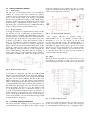
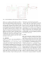
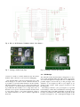
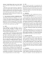
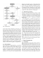
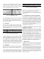
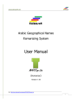
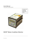
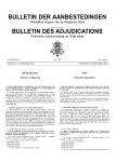
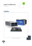
Multiple Technology Tag
For Seamless Localization
Roel Van Hoylandt, Bob Claerhout, Tim Denis, Charles Vercauteren, Maarten Weyn.
Abstract—The goal of this research is to design a battery powered electronic device that can be used in Real Time Locating Systems.
The device should be well equipped so it can be used for tracking persons and objects based on received signal strengths values
from Wi-Fi and GSM networks. GPS-based tracking is also made possible. Every smart-phone is equipped with hardware for these
requirements. The hardware on smart phones however, is not optimized for low energy consumption during continuous localization.
For this reason they’re not suited for long-term continuous use. This paper introduces a working hardware design and explains the
used program structure. In addition, the power consumption of the circuit is also explained. The multiple technology tag is designed
and programmed in function of low energy consumption, for a maximum up-time on a single battery-charge. A battery life time of more
than 61 days can be reached when only Wi-Fi is used, and when the location is updated every two minutes. Repeating a sequence of
updating the location ten times using only Wi-Fi, updating once using only GSM and updating once using GSM and GPS, can be done
for more than 18 days. This can only be maintained when a sleep time of two minutes is used after each location update.
Index Terms—Multiple Technology Tag, Wi-Fi, GPS, GPRS, GSM, Battery powered, RSSI, RTLS, Localization
F
1
I NTRODUCTION
At present, many objects in our environment are connected in some way to computer-based technology. In
the near future, it is likely that the need for computerintegration will rise to even higher levels. One of the
shortcomings in the total integration between environment, humans and computer-based technologies is the
localization of people and objects. Nowadays, there are
already a number of localization technologies (based on
GPS, Wi-Fi, GSM, UWB, etc.) [6] which perform well, but
they all have one problem: they only work when they
are used in a specific environment or application (e.g.
GPS only works when enough satellites are detected).
The goal of ”the Multiple Technology Tag” is to combine existing technologies and create a device that can
locate people and objects in any given environment.
The tag is designed to automatically switch to other
technologies when changing from one environment to
another. While moving indoors, it could be possible
that the tag switches from GPS localization to Wi-Fi
localization for tracking and from GPRS to Wi-Fi for
communication with the server. If the tag is unable to
receive a valid GPS-signal, the tag can make use of the
received signal strengths from GSM base stations. This
data can also be used to calculate the coarse position of
Roel Van Hoylandt, Charles Vercauteren and Maarten Weyn are with Artesis
University College Antwerp, dept. of Applied Engineering: Electronics-ICT,
Paardenmarkt 92, B-2000 Antwerpen, Belgium.
E-mail: [email protected], [email protected] and
[email protected]
Bob Claerhout and Tim Denis are with AtSharp, BVBA Kromstraat
64C/9B, 2520 Ranst, Belgium.
E-mail: see http://www.atsharp.com/
the tag [6].
In Section 2 the hardware design of the tag is explained. Section 3 discusses different ways to do localization and data transmissions. The software design is
explained in Section 4. Section 5 contains information
about the power consumption used by the different
modules and circuits. Some use cases and other possibilities with the same hardware are listed in Section 6. The
conclusion over the multi technology tag can be found
in Section 7.
2
H ARDWARE D ESIGN
An overview of the hardware can be seen in the block
diagram on Figure 1. The Wi-Fi module is used as main
controller, it is connected with the GPS and GSM module
via UART. It is also connected to multiple sensors (e.g.
motion sensor and push button). Three LEDs and some
Fig. 1. Hardware Block Diagram
control lines for the GPS and GSM module are connected
as normal GPIO. A Li-Po battery powers the GPS module
and the 3.3 voltage step down converter. The battery
voltage is measured by the Wi-Fi module via a sensor
input. The GSM and Wi-Fi module are powered via the
3.3 voltage step down convertor.
2.1
Battery and Battery Charger
2.1.1 Battery Type
The tag uses a rechargeable battery for powering the
circuits. To increase the time between two battery
recharges, power consumption is one of the major design
issues. Good design starts with finding components
which are energy efficient. A battery with a high energy
density is used so the physical dimensions can be small.
In this design a Lithium-Ion Polymer battery is used.
The battery has a nominal capacity of 1300 mAh and an
output voltage between 3.0 Volt and 4.2 Volt.
2.1.2 Battery Charger
To charge the battery, we implemented a charger in the
tag. Because we use a Lithium-Ion Polymer battery, a
specific charger is needed. The MCP73833 is an Integrated Circuit (IC) with an Lithium-Ion and Lithium-Ion
Polymer charger inside. This IC is a good choice because
it makes it possible to charge the battery by using 5
Volt (e.g. an USB-port). Another advantage of this IC
is that it needs a low number of external components.
Figure 2 shows the circuit arround the MCP73833. In the
prototype of the tag two LEDs are integrated. A green
LED lights up when the battery is fully charged, the
yellow LED lights up when the battery is charging. A
10 kΩ resistor (R3 ) is used to limit the charge current to
a maximum of 100 mA [1] . This value is chosen so that
from such a battery can be as high as 4.2 Volt. A voltage
regulator is implemented on the tag. Figure 3 shows the
circuit of this step down converter.
Fig. 3. 3.3 Volt Step Down Converter
The voltage reduction is realized using a
TPS62291DRV IC. It can handle currents with a
maximum of 1 A. JP1 (see Figure 3) can be used
for powering external circuits. The TPS62291DRV is a
DC/DC converter and switches at a fixed frequency of
2.25 MHz. At light load it enters a power save mode.
The device uses 15 µA when there is no output current.
With a battery voltage between 3.8 Volt and 4.2 Volt
an efficiency from 90 % or more can be reached for
currents higher than 0.6 mA [2].
2.3
GPS
When the device is placed in a location where no WiFi localization is possible, a GPS receiver can be used
when GPS signals can be received. The circuit from the
Fig. 2. Battery Charger Circuit
it is possible to charge the tag from any standard USB
2.0 port, some motherboards power down the USB port
if the current given by the port is to high. Default USB
2.0 ports can also deliver 500mA, but this needs some
digital negotiation. To use this feature extra hardware
needs to be implemented on the tag. Some batteries have
an integrated thermistor. By measuring the resistance of
this thermistor, the charger can lower the charge current
when the battery becomes too hot. The battery used
in our design doesn’t have a thermistor inside so R4
is used to mislead the battery-charger. A resistance of
10 kΩ represents a thermistor at 21◦ C. The battery can
not be overcharged, the MCP73833 has an end-of-charge
control circuit inside. Also an automatic recharge circuit
is implemented in the IC [1].
Fig. 4. A1035-H GPS Receiver
2.2
3.3 Voltage Step Down Converter
The Wi-Fi and GPS modules are not designed to be
powered directly by a LiPo-Battery. The output voltage
GPS receiver is show in Figure 4. The receiver is powered
by the 3.3 voltage step down converter. The prototype
of ”the Multiple Technology Tag” is equipped with a
Fig. 5. GL865 GSM Module, SIM-Card Holder and SiP32411 Load Switch
header (JP3 , see Figure 4) which makes it possible to
measure the current used by the GPS-receiver. For normal use this header should be shorted electrically. The
receiver is connected to a backup-voltage which keeps
the internal RTC running this decreases the Time To First
Fix (TTFF) after a power-on event. A diode is used to
power the backup-circuit of the GPS-receiver because it
is also possible to use an ultracap in combination with
the A1035-H in applications where no battery is used.
This diode protects the charge-circuit inside the GPSModule. For communication with the Wi-Fi-module, two
UART lines are used (Tx and Rx ). The header JP4 (see
Figure 4) can be used to connect a logic analyzer during
debugging. The GPS-module is switched off when it is
not used. This is done by the Wi-Fi module, it emits
a short positive pulse on the line connected to pin 17
from the GPS module. Sending another pulse switches
the module to the on state.
2.4
GSM/GPRS
In Figure 5 the circuit of the GL865 GSM-Module is
shown. It also contains a SIM-Card Holder and a Load
Switch (SiP32411).
There are two types of the GL865 module available
on the market, the GL865-DUAL and GL865-QUAD. The
GL865-DUAL can be used in countries where operators
use the 900 MHz and 1800 MHz frequency bands. These
are the frequencies used in Europe. The GL865-QUAD
can also be used with the 850 MHz and 1900 MHz
frequencies but uses a little more power.
If the GL865 is in idle-mode it is possible to disconnect
it’s power-supply on pin 38. This is not necessary but
it will lower the battery-consumption with a current of
approx. 630µA [3]. The load switch makes it possible
to disconnect and re-connect the power to the GSMmodule by switching a simple enable-signal [4]. This
enable-signal is controlled by the Wi-Fi-module.
Like the GPS-receiver, the GSM-module also needs
a backup voltage. This voltage makes it possible to
get a faster connection with the GSM network after a
power-on event. JP6 (see Figure 5) is a test-header to
measure the current used by the GSM-module. A logic
analyser can be placed on header JP5 (see Figure 5) for
easy debugging. JP5 is placed on the two UART lines
which are used to create a connection between the GSMmodule and Wi-Fi-module. The GSM-module accepts
voltages as high as 2.8 Volt on the receiving UART pin.
A voltage divider (R6 and R7 in Figure 5) is used to
reduce the higher voltage (3.3 Volt) that is placed by the
Wi-Fi-module on the Tx line.
2.5
Wi-Fi
Figure 6 shows the circuit of the RN-171 Wi-Fi-module.
This module is designed for applications where energy
consumption is a critical issue. A tilt/motion switch is
used to detect movement of the tag. The state of this
switch is checked using the current loop sensor inside
the Wi-Fi-module [5]. Three LEDs are used for debugging and signalizing, a logic analyzer can be connected
to JP8 (see Figure 6). A standard push-button is also
integrated on the board. R13 is a pull-up resistor, C17
is used for de-bouncing, R14 is responsible for recharge
the debounce-capacitor once the push-button is opened
again. JP7 (see Figure 6) is used to measure the current used by the Wi-Fi-module. For communication
with the GSM-receiver and GPS-module, two UART
communication lines are used. Other lines are used to
check the power-state from the GSM-module, control the
load switch, and change the power-state from the GPSmodule. For measuring the battery voltage, a voltage
divider (R8 and R9 ) is used because the sensor-inputs
can only measure voltages up to 400 mV. A 16-pins ISP-
Fig. 6. RN-171 Wi-Fi Module, Tilt/Motion Switch, Push-Button,...
Fig. 7. Prototype PCB-Design (Top)
Fig. 8. Prototype PCB-Design (Bottom)
2.6
connector is used to load the firmware into the Wi-Fimodule. This connector is also used for debugging.
The Wi-Fi-module is the most important part of the
whole design, it is used as main controller because it
is possible to load self-written firmware in the module.
The Wi-Fi module is able to go in a sleep state and it can
wake up due to an internal timer interrupt. This makes
it possible that the module is in a sleep state most of
the time to save power. The Wi-Fi module decides when
to scan Wi-Fi, when to use GPS localization, when to
use GSM localization, etc. This is further explained in
Section 4.
PCB Design
The Printed Circuit Board (PCB) is designed as a twolayer PCB. Standard 0805 and 1206 sized components
are used. Through hole components are avoided where
possible. Figure 7 shows the top of the prototype. The
antennas A1 (see Figure 4) and A2 (see Figure 6) are
placed in the corners, with a proper clearance to the
ground plane.
The battery-connector (JP2 ) (see Figure 7) is placed
horizontally to reduce the total thickness of the tag with
plugged in cables. The SIM-card holder is placed on top
for easy accessibility. The GSM-module is placed at the
bottom (see Figure 8). On a subsequent design of the
PCB, it is recommended to make use of an micro-SIMcard and a smaller GSM-module. Placing more components at the bottom of the PCB also reduces the size of
the tag.
The whole circuit, PCB and software is designed to
work with varying set-ups. If GPS and GSM are not
needed, a cheaper tag can be realized, just by not soldering them on the board. The software detects the absence
of these modules and only uses Wi-Fi for localization
and communication. Even if the modules, for whatever
reason, get broken during normal use, the software will
detect this and switch to an alternative localization and
data transmission method.
3
L OCALIZATION
AND DATA COMMUNICATION
The multiple technology tag is designed to work in cooperation with an RTLS server. The RTLS server is used
to calculate the position from the tag when Wi-Fi or GSM
is used, so no complex localization algorithms need to
be implemented on the tag. The communication with the
RTLS server is done by sending TCP or UDP packets
from the tag to the server. The packages are formatted
as described in the locON protocol. The RTLS server is
also used to read out the location of the tag.
3.1
Wi-Fi
Inside buildings it is usually impossible to receive a
proper GPS-signal. This means GPS can’t be used for
localization inside a building. A technique used for
indoor tracking and localization is to make use of the
already installed Wi-Fi access points. Two types of WiFi-based localization principles are used.
One principle, called infrastructure based tracking,
uses the access points for measuring the RSS from the
sending mobile devices. A drawback to this system is
the need for communication with the access points. The
Real Time Locating System (RTLS) server needs to be
connected to the access points to receive the measured
data, thus existing infrastructure need to be adapted.
Also, not every type of access point available to the
market is capable of doing RSS measurements. While the
tag is not designed to use this method, the localization
of the tag will not be a problem in places where this
system is used. This is due to the fact that infrastructurebased technologies can localize every device in range,
that periodically sends a Wi-Fi packet.
Using the second method, the mobile device does
the RSS measurement of the receiving access points.
This system can be used in every environment, even
in areas where no connection to the access points can
be made. Once the mobile device has scanned all the
access points in range, it connects with one of them. Once
authenticated, the mobile device sends the collected data
to the RTLS server using the existing connection. [6]. If
no connection can be made to one of the access points,
the RSS data can be send over a GPRS connections, this
is not yet implemented into the software design.
3.2
GPS
When localization using Wi-Fi is not possible due the
lack of access points in range, or authentication is not
possible, other localization techniques can be used. If
GPS signals can be received, the GPS receiver can be
used to locate the device. Once the GPS receiver has
calculated the position of the tag, this data needs to
be sent to the RTLS server. This can be done using the
GSM/GPRS module.
3.3
GSM/GPRS
If Wi-Fi localization or data communication is not possible, localization and data transmission can be done by
using the GSM/GPRS module.
For localization by GSM network, the same principle
of Wi-Fi localization is used, the module measures the
signal strengths of the receiving base stations. However
there is small difference, where Wi-Fi scans all 13 channels in 2.6 seconds with a default scan time of 200 ms for
each channel, scanning of all receiving base stations can
take as much as two minutes. To solve this problem only
the neighbouring base stations are scanned. The GSM
module receives a message of the serving cell which
informs the module about the channel numbers that are
used by the neighbouring cells. The module can finish
the cell-scan relatively quick, knowing which channels
to scan. The drawback is that the scan is limited to
a maximum of seven base stations from the serving
provider.
The GSM/GPRS module can also be used for data
communication with the RTLS server. The module only
supports GPRS, other data transmission techniques like
EDGE, UMTS and HSDPA are not supported. Because
the data-packets that need to be send are really small,
high transmission speed protocols are not necessary.
4
SOFTWARE DESIGN
The firmware, which is loaded into the Wi-Fi module
contains an embedded operating system (called eCos)
and is compiled for the use on a 32-bit G2C547 chip.
The firmware has an application loader which loads
self-written applications. The applications are written in
C and compiled with the Bare-C Cross-compiler (BCC)
[7]. The software application, is split in three major
parts. This is done for better energy efficiency, because
loading a big program uses more power then loading
a small program. The software is designed to minimize
the number of reload events. Figure 9 shows the program
structure.
4.1
Initialization
One program is called ”MTT-Init”, which is the default
start-up program. If the battery of the module gets connected, ”MTT-Init” gets loaded. The module receives an
power on reset event, this event starts a function which
initializes the hardware. The three LEDs blink at an
RTLS server, the module creates a locON packet with all
the RSS values and mac-addresses of all the Wi-Fi access
point in range. Also temperature and battery measurements are included into the packet. The following step
is sending the packet to the RTLS-server of the existing
Wi-Fi connection. Once this is done the module goes to
a sleep mode. After a timer interrupt the module wakes
up again and ”MTT-send-WiFi” is loaded again.
4.3
Fig. 9. Program Flow
specific pattern which is dependent on the battery voltage, the software checks if the GSM and GPS modules
are present and working. The motion sensor also gets
initialized. Next, the software tries to associate with an
access point. During configuration time, three network
names, authentication techniques and passwords can be
programmed into the tag, the tag only tries to associate
with one of these three access points. If association was
possible, it loads the ”MTT-Send-WiFi” software. If no
association can be established, the software tries it again
for a configurable number of times. Because a short scantime is used to save energy, not every wireless network
available is always found by the module, this is the
reason why the rescan possibility is included. If the
maximum number of rescans is reached the software
loads the ”MTT-Send-Gsm” software, the maximum of
number of rescans can be changed in a configuration file.
4.2
Wi-Fi localization
The second program, ”MTT-Send-WiFi”, is used when
Wi-Fi networks are available and association was possible. If no connection can be made with the access
point, the software tries it again for a specific number
of times. if the maximum number of rescans (which is
defined in a configuration file) is reached, the module
switches to GPS and/or GSM localization and GSM data
transmission. If a connection can be established with the
GSM and GPS localization
If Wi-Fi is not available, the module switches to GSM
and GPS localization. First the program checks if the
GPS-module is present, if it is not, the program does
a cell monitor. The RSS values and information needed
to identify the base stations are put in a locON package
together with the results of a temperature and battery
measurement.
If the GPS-module is available, the program powers it by sending a positive puls on the gps-power-on
line. Once the GPS-module is powered on, it sends an
NMEA (National Marine Electronics Association) code
every second [8]. The GPS-module is configured to only
send GGA-messages, this message contains information
such as longitude, latitude, MSL-altitude, UTC-time, etc.
Because the GSM-module is connected to normal GPIOpins, the hardware UART buffer from the Wi-Fi module
can’t be used, to solve this problem, software routines are
used. The Wi-Fi module goes to sleep state once an GGAmessage without valid position data is received. After
a timer interrupt the device wakes up to receive and
decode the next GGA-message. The sleep-time can be
configured. The maximum number of wake-ups before
switching off the GPS-module can also be set.
Once the GPS-module sends a GGA-message containing a valid position, the Wi-Fi modules places this data
into a locON packet and sends it to the RTLS-server
using a GPRS-connection. If no GGA-message with valid
position data can be received after a number of wakeups, the GSM-modules wakes up and a cell-monitor is
done.
For communication between the GSM-module and WiFi-module, AT-commands are used.
5
5.1
P OWER C ONSUMPTION
Wi-Fi Module
Table 5.1 shows the average Wi-Fi module currents in
different situations, the typical times are given too. To
define the typical times, the average time of five tests
is calculated. If the tag is used with only the Wi-Fi
module soldered on the PCB, a theoretical stand-by time
of over five years can be achieved, this is because the
voltage regulator and battery voltage divider also uses
some current. In reality such a long stand-by time is
impossible, because of the self-discharge of the battery.
The last row in the tables shows the values when no GPS
fix is found after 10 wake-ups with 1800 ms in between.
When the GPS and GSM module are not in use, while
doing a scan every two minutes, a battery life time of
more than 61 days is possible. If the tag is used only
during working days, and charges in the weekend, the
location can be updated every seven seconds.
Situation
Sleeping
MTT-Init (Power On)
MTT-Init
MTT-Send-WiFi
MTT-Send-GSM(GSM only)
MTT-Send-GSM (GSM + GPS)
Average Current
3.50 µA
27.817 mA
31.968 mA
32.334 mA
14.194 mA
6.299 mA
Typical Time
3.62 s
2.75 s
3.20 s
32.00 s
58.10 s
TABLE 1
Power Consumption Wi-Fi Module
For example, while using Wi-Fi on a Nokia N97 mobile
device and updating every 30 seconds, a battery life
time of 40 hours can be reached [9]. Scanning every 30
seconds with the multiple technology tag is possible for
periods up to 412 hours.
5.2
GPS Module
Table 5.2 shows the current used by the GPS module.
A small current is needed to run the internal real time
clock, this allows the module to decrease the time to the
first fix. During acquisition the Wi-Fi module is powered
off most of the time.
Situation
Sleeping
Acquisition
Average Current
6.36 µA
24.677 mA
Typical Time
(Maximum time is configurable)
TABLE 2
Power Consumption GPS Module
For better TTFF, the software can be extended with code
which sends Extended Ephemeris (EE) data to the GPS
module. Transfering the 7 day EE data, which has a
size of approximately 70 kilobytes of data, from the
Wi-Fi module to the GPS module takes a minimum
of 30 seconds when using higher baudrates and SiRF
commands, instead of NMEA commands. The EE data
can be downloaded from the GPS module manufacturers
server. This feature is not yet include in the software.
5.3
GSM Module
Table 5.3 shows the current used by the GSM module,
when the load switch is opened, no current can flow
trough it, only a very small current is leaking trough.
The second line in the tables shows the average current
which is taken while starting up the module, registering
to the cellular network, doing a cell monitor, opening a
socket to the RTLS server, sending a locON packet to the
Situation
Off (Load Switch open)
Cell monitor and Packet send
Average Current
50 nA
42.420 mA
Typical Time
29.4 s
TABLE 3
Power Consumption GSM Module
RTLS server, closing the socket, disconnecting from the
cellular network and switching of the module.
The GSM module also uses a backup voltage for
powering internal circuits. The current running here is
rated at 2 µA.
5.4
Voltage Regulator and Battery Voltage Divider
If every module is powered off, the battery drain is at
minimum. The voltage regulator still uses a current of
15 µA, the voltage regulator can be disabled by pulling
the enable line low [2]. In this design this is not done,
because the voltage regulator is used to feed the backup
circuits and Wi-Fi and GPS modules during sleep. The
current flowing trough the voltage divider is as high as
8 µA when the battery is fully charged. The load switch
uses less then 1 µA when it is not in use.
This results, for a tag with all modules soldered on, to
a minimum current of 35,91 µA.
6
OTHER POSSIBILITIES
HARDWARE , USE CASES
WITH
THE
SAME
The multiple technology tag can be used for many
applications. For example, it can be used to track forklifts
while they are driving from inside the storage building
to the loading docks outside, also the pallets can be
tracked from manufacturer to the final warehouse.
Another possibility with the same hardware is to
build an ultimate fingerprinting device for real time
localization systems which can scan Wi-Fi and cellular
base stations while using GPS for exact localization. If
the tag is given to people that pass every street in the city,
like personnel of the postal service, it should be possible
to fingerprint a whole city in a couple of days. This
requires some changes in the existing software, because
it currently isn’t designed for such an application.
7
C ONCLUSION
The design of the multiple technology tag as presented
in this paper can be used in real-world applications.
Although some minor changes can still be made to
increase the battery life.
When a sleep state of 120 seconds is used after every
location update, a battery life time of more than 18 days
can be reached while running the following cycle: update
the location 10 times while using only the Wi-Fi module,
update the location once using only the GSM-module
and send the GPS coordinates over GPRS once. The last
example assumes that the GPS module finds a fix in
under two seconds.
The software can be adapted for many situations and
it is possible to use no GPS or GSM module. Some
adaptable timers and counters are build into the software
so the software can be optimized for several specific situations. When placing the tag into a car, Wi-Fi localization
is not really important, but for localizing people inside
a building, Wi-Fi is the preferred localization technique
and GPS is not useful. GSM localization can also be
used in the last scenario. All these choices can be made
during the configuration of the software, which makes
the multiple technology tag a strong tool for real time
locating systems.
R EFERENCES
[1] Microchip, “MCP73833/4 - Stand-Alone Linear Li-Ion / LiPolymer Charge Management Controller,” p. 32, 2009.
[2] T. Instruments, “1-A Step Down Converter in 2 x 2 SON Package,”
p. 24, 2008.
[3] Telit, “GL865 Hardware User Guide,” p. 71, 2011.
[4] V. Siliconix, “2 A, 1.2V, Slew Rate Controlled Load Switch,” p. 13,
2011.
[5] R. Networks, “WiFly GSX 802.11 b/g Wireless LAN Module,” p. 18,
2012.
[6] M. Weyn, “Opportunistic seamless localization,” p. 162, 2011.
[7] G. Mircosystems, “G2C547 Programmer’s Reference Manual,” p.
111, 2008.
[8] Maestro, “GPS Receiver A1035-H - User’s Manual,” p. 38, 2009.
[9] I. Constandache, S. Gaonkar, M. Sayler, R. Choudhury, and L. Cox,
“Enloc: Energy-efficient localization for mobile phones,” in INFOCOM 2009, IEEE. IEEE, 2009, pp. 2716–2720.