1
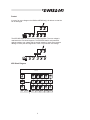
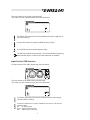
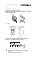
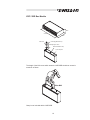
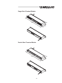
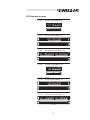
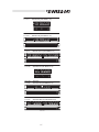
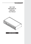
XSP / XSR
DMX Splitter &
RDM Hub
User Manual
XSP / XSR
DMX Splitter /RDM Hub
User Manual
Issue 4 (2010-06-15)
Copyright © 2010 SWISSON AG
No part of this documentation may be reproduced or transmitted in any form or by
any means, electronic or mechanical, including photocopying and recording,
without the prior written permission of SWISSON AG.
The information in this documentation is supplied without warranty of any kind,
either directly or indirectly, and is subject to change without prior written notice.
SWISSON its employees or appointed representatives will not be held
responsible for any damages to software, hardware, or data, arising as a direct or
indirect result of the product(s) mentioned herein.
Dieses Dokument darf weder vollständig noch auszugsweise in irgendwelcher
Form reproduziert, kopiert oder gespeichert werden, ohne das vorherige
schriftliche Einverständnis der Firma SWISSON AG.
Die Informationen in diesem Dokument sind ohne jegliche Gewähr und können
ohne vorherige Ankündigung jederzeit im Sinne des technischen Fortschritts
geändert werden. SWISSON und seine Angestellten oder seine Vertreter sind
nicht verantwortlich für Schäden, welche direkt oder indirekt mit den in diesem
Dokument beschriebenen Geräten entstanden sind.
Issued by
SWISSON AG
Fabrikstrasse 21
CH-3250 Lyss
Switzerland
E-Mail: [email protected]
SWISSON of AMERICA Corp.
2419 East Harbor Blvd. #34
Ventura, CA 93001
U.S.A.
XSR and XSP
DMX Splitter/Booster &
RDM Hub
Introduction
The XSR and XSP series of RDM hubs and DMX splitter/boosters, from
SWISSON can be easily and economically integrated into any lighting system
where you wish to spilt and boost DMX and RDM signals.
While the XSP spiltts and boost only DMX signals, the XSR also detect RDM
Data and use its bidirectional functionality to report back to the Controller
(Lighting Board).
All output ports on both XSP and XSR are optically isolated. A strong power
supply allows a reliable operation in a wide voltage range. A large program of
XSR and XSP devices is available; consisting of different housings, different
connector types and different numbers of input and output ports.
Applications
!
!
!
!
Concert Lighting
Live Events
Multimedia Shows
Theater
! TV Sets
! Theme Parks
! Achitectural Lighting
Typical Application
DMX Light Board
with or without
RDM functionality
DMX Fixtures
with or without
RDM functionality
DMX Dimmers
with or without
RDM functionality
The XSR works within DMX / RDM environments and works as well as in pure DMX
environments. The XSR is a good solution for those who expect to use RDM in future
because the XSR acts as a normal DMX splitter if there is no RDM Data.
The XSP work only within DMX evironments.
2
Benefits using a XSP/XSR Splitter / Booster
Boost
On installations with excessively long cable runs the DMX and/or RDM signal can
be compromised or significantly weakened by the distance.
Good signal
Weak signal
bad signal
The XSP/XSR boosts the signals thus eliminating signal interference
Good signal
Weak signal
Good signal
Regenerate
In harsh environments DMX and RDM signals can be disturbed or corrupted.
Good signal
Disturbed
signal
disturbance
bad signal
disturbance
The XSP/XSR cleans and regenerates the signals.
Good signal
Disturbed
signal
Good signal
disturbance
3
Split
A simple split of signal lines is not allowed. The bidirectional operation of RDM is
even more sensitive to the split on that than DMX.
not allowed
A split of the signal lines is possible with the XSR / XSP by using different output
ports
Reduces reflection problems
Signal reflection is a common problem on large DMX installations or on long
signal lines. The bidirectional operation of RDM is more sensitive to reflections
than DMX.
Weak
reflection
with large
delay.
Signal OK
Strong
reflection
with large
delay.
Bad signal !
Strong
reflection
with small
delay.
Signal OK
The XSP/XSR split the line into smaller segments with a regenerated signal,
which reduces the delay of the reflection on each segment.
Reflection
with small
delay.
Signal OK
Reflection
with small
delay.
Signal OK
4
Protect
In case of an over voltage on the DMX and RDM line(s), all devices on that line
can be damaged.
The XSP/XSR separate the line into multiple segments. The over voltage is
restricted to the concerned segment. The XSP/XSR itself is well protected
against transient over voltage and the optical isolation of each port prevents a
damage of other ports and segments in case of a permanent over voltage.
XSP Block Diagram
Control Logic
Optical
Isolation
Optical
Isolation
Optical
Isolation
Optical
Isolation
Optical
Isolation
Line
Termination
Transmitter
Transmitter
Transmitter
Transmitter
Transmitter
Protection
Protection
Protection
Protection
Protection
Protection
Out Port 1
Out Port 2
Out Port 3
Out Port 4
Out Port 5
In Port
Thru Port
Termination
Receiver
5
XSR Block Diagram
Control Logic
Optical
Isolation
Optical
Isolation
Optical
Isolation
Optical
Isolation
Optical
Isolation
Line
Termination
Tranceiver
Tranceiver
Tranceiver
Tranceiver
Tranceiver
Protection
Protection
Protection
Protection
Protection
Protection
Out Port 1
Out Port 2
Out Port 3
Out Port 4
Out Port 5
In Port
Thru Port
Termination
DMX Only
Teanceiver
Mains Connection
Two different Mains connections are available:
The US versions are delivered by Swisson with a "Edison Plug" (NEMA-5-15).
These models has a "-US" suffix at the end
The International versions are delivered without any plug.
Swisson distributors or dealers may deliver the devices with a country specific
plug.
Yellow/Green : Earth
Brown : Phase
US Versions (-US suffix)
Blue : Neutral
International Versions
Input Section XSP Versions
The Input section of the versions with XLR connectors
6
The Input section of the versions with terminals:
The “input” and “thru” terminals are at the rear of the device.
The Power LED shows if the device powered and if power supply unit of
the XSP is working
A green LED shows if a signal is available at the Input port.
A red LED shows if the received signal is faulty
The XSP has a built in line termination. This can be activatet by pressing
the termination button. A LED shows if the termination is activated.
Input Section XSR Versions
The Input section of the XSR versions with XLR connectors
The Input section of the XSR versions with terminals:
The “input” and “thru” terminals are at the rear of the device.
The Power LED shows if the device powered and if the power supply
unit of the XSR is working
A multicolor LED shows if a signal is available at the Input port. The LED has
3 different states:
Off:
No signal present
Green: Signal is present and Ok
Red: Signal is present but faulty
7
The RDM LED show if RDM data packets are preset. In a pure DMX
environment this LED remains off.
The XSR has a built in line termination. This can be activatet by
pressing the termination button. A LED shows if the termination is
activated.
The "dmx only" function of the XSR allows removal off all RDM data
from the outupt ports. A LED shows if the "dmx only" function is
activated.
Input and Thru Port
The THRU port is hardwired with the INPUT port and allows to daisy-chain the
devices even when the XSR is not powered. On all XSP and XSR models with 5Pin XLR connector the pin 4 and 5 are also looped thru to the THRU port. On all
other models pin 4 & 5 are not available.
Protection
Line
Termination
Input Port
Teanceiver
Thru Port
1
2
3
4
5
1
2
3
4
5
Line Termination
All XSP and XSR splitters have a built-in line termination. The termination is
activated by pressing the termination button. On terminal and Installation version
the button is only accessible with a tool (such as a paper clip).
8
DMX Only (only on XSR models)
The "DMX only" function removes all non DMX data before forwarding the data to
the output ports. RDM data will be removed too.
This can be helpfull when DMX devices are not compatible and do not check the
data they receive as valid DMX.
The "DMX only" function is activated by pressing the "DMX only" button. On
terminal and Installation version the button is only accessible with a tool.
Output Ports
The output section of
the versions with XLR
connectors:
The OUTPUT section
of the versions with
terminals:
The OUTPUT
terminals are at the
rear of the devices.
Each output port is individually optically isolated, meaning that it is totally
isolated from the other output ports and the input selection.
The Pins 4&5 on the models with 5-Pin XLR connectors are not connected.
Controller Supply
Port Supply
Output Port
Control
Logic
Optical
Isolation
Tranceiver
Bias
Network
Protection
n.c.
1
2
3
4
5
On the XSR the signal LED of the OUTPUT ports show if a valid signal is
transmitted. It works bidirectionally:
When sending DMX or RDM packets and when receiveing RDM
responces.
This LED is not available on the XSP models.
9
XSP / XSR Box Models
45mm
217.5mm
112mm
Mains cable
Mains plug (US-Versions only)
cable length approx. 145cm
M10 female threat for clamp
Eye for savety wire
The length of the M10 screw which enters the XSP/XSR should not exceed a
maximum of 20mm.
20mm MAX
Clamp is not included with the XSP/XSR.
10
Single Rack Models
482mm
45mm
112mm
cable length approx. 145cm
Mains plug (US-Versions only)
Double Rack Models
482mm
45mm
112mm
cable length approx. 145cm
Mains plug (US-Versions only)
11
Single Rack Terminal Models
482mm
45mm
112mm
Double Rack Terminal Models
482mm
45mm
112mm
12
Terminal Models
The terminal models of the XSP/XSR comes with plugable treminal blocks. The
terminal blocks are located at the rear of the device.
XSP/XSR terminal models are shipped with the terminal blocks. They can accept
wires up to AWG 17 (~1mm2)
Installation model
The XSP/XSR installation modell is made to be installed by certified
professionals. This version has no plugs. All connections are located inside of the
device.
input port
mains
thru port
output ports
cover
grommets
13
XSP standard program
10 11 63
11 11 63
XSP-3B
XSP-3B-US (with NEMA 5-15)
Front view
Rear view
10 11 74
11 11 74
XSP-3R
XSP-3R-US (with NEMA 5-15)
Front view
Rear view
10 11 85
11 11 85
XSP-3R-3R
XSP-3R-3R-US (with NEMA 5-15)
Front view
Rear view
10 11 62
11 11 62
XSP-5B
XSP-5B-US (with NEMA 5-15)
Front view
Rear view
10 11 72
11 11 72
XSP-5R
XSP-5R-US (with NEMA 5-15)
Front view
Rear view
10 11 82
11 11 82
XSP-5R-5R
XSP-5R-5R-US (with NEMA 5-15)
Front view
Rear view
14
10 11 60
11 11 60
XSP-5B5
XSP-5B5-US (with NEMA 5-15)
Front view
Rear view
10 11 70
11 11 70
XSP-5R5
XSP-5R5-US (with NEMA 5-15)
Front view
Rear view
10 11 80
11 11 80
XSP-5R5-5R5
XSP-5R5-5R5-US (with NEMA 5-15)
Front view
Rear view
10 11 87
11 11 87
XSP-5R2-5R2
XSP-5R2-5R2-US (with NEMA 5-15)
Front view
Rear view
10 11 84
11 11 84
XSP-5R-5R5
XSP-5R-5R5-US (with NEMA 5-15)
Front view
Rear view
10 11 86
11 11 86
XSP-5R-3R
XSP-5R-3R-US (with NEMA 5-15)
Front view
Rear view
15
10 11 50
11 11 50
XSP-TR5
XSP-TR5-US (with NEMA 5-15)
Front view
OUT 5
OUT 4
OUT 3
OUT 2
OUT 1
THRU
IN
Rear view
10 11 51
11 11 51
XSP-TR5-TR5
XSP-TR5-TR5-US (with NEMA 5-15)
Front view
OUT 5
OUT 4
OUT 3
OUT 2
OUT 1
THRU
IN
OUT 5
OUT 4
OUT 3
OUT 2
OUT 1
THRU
IN
Rear view
10 11 98
XSP-IB5-W
Front view
Rear view
XSR standard program
10 12 10
11 12 10
XSR-3B
XSR-3B-US (with NEMA 5-15)
Front view
Rear view
10 12 20
11 12 20
XSR-3R
XSR-3R-US (with NEMA 5-15)
Front view
Rear view
10 12 30
11 12 30
XSR-3R-3R
XSR-3R-3R-US (with NEMA 5-15)
Front view
Rear view
16
10 12 11
11 12 11
XSR-5B
XSR-5B-US (with NEMA 5-15)
Front view
Rear view
10 12 21
11 12 21
XSR-5R
XSR-5R-US (with NEMA 5-15)
Front view
Rear view
10 12 31
11 12 31
XSR-5R-5R
XSR-5R-5R-US (with NEMA 5-15)
Front view
Rear view
10 12 16
11 12 16
XSR-5B5
XSR-5B5-US (with NEMA 5-15)
Front view
Rear view
10 12 26
11 12 26
XSR-5R5
XSR-5R5-US (with NEMA 5-15)
Front view
Rear view
10 12 33
11 12 33
XSR-5R5-5R5
XSR-5R5-5R5-US (with NEMA 5-15)
Front view
Rear view
17
10 12 35
11 12 35
XSR-5R2-5R2
XSR-5R2-5R2-US (with NEMA 5-15)
Front view
Rear view
10 12 34
11 12 34
XSR-5R-5R5
XSR-5R-5R5-US (with NEMA 5-15)
Front view
Rear view
10 12 32
11 12 32
XSR-5R-3R
XSR-5R-3R-US (with NEMA 5-15)
Front view
Rear view
10 12 50
11 12 50
XSR-TR5
XSR-TR5-US (with NEMA 5-15)
Front view
OUT 5
OUT 4
OUT 3
OUT 2
OUT 1
THRU
IN
Rear view
10 12 51
11 12 51
XSR-TR5-TR5
XSR-TR5-TR5-US (with NEMA 5-15)
Front view
OUT 5
OUT 4
OUT 3
OUT 2
OUT 1
THRU
IN
OUT 5
OUT 4
Rear view
10 12 51
XSR-IB5-W
Front view
Rear view
18
OUT 3
OUT 2
OUT 1
THRU
IN
Technical Data
Mains Voltage
110 / 230 [VAC]
Main Frequency
50/60 [Hz]
Current Consuption
Single Units
0.25 [A]
Current Consuption
Double Units
0.5 [A]
Operating Temperature
0F to 130F (-17!C to 55!C)
Protocol Standard
ANSI E1.11 (DMX-512)
ANSI E1.20 (RDM)
Safety Standards
EN60950-1
UL?????
EMC emmision
EN50081-1
EN50081-2
EMC immunity
EN50081-1
EN50081-2
Safety notes
Consider the following notes absolutely when you set up, connect and use the
XSP / XSR
!
Connect the cables only with the proper plugs and sockets.
!
Set the cables in an accident-proof fashion. Connected cables mustn't be
stressed mechanically too much.
!
Keep the device away from sources of electrical interference..
!
Only connect accessories certified for use with this device.
!
Never open the device yourself. Don't touch the plug contacts with metal or
sharp/pointed objects.
!
Clean the XSP/XSR DMX Splitter only with a soft, damp cloth. Don't use
chemicals or scrubbing means.
!
Protect the device against against exposure to: excessive humidity, liquids,
moisture, dust, direct sunlight.
!
Do not use the device in areas where it is exposed to direct sunlight.
!
Do not use the device in areas that are considered to be 'highly combustible'.
19
20