1
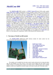
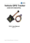
FL-10 User Manual (Economic/Basic AVL Terminal) Ver:1.1 Revised History Date 2012-05-12 2012-08-07 Version 1.0 1.1 Changes N/A - Revised One Press short call button and SOS button wire color; - Revised Speed Alarm buzzer to be GND output Copyright © 2011 Shenzhen C2S Technology Co., Ltd. All rights reserved. Editor Maggie Maggie Contents Index 1 INTRODUCTION ............................................................................................................................................. 4 1.1Attention .................................................................................................................................................... 4 1.2 Instructions of safety ............................................................................................................................ 4 1.3 About document ................................................................................................................................... 5 2 BASIC DESCRIPTION ..................................................................................................................................... 5 2.1 Package contents .................................................................................................................................. 5 2.2 Additional accessories ......................................................................................................................... 6 2.3 Basic Characteristics ....................................................................................................................... 6 2.3.1 GSM / GPRS features: .................................................................................................................. 6 2.3.2 GPS features: ................................................................................................................................... 6 2.3.3Hardware features: ......................................................................................................................... 6 2.3.4 Interface features: ......................................................................................................................... 6 2.3.5 Special features: ............................................................................................................................. 6 2.4 Mechanical features ............................................................................................................................. 7 3 CONNECTION, PINOUT, ACCESSORIES ................................................................................................ 8 3.1 LED status ................................................................................................................................................. 8 3.1.1 GPS LED indicator: ........................................................................................................................ 8 3.1.2 Status Work LED ............................................................................................................................ 8 3.2 Standard Socket 2x6 Power and I/O cable .................................................................................. 9 3.3 Insert SIMCARD ...................................................................................................................................... 9 3.4 Internal battery switch ....................................................................................................................... 10 3.5 Mini USB Usage.................................................................................................................................... 10 3.6 Wire connection and Accessories ................................................................................................. 13 4 FIRMWARE...................................................................................................................................................... 13 5 OPERATIONAL BASICS............................................................................................................................... 14 5.1 Operational Principals ....................................................................................................................... 14 5.2 Sleep mode ............................................................................................................................................ 14 5.3 Movement Sensor ............................................................................................................................... 15 5.4 Virtual Odometer................................................................................................................................. 15 5.5 Voice Functionality.............................................................................................................................. 15 5.6 Speed Limit Over and Buzzer Alert:.............................................................................................. 16 5.7 Driver working time Limit: ................................................................................................................ 16 5.8 GEO Fencing: ......................................................................................................................................... 16 5.9 Alarm working principals .................................................................................................................. 17 6 CONFIGURATIONS ...................................................................................................................................... 18 6.1 Configurator Software ....................................................................................................................... 18 6.1.1 Operation Menus: ................................................................................................................ 19 6.1.2 GPRS Parameters:........................................................................................................................ 20 6.1.3 Authorization Setting ................................................................................................................ 21 6.1.4 Device Status: ........................................................................................................................ 22 6.1.5 System Setting: ............................................................................................................................ 22 6.1.6 Other Setting: ............................................................................................................................... 25 6.2 Configuration by GPRS Commands: ............................................................................................ 27 7. SMS Command List .................................................................................................................................... 27 7.1 Configuration SMS commands: ..................................................................................................... 28 7.1.1 Setup Server SMS modem NO.:............................................................................................. 28 7.1.2 Setup authorized A/B/C Users: .............................................................................................. 29 7.1.3 Setup Call Center D Serve NO.:.............................................................................................. 29 7.1.6 Setup Speed over Limit value:................................................................................................ 30 7.1.7 Setup SMS Report Data time:................................................................................................. 31 7.1.8 Setup GPRS parameters:........................................................................................................... 31 7.1.9 Setup Time-based Data report Interval: (GPRS) .............................................................. 32 Copyright © 2011 Shenzhen C2S Technology Co., Ltd. All rights reserved. 7.1.10 Switch Off Time-based data report: .................................................................................. 32 7.1.11 Switch ON/OFF GPRS Data report when ACC Off ....................................................... 32 7.1.12 Setup Voice listen-in Call Back telNo................................................................................ 32 7.1.13 Setup Distance Report Parameter: ..................................................................................... 33 7.1.14 Setup Angle-based Report Angle Parameter ................................................................ 33 7.1.16 Activate SMS working mode: ............................................................................................... 34 7.1.17 Activate SMS+GPRS Working mode: ................................................................................ 34 7.2 Control function SMS Commands ................................................................................................ 34 7.2.1 Enable EngineImmobilizer ....................................................................................................... 34 7.2.2 Disabled Engine Immobilizer .................................................................................................. 34 7.2.3 Remote reboot Device .............................................................................................................. 35 7.3 Query functionSMS commands: .................................................................................................... 35 7.3.1 Query all authorized Phone Numbers ................................................................................ 35 7.3.2 Query current Speed over limit value ................................................................................. 36 7.3.3 Query current SMS Data Time setting ................................................................................ 36 7.3.4 Query current GPRS Parameter in memory ...................................................................... 36 7.3.5 Query device IMEI NO. .............................................................................................................. 36 7.3.6 Query vehicle Current status .................................................................................................. 37 7.3.6 Query GPS data by SMS with GPRMC format .................................................................. 37 7.3.7 Query GPS data by SMS with degree formats ................................................................. 38 7.3.8 Get current vehicle position by Google Map link ........................................................... 39 7.3.9 Query device firmware version .............................................................................................. 39 7.4 Alarm SMS Alert list ............................................................................................................................ 39 8 Debug and Test Modes: ............................................................................................................................ 40 9. Installation Recommendations: ............................................................................................................. 41 9.1 Connecting Wires ................................................................................................................................ 41 9.2 Connecting Power Source................................................................................................................ 41 9.3 Connecting Ignition Wire ................................................................................................................. 41 9.4 Connecting Ground Wire ................................................................................................................. 41 9.5 Connecting Antennas ........................................................................................................................ 41 Copyright © 2011 Shenzhen C2S Technology Co., Ltd. All rights reserved. 1 INTRODUCTION 1.1Attention Do not disassemble the device. If the device is damaged, the power supply cables are not isolated or the isolation isdamaged, before unplugging the power supply, do nottouch the device. All wireless data transferring devices produce interferencethat may affect other devices which are placed nearby. The device may be connected only by qualified personnel. The device must be firmly fastened in the predefined location. The device is susceptible to water and humidity. Any installation and/or handling during a lightning storm are prohibited. Recommended internal battery lifetime is one year. After that, it is recommended to change the battery to achieve the indicated functionality. 1.2 Instructions of safety This chapter contains information on how to operate FL-10 safely. By following these requirements and recommendations, you will avoid dangerous situations. You must read these instructions carefully and follow them strictly before operating the device! The device uses a 9V...36V DC power supply. The allowed range of voltage is 9V...36V DC Power. To avoid mechanical damage, it is advised to transport the FL-10 device in an impact-proof package. Before usage, the device should be placed so that its LED indicators are visible, which show the status of operation the device is in. When connecting the (2x6) cables to the vehicle, the appropriate jumpers of the power supply of the vehicle should be disconnected. Copyright © 2011 Shenzhen C2S Technology Co., Ltd. All rights reserved. Before dismounting the device from the vehicle, the 2x6 connector must be disconnected. The device is designed to be mounted in a zone of limited access, which is inaccessible for the operator. 1.3 About document This document contains information about the architecture, possibilities, mechanicalCharacteristics, and configuration of the FL-10 device. Acronyms and terms used in document: . PC – Personal Computer. . GPRS – General Packet Radio Service. . GPS – Global Positioning System. . GSM – Global System for Mobile Communications. . SMS – Short Message Service. . AC/DC – Alternating Current/Direct Current. . Record – AVL data stored in FL-10 memory. AVL data contains GPS and I/O information . AVL packet - Data packet that is being sent to server during data transmission. 2 BASIC DESCRIPTION FL-10 is a terminal with GPS and GSM connectivity, which is able to determine the object’s coordinates and transfer them via the GSM network. This device is perfectly suitable for applications where location acquirement of remote objects is needed. It is important to mention that FL-10 has additional inputs and outputs, which let you control and monitor other devices on remote objects. 2.1 Package contents The FL-10 device is supplied to the customer in a cardboard box containing all the equipment that is necessary for operation. The package contains: - FL-10 device mainframe Input and output power supply cable with a 2x6 connection. GPS antenna. GSM antenna Microphone Copyright © 2011 Shenzhen C2S Technology Co., Ltd. All rights reserved. 2.2 Additional accessories There are following accessories available for FL-10 those are not included in the package: - Audio Speaker Over speed alarm buzzer One-Press Call button SOS button Engine Cut-off Relay 2.3Basic Characteristics 2.3.1 GSM / GPRS features: . FL-10Gversion: HUAWEI MG-323 Quad Bands GSM module (FL-10C version: HUAWEI MC-323 CDMA MODULE) . GPRS class 10 . SMS (text, data) . Voice calling 2.3.2 GPS features: . Sirf GPS Receiver . Sensitivity: -159dB 2.3.3Hardware features: . ARM7 TDMI processor . 4MB internal Flash memory . Built-in high sensitivity movement Sensor . Internal backup battery with 800mAH capability 2.3.4 Interface features: . Power supply: 9-36V DC . Audio speaker connection . Over speed buzzer connection . Microphone Connection . 3 digital inputs . 1 digital output . 2 status LEDs . Internal battery switch 2.3.5 Special features: Copyright © 2011 Shenzhen C2S Technology Co., Ltd. All rights reserved. . Flexible configuration for data acquisition and sending . 10 configurableMultiple GEO fencing areas . Multi-level Sleep modes . Real-time process monitoring . Authorized number list for remote access . Firmware update via USB_RS232 port . Configuration update via GPRS, SMS or virtual ComPort . TCP/IP protocol support . More than 15000way points record storage capability . GPRS NULL zone data recover automatically 2.4 Mechanical features Copyright © 2011 Shenzhen C2S Technology Co., Ltd. All rights reserved. 3 CONNECTION, PINOUT, ACCESSORIES 3.1 LED status 3.1.1 GPS LED indicator: GPS connection established: ON Searching GPS connection: blinking Sleep mode (both normal and deep sleep): OFF 3.1.2 Status Work LED - EM310/MG323 GSM Module: Network Searching: Blink slowly Login GPRS: Blink Slowly Sending GPRS Data: Blink Fast In Call: Solid On Normal Sleep: Blink Slowly Deep Sleep: Off - G610 GSM module: Network Register: Blink slowly Login GPRS and send GPRS data: Blink fast In Call out: Solid On Receiving incoming Call: Off Normal Sleep: Blink slowly Deep Sleep: Solid ON Copyright © 2011 Shenzhen C2S Technology Co., Ltd. All rights reserved. 3.2 Standard Socket 2x6 Power and I/O cable Standard FL-10 2x6 socket Pin Slot Description: Pin No. 1 2 3 4 5 6 7 8 9 10 11 12 Pin Name GND OUT1 DIN2 DIN4 Speaker Mic VCC + DIN 1 OUT2 DIN3 Speaker + Mic - Description (-) GROUND Pin, (9^36V) DC Digital Output, Connection with Relay for Immobilizer On/Off Digital Input, Door Status check, Negative/Positive Trigger Panic Button, Negative trigger Audio Speaker + Microphone External Power supply, 9^36VDC (+) Ignition Detection, Positive Trigger Buzzer Output 12V(GND connection) Digital Input, Shortcut call button, Positive trigger Audio Speaker + Microphone - 3.3 Insert SIMCARD Copyright © 2011 Shenzhen C2S Technology Co., Ltd. All rights reserved. ① ② ③ ④ Using screwdriver to SIM card Slot spring up button Slide out the drawer Put the SIM card to the drawer Slid back the drawer with SIM card to slot. 3.4 Internal battery switch This switch is designed for switch ON/Off internal backup battery. ON position will switch ON, and Off position will switch off. For the “Power tamper Alert” function has to be with internal battery switched on. Because when the external power is disconnected, it has to be switched to use interval battery. So strongly recommended to switch On this battery when you finish the installation to keep the device functions well as expected. 3.5 Mini USB Usage FL-10 has one micro-USB Connector built on PCB Board which can use for device configuration and Firmware Upgrading by connect with PC. Copyright © 2011 Shenzhen C2S Technology Co., Ltd. All rights reserved. For Micro-USB connection with PC, you have to install a Driver in your PC in order to let PC can recognize FL-10 Device. The driver you can download from http://www.c2stek.com/en/Download.aspx When FL-10 is connected for the first time to PC, you will be prompted with 'Found New Hardware' window. Click 'Cancel' to stop automatic installation process and disconnect FL-10 from PC. Find your download FL-10 Driver and double click the file to extract the driver to your local disk by following system prompts: Copyright © 2011 Shenzhen C2S Technology Co., Ltd. All rights reserved. After above step, you have installed the driver in your PC successfully. Now connect the FL-10 device to PC, normally the system will not prompt for install a driver any more. It will recognize by the PC automatically. If you are still prompted by the system, you can follow the PC prompt and direct the driver location as you have selected in above process. Normally, if you didn’t make change the directory, it’s locates in: C:\SiLabs\MCU\CP210x Copyright © 2011 Shenzhen C2S Technology Co., Ltd. All rights reserved. Setup will continue installing drivers and will display a window about successful process in the end. Click 'Finish' to complete installation. Find the Virtual Com Port in “Device Manager” of PC which you need to select in Configurator software Com Port List: Note: if drivers did not install successfully or device is not recognized, please make sure that device is connected to PC and reinstall the drivers. 3.6 Wire connection and Accessories For installation this FL-10 device to a vehicle, please show “FL-10 Installation Diagram” to the technical installer which you can download from: http://www.c2stek.com/en/Download.aspx All our provided accessories are isolated from Vehicle Electronic circuit. The installer only needs to consider: 1) Get power supply from Vehicle which is necessary with permanent supply. Which means even with engine off, it still can get power supply from this connection; 2) Connect ACC wire to ignition switch signal wire. This wire has to be with Ignition status ON/Off status. And this wire is a must connection which makes fl-10 work properly like data report interval, Sleep mode activate and deactivate etc. 3) Door status detection wiring. It should connect to the door signal wire which can reflect the door close/Open status. The above are all interfaces which fl-10 will communicate with vehicle electronics. 4 FIRMWARE C2STEK always try to improve the FL-10 performance. If your device cannot meet your application needs or you find new function in FL-10 which you want to add, please send email to [email protected] for seeking help. Copyright © 2011 Shenzhen C2S Technology Co., Ltd. All rights reserved. If you have FL-10 firmware in hand, and want to update by yourself, please visit our website support center to check how to do the firmware upgrading: http://www.c2stek.com/support.aspx 5 OPERATIONAL BASICS 5.1 Operational Principals FL-10 device is designed to acquire GPS and I/O information in live and send them to server. Module use GPS receiver to acquire GPS data and is powered with data acquire methods: Time-based, distance-based, angle-based and various I/O event trigger. All data acquired will send to server in real time via GPRS or SMS. At the same time, the device will keep those data records in flash memory with a preset time interval which you can retrieve upon command request via GPRS only. GPRS mode is most preferred data sending mode. SMS mode is mostly used in areas without GPRS coverage of GPRS usage is too expensive. GPRS and SMS setting will be described in GPRS configuration section. FL-10 communicates with server use special data protocol, and the protocol is described in " FL-10 Air Traffic Communication protocol' document. The FL-10 can be managed by SMS Commands. SMS command list is described in SMS command list section. Module configuration can be performed over TCP, or via SMS, or via ComPort configurator software tool. GPRS and SMS settings are described in GPRS section. 5.2 Sleep mode FL-10 will enter sleep mode under two conditions: 1) Vehicle engine is off for more than 10Minutes 2) Device configuration has activated sleep mode. FL-10 has 2 stage sleep level: 1) Simple sleep: In this level with GPS receiver to sleep, therefore it does not record or send any live co-ordinates but with I/O detection alive, the power usage also decreases allowing saving vehicle battery. 2) Deep Sleep: In this sleep mode, both GPS receiver and GSMmodule will go to sleep. In this stage, device cannot receive any call or SMS, and will not update co-ordinates too. And the power consumption will go to be very slow levels which can be configured meet those environment need very low consumption Copyright © 2011 Shenzhen C2S Technology Co., Ltd. All rights reserved. The user can configure a proper sleep mode according to individual favorites. FL-10 will exit sleep when: Any alarm events including ACC ON, Towing alarm, Shocking alarm, Power tamper will wake device to normal working mode. 5.3 Movement Sensor FL-10 has a built-in high sensitivity movement sensor which allows device to indicate if the vehicle is moving or not. The movement sensitivity is decided by scanning shaking times every second. Low shaking times was configured means with high sensitivity, high shaking times means low sensitivity. Our experience value for passenger car is 150 as the perfect. Like if you setup the sensitivity as 150, so if the device detected it shakes more than 150times with continuously 3seconds, device will think it's in moving. 5.4 Virtual Odometer Virtual odometer is used to calculate traveled distance in FL-10. When FL-10 detects vehicle is engine on, it starts counting distance using GPS signal: every second it checks current location and calculates distance between current and previous point. It keeps adding these intervals until next engine off. And device will report this travel distance to server. If device receive the data receiving confirmation from server, the odometer resets to be zero and start another calculation over again. Or if it doesn’t get a confirmation reply from server, it will save the current ODO meter value and keep adding in next trip until it's reported successfully. Note, that FL-10 does not measure distance between coordinates, that it records using time, distance or angle change intervals. Instead, it uses virtual points which are established every second, and calculates distance between them. This virtual odometer for FL-10 need to activate by GPRS commands and then it will begin to start the odometer calculation. And it also could be deactivated by GPRS commands. 5.5 Voice Functionality FL-10 has functionality to receive and make shortcuts voice calls. To enable this functionality telephone handset with electret microphone and an audio speaker must be connected to 'Audio' port. FL-10 device can be configured to receive any incoming calls or forbid incoming call pickup by GPRS commands or configurator tool. And FL-10 has one shortcuts call button connection capability, which will trigger device to call one preset service Phone no. automatically and start a voice conversation. Copyright © 2011 Shenzhen C2S Technology Co., Ltd. All rights reserved. For voice listen-in, then device will only open one way audio channel, which allows the monitoring person to listen-in only, and person inside the vehicle will not be able to be aware. For those authorized user's phone No. A/B/C, they can call the device directly and devices willpickup to put through for a voice listen-in mode. Thedevice also allows the user to send commands via GPRS or SMS to let the device call back to a specified cell phone in the command for voice listen. Details about these commands please refer to the SMS command list or GPRS air traffic communication protocol. 5.6 Speed Limit Over and Buzzer Alert: FL-10 device uses the GPS signal to detect vehicle's moving speed. It provides speed limit value for user to configure, if the device moving speed is more than the limit value for 5seconds continuously, it will generate an alarm event and give alert out. When speed over alarm happened, device will use following ways to alert monitoring base: 1) Send GPRS AVL data to Server, which can view from the server client software. This data will only send once. Only after this speed value has been decreased the limit and go up again, so it will send another alert. 2) Send SMS to authorized cell phone NOs.. This could be enabled and disabled via configurator software. 3) Activate an external connected buzzer for beep alert. And this could be enable and disable by configurator software too. The buzzer will make bi..bi...bi... sound in the whole process, only after the speed decreased to be under the limit value, then it will stop the beep sound. 5.7 Driver working time Limit: FL-10 has a management system for driver working time. This function is designed for protect driver use the vehicle in non-working time. Like if you setup the working time is from 9:00am to 18:00pm, the vehicle is only allowed to be started during this time period. Otherwise, device will generate a working time over event and send alert to Server. This time period only can be configured from Server Client software remotely. 5.8 GEO Fencing: FL-10 device allow user to configure 10 GEO Fencing areas. And the fencing area could be circle or rectangle shape. Copyright © 2011 Shenzhen C2S Technology Co., Ltd. All rights reserved. • • • • • • • • • Enter event – enable or disable zone entering event Exit event – enable or disable zone leaving event X1 – geofence zone left bottom corner X coordinate Y1 – geofence zone left bottom corner Y coordinate X2 – geofence zone upper right corner X coordinate Y2 – geofence zone upper right corner Y coordinate X – Circular Point X coordinate Y – Circular Point Y coordinate R – radius of circle when Circular zone used 5.9 Alarm working principals FL-10 is a dedicated AVL tracking terminal, but we also included alarm functions for security purpose. FL-10 alarm function includes: - External Power tampers alarm - Panic Help alarm - Shortcut Call button for Medical, Information query service help with Monitoring base. - Door Open alarm - Engine ON/Off Alarm - Speed over Alarm - Working time limit alarm - GEO Fencing Alarm - Towing alarm All above alarms can be enable/disable by configurator software, and the user could use Copyright © 2011 Shenzhen C2S Technology Co., Ltd. All rights reserved. configurator to choose the wanted alert method like by SMS, missed calls etc. 6 CONFIGURATIONS FL-10 has default factory settings. Setting should be changed according to your application and GSM operator information. FL-10 configuration could be performed with multi-method: 1) 2) 3) SMS Commands (Details please refer to SMS command List session in this manual) Monitoring base PC client software by GPRS commands USB interface Configurator software In this session, we mainly focus on "FL-10 Configurator" software introduction. 6.1 Configurator Software The "FL-10 Configurator" could be downloaded from http://www.c2stek.com/en/Download.aspx FL-10 configurator operates on Microsoft Windows OS and need Java framework enabled. Module configuration is performed over micro-USB connector. Configuration process starts from loading FL-10 configurator program and selecting COM port. Select COM port and click load default data Copyright © 2011 Shenzhen C2S Technology Co., Ltd. All rights reserved. FL-10 Configurator window consist of following part: ① -Operation Menu; ② - GPRS Parameters Setting ③ - Authorization Setting ④ - Device Status display ⑤ - System Setting ⑥ - Other Setting 6.1.1 Operation Menus: • Default: Choose the default factory recommended settings for the device. Every time you launch Configurator software, you either have to load settings from file, or load default settings and modify values manually. • Load from file: Click this button to load device settings from file so you don't have to enter them by hand every time you want to configure the device. • Save to File: Click this button to save manually entered setting to a file. • Get IMEI: Read FL-10 modem IMEI (International Mobile Equipment Identity) number. Note, Copyright © 2011 Shenzhen C2S Technology Co., Ltd. All rights reserved. that after you connect device to power supply, it takes several seconds to load modem – only then Configurator is able to read it. Otherwise it will be displayed as 'none'. • COM port: Click this drop-down list to choose which COM port is used by FL-10 to connect to PC. See chapter 0 to find out number of the port. • Refresh button: Click it to refresh all available ports on PC. This button is used when you connect FL-10 to PC 6.1.2 GPRS Parameters: GPRS parameters are common settings for device connection with Server via TCP/IP. It includes APN (user name and password if it has), Server IP and port, Device ID. • APN: (Access Point Name) this is operator provided parameter and is used to open GPRS connection in GSM network. Please contact your GSM operator to find out your APN. • Username: APN username used to open GPRS connection in GSM network. In some cases it is not required and field is left blank. • Password: APN password used to open GPRS connection in GSM network. In some cases it is not required and field is left blank. • IP1(2): This is destination server IP address to which FL-10 is sending data using GPRS. FL-10 support device configure two IP addresses. But it will use IP1 in priority for connection. If IP1 is not available or not reachable, it will switch to use IP2 IP address for data sending as backup. • Port1(2): This is destination server port number to which FL-10 is sending data using GPRS. Copyright © 2011 Shenzhen C2S Technology Co., Ltd. All rights reserved. FL-10 support device configure two Ports. Port1 is for IP1 only, and Port 2 for IP2 only. The priority is same as the IP address. • Device ID: The device ID is the unique identification code which was registered in Server database. Only those registered devices will be allowed to send data over sever, otherwise their connection will be kicked out. In C2STEK Tracking Server, FL-10 device has been requested to use IMEI No as device ID only. But the FL-10 device firmware also allows you to input another self-defined Numbers as device ID if your application need. 6.1.3 Authorization Setting In this authorization setting is defined those authorized Phone NOs. which allow to remote access device by SMS commands, or receive alarm alerts from device. •User A/B/C: These 3 authorized No. are allow to receive Alarm alerts by SMS or missed calls from FL-10 device. And they also could call device Simcard directly to get into "Voice Listen-in" mode. •Call Center D: This D phone No. is defined for monitoring base Emergency Call service No. By press the device shortcuts call button, and the device will automatically call this phone NO. to open an intercom between monitoring base and Driver •Server SMS G: G is used for monitoring base SMS modem No, which use to send SMS to device from server or receive SMS from device to Server. •Password: This password is device access password. Any phone NO.with correct password and command format, device will apply the commands. If no, then device will alert as "invalid password" or " invalid Format" Copyright © 2011 Shenzhen C2S Technology Co., Ltd. All rights reserved. 6.1.4 Device Status: The device status is using for Bench testing purpose when your connect FL-10 with PC. To check GSM network is able to register and GPS position fix capability. •GSM Operator: GSM network Operator name which yourSimcard belongs •GSM Status: Signal Strength indicator •GPS status: Red color: None position fixed Green Color: Position fixed with valid Signal •Latitude, Longitude, Heading, Speed and GPS time: GPS information factors which is showed for the live time. 6.1.5 System Setting: Copyright © 2011 Shenzhen C2S Technology Co., Ltd. All rights reserved. 1) Data Report Condition This data report means device send position data updates to server via GPRS. •Update Time Interval: The device sends frequency every xx seconds. •Update Distance Interval: The sending frequency every xx Meters which the vehicle moved •Update Moving Angle: When the vehicle's moving direction is bigger than the angle of original xxx degrees, it will send once data. 2) Alarm Alert Parameters: •Speed Limit: This will setup the vehicle's speed limit. If speed value is bigger than this limit, device will generate an alarm event. •Engine Idle time: If the device detects vehicle is with engine on for more than this time but without moving, it will generate an alarm events. •Movement Sensor: This parameter is to setup the movement sensor sensitivity. We suggest put it as 150-300 value which is less means high sensitivity, and bigger means low sensitivity. FL-10 built-in movement sensor is a type for shocking trigger. The MCU calculates the shocking times every second to know how big the impact occurred. •Alarm Buzzer: This alarm buzzer can be use for two applications: a. When speed limit is broken, device will send a signal to buzzer and drive it keep beeping. b. When user send *1234*L# SMS command to device, it also drive the buzzer to sound 15seconds. ON: activate the buzzer sounding function; Off: deactivate the buzzer sounding function. •Door Status Detection: It’s used for different vehicle type for door open trigger. Copyright © 2011 Shenzhen C2S Technology Co., Ltd. All rights reserved. Like if your vehicle door open output a negative signal, you need configure this as Low. If your vehicle door opens with positive signal output, you need to configure this as "High" 3) General Parameter: •Memory Record Interval: In FL-10 device has an internal memory of 4MB which is used for recording traveling waypoints when GPRS is not connected with server.This memory record interval is time based. •Memory Record Report: For those GPRS null zone data, when vehicle is ACC Off, it will send all of them back to server. So there will be no blind zone for server database about vehicle travel hisotry. By ON/Off this function to configure if device need send those data to server. Factory default setting is ON. •Incoming Call Pickup: FL-10 has intercom audio talking function. By this setting allow the device pickup all incoming call or not. •Time Zone: FL-10 use GPS factor time as data time. And normally it's GMT time. By setup this time zone to make the SMS data time as vehicle local time. But all data go to Server still use GMT time. C2STEK Server will recognize and convert the time to be vehicle's local time. •Work Mode: FL-10 has two working modes: 1.SMS only;2.SMS+GPRS mode. In SMS working mode, even device was configured APN, IP and port, it will never connect Server. In SMS+GPRS mode, if GPRS is disconnected, device will switch to use SMS send data automatically 4) Sleep Setting When ACC Off •Data Send Interval: This interval is with time based. Means when ACC Off, device sends data to server every xxx seconds. •No Sleep: No sleep means device is all full working. GPS receiver keep searching signal all the time and GSM is online with server always. •Simple Sleep: GPS receiver is shut down. GPRS is disconnected, but GSM is standby like receive/send SMS and calls. Any alarm event will wake up device to be alive as normal. Copyright © 2011 Shenzhen C2S Technology Co., Ltd. All rights reserved. •Deep Sleep: GPS Receiver is shut down. GPRS is disconnected; No SMS and Calls cannot be reachable. 6.1.6 Other Setting: •Alarm Setting: In this window, the user can cofigure which alarm event to receive what kind of Alerts, like by SMS or By missed calls.And it also could be configured to send these alert to whom. Copyright © 2011 Shenzhen C2S Technology Co., Ltd. All rights reserved. In this example, it means when Hijack happened, User A and C will receive SMS alert. And user B will receive a missed call alert. Note: Those cannot be selected is not available for configuration. It measn the device doesn't support this function. •GEOfence Zones: In this window, user will have 10 configurable GEO Fencing zones with circular or rectangular type shape. Zone: Area ID No. Copyright © 2011 Shenzhen C2S Technology Co., Ltd. All rights reserved. Entry: when object move into the area, device generate alarm events Exit: When object move out the area, device generate alarm event X=Longitude value Y= Latitude Value R= Radius length, unit is Meter. 6.2 Configuration by GPRS Commands: Details please check” FL-10 GPRS Air Traffic communication Protocol” Note: Not all functions are available in GPRS command configuration. Configurator and SMS are the basic configuration methods for device. 7. SMS Command List SMS commands are used to identify FL-10 current state, possible configuration errors, perform reset, set parameters, switch on/off outputs, etc. SMS command should be sent along with module access password. The factory default password is:1234 SMS structure is as follows: *<password>*<command># Example for getting Google Map link: *1234*P# All available SMS command list as following: Command Type Command Functionality Response Gxxxxx Setup Server SMS Modem NO. Yes A*B*C Seutp User A/B/C authorization NO. yes D Setup Call Center Service NO. yes E Modify Access Password yes V Recover Factory Setting yes Setup speed Limit yes Setup Device SMS data Time yes Setup GPRS Parameters yes ITV Setup Time-based update interval yes ITVOFF Switch Off Time-based Data report yes AVON Switch ON Data report when ACC Off yes AVOFF Switch Off Data report when ACC Off yes VM Setup Voice listen-in Call Back telNo. yes FD: Setup Distance Report yes Name SPD:xxx Configuration GMT+/-xxx Commands GPRS: Copyright © 2011 Shenzhen C2S Technology Co., Ltd. All rights reserved. CR: Setup Angle-based Data report parameter yes SL*O Activate Simple Sleep when ACC Off yes SL*A Activate Deep Sleep when ACC Off yes SL*C Deactivate sleep yes SMS Activate SMS working mode only yes Activate SMS+GPRS working mode yes stop Enable Immobilizer yes K Disable Immobilizer yes Z Reboot Device yes L Sounding Alarm Buzzer NO Get device login GPRS forcibly yes Query all authorized Cell Phone NO. yes SPD Query speed limit value yes GMT Query SMS data time yes GPRS Query GPRS Paraemter yes Query IMEI Query Device IMEI NO. yes Commands X Query Vehicle current status yes Get GPRMC GPS data yes Get GPS Data with Degree formats yes Get Google Map Link yes Query Device Firmware Version yes SMS+GPRS Control Commands GPRSON YY GPS GPSD P VER Error SMS Reply Note: Password Wrong device Response: Key Incorrect! Command format Wrong Response: Format Incorrect! Setup Failed Response: Setup Failed! Query failed Response: Query failed! Control command Failed response: Control Failed! 7.1 Configuration SMS commands: 7.1.1 Setup Server SMS modem NO.: Function SMS Command Format Device Reply SMS Setup Server SMS Modem NO. G *UPWD*Gxxxx# Unarmed;G:xxxx Copyright © 2011 Shenzhen C2S Technology Co., Ltd. All rights reserved. Example Command: *1234*G8613554806820# G – Command code 86 – Country code 1354806820 – Phone NO. Example Reply: Unarmed;G:13554806820 Note: If the No setup as none, it means deletion 7.1.2 Setup authorized A/B/C Users: Function SMS Command Format Device Reply SMS Setup Recipient A and B and C *UPWD*Axxxxxx*Bxxxxx*Cxxxxx# Unarmed;A:xxxxxB:xxxxxC:xxxxx Example Command: *1234*A8613554806820*B8613554806821*C8613554806822# Example Reply: Unarmed;A8613554806820B8613554806821C8613554806822 Note: If the No setup as none, it means deletion 7.1.3 Setup Call Center D Serve NO.: Function SMS Command Format Device Reply SMS Setup Call Center D No. *UPWD*Dxxxxx# Unarmed;D:xxxx This is D number is a monitoring base call service NO. If the drive r pressed the emergency button, device will call this no and make a two way audio intercom. Example Command: *1234*D8675583986996# Example Reply: Unarmed;D:8675583986996 Note: If the No setup as none, it means deletion 7.1.4 Modify Access Password: Function SMS Command Format Device Reply SMS Modify Access Password *UPWD*Exxxxxx# Password has been changed! Copyright © 2011 Shenzhen C2S Technology Co., Ltd. All rights reserved. Example is to change the default password 1234 to be 888888. Example Command: *1234*E888888# Example reply: Password has been changed! Note: The maximum password length is 6 digits. And no characters acceptable; Anyone with correct access password and right command format, device will send response. 7.1.5 Recover factory defaults setting: Function SMS Command Format Device Reply SMS Recover factory Setting *UPWD*V# Factory Setting Recovered Example Command: *1234*V# Example Reply: Factory Setting Recovered Note: After device receives this command, device will setup all settings to be factory defaults parameters. Factory defaults setting are as following: ① Time-based Data Report Interval: 60Seconds ② Distance-based Data Report Interval: 500Meters ③ Angle-based Data Report Interval: 30Degrees ④ ACC ON/Off Report: ON ⑤ IP,Port, APN, username and password: Empty ⑥ Authorized Numbers A/B/C/D/G: Empty ⑦ Default Password: 1234 ⑧ GEO Fencing Areas: Empty ⑨ Speed Over Limit: 0 ( Off) ⑩ Data Report when ACC Off: Off ⑪ Memory Records time interval: 5Minutes ⑫ Towing Alarm: ON ⑬ Buzzer Sound: Off ⑭ Incoming Call auto pickup: Off ⑮ Working Mode: SMS+GPRS ⑯ SMS Data Time: GMT Time ⑰ Sleep mode when ACC Off: Simple Sleep - Device will reboot itself after this command applied. 7.1.6 Setup Speed over Limit value: Copyright © 2011 Shenzhen C2S Technology Co., Ltd. All rights reserved. Function SMS Command Format Device Reply SMS Setup Speed limit Value *UPWD*SPDxxx# Speed Over alert activated: xxx Km/H Example Command: *1234*SPD080# Example Reply: Speed Over alert activated: 080Km/H Note: - Xxx value range from 000-999. Xxx=000 means cancel speed over alert. 7.1.7 Setup SMS Report Data time: Function SMS Command Format Device Reply SMS Setup SMS data time *UPWD*GMT+/-XXXX# GMTxxxx setup ok! Example Command: *1234*GMT+0830# Which means the local time is earlier than GMT time with 8hours and 30Minutes Example Reply: GMT+0830 setup OK! Note: GMT+0830: 08 is hour, 30 is minutes. +/- is used to define which local time is earlier or later than GMT time. 7.1.8 Setup GPRS parameters: Function Setup GPRS Parameters SMS Command Format *UPWD*GPRS:<device ID>,<IP>,<Port>,<Hearbeat data interval>,<APN>,<username>,<Password># Device Reply SMS GPRS Activated!<device ID>,<IP>,<Port>,<Hearbeat data interval>,<APN>,<username>,<Pas sword> Example Command: *1234*GPRS:13400010001,183.15.144.143,9000,01,CMNET,user,pass# Example Reply: GPRS activated!13400010001,183.15.144.143,9000,01,CMNET,User,Pass Details: - Device ID: 13400010001, in FL-10 we use IMEI NO. as device ID IP address: 183.15.144.143. Port NO.: 9000. Maximum length is 5 digits Copyright © 2011 Shenzhen C2S Technology Co., Ltd. All rights reserved. - Heartbeat data sending Time Interval: 01 Please always put it as 01, because this function is not applied yet. APN: CMNET. Please contact your Simcard Provider to get this Name User Name: APN account name Password: APN account password 7.1.9 Setup Time-based Data report Interval: (GPRS) Function Setup Time-based Data Report Interval SMS Command Format Device Reply SMS *UPWD*ITVxxx# ITV enabled:xxxx Example Command: *1234*ITV10# Example Reply: ITV enabled: 10 Note: Xxx= time interval, unit is Second. Maximum length is 4 digits Xxx= 0000, means cancellation. 7.1.10 Switch Off Time-based data report: Function SMS Command Format Device Reply SMS Switch Off *UPWD*ITVOFF# ITV Disabled Example Command: *1234*ITVOFF# Example Reply: ITV Disabled! 7.1.11 Switch ON/OFF GPRS Data report when ACC Off Function SMS Command Format Device Reply SMS Switch ON *UPWD*AVON# ACC Off Data report activated! Switch Off *UPWD*AVOFF# ACC Off Data report deactivated! Note: Factory default setting is Off This setting is only valid for GPRS data sending 7.1.12 Setup Voice listen-in Call Back telNo. When device receive this command, it will call back to the command contained Phone No. back, and get into voice listen-in mode automatically. Function SMS Command Format Device Reply SMS Voice Listen In *UPWD*VMxxxxxxxx# No response Copyright © 2011 Shenzhen C2S Technology Co., Ltd. All rights reserved. Example Command: *1234*VM15019417609# Note: This command gets no sms response from device. But device will call back with a call. The user is expected pickup and will get into voice listen-in mode automatically. If it’s failed to call back, try adding country code before the no. 7.1.13 Setup Distance Report Parameter: Function Setup Distance-based Report distance Parameter SMS Command Format Device Reply SMS *UPWD*FD:xxx# FD:xxx Report on! Example Command: *1234*FD:500# Example Reply: FD:500 Report ON! Note: Xxx value ranges from 000-9999, at least 3digits, maximum 5digits length. When xxx=000, means function off. Unit is meter. 7.1.14 Setup Angle-based Report Angle Parameter Function Setup Angle-based Report Angle Parameter SMS Command Format Device Reply SMS *UPWD*CR:XXX# CR:xxx Report on! Example Command: *GPWD*CR:90# Example Reply: CR: 90 Report on! Note: Xxx value ranges 00-360, when xxx=00, means function off. Unit is degree 7.1.15 Sleep Mode setting: Function SMS Command Format Device Reply SMS Activate Simple Sleep *1234*SL*O# Simple Sleep Activated! Activate Deep Sleep *1234*SL*A# Deep Sleep Activated! Deactivate Sleep *1234*SL*C# Sleep Deactivated! Copyright © 2011 Shenzhen C2S Technology Co., Ltd. All rights reserved. 7.1.16 Activate SMS working mode: Function Activate SMS Working Mode SMS Command Format Device Reply SMS *UPWD*SMS # SMS Mode Activated! Note: When device get into SMS working mode, device will not try to login GPRS even with Server Parameter like IP/Port/APN etc inside the memory In SMS working mode, device functions same exclude GPR connection, it can receive sms and incoming calls. 7.1.17 Activate SMS+GPRS Working mode: Function Activate SMS +GPRS Working Mode SMS Command Format Device Reply SMS *UPWD*SMS+GPRS # SMS+GPRS Mode Activated! Note: In SMS+GPRS working mode, when GPRS is not available, device automatically switches to SMS as data sending method. But it’s data report interval will not be same as GPRS logic. It sends report once per hour. In SMS+GPRS working mode, GPRS is always in priority to be used as data sending method. 7.2 Control function SMS Commands 7.2.1 Enable EngineImmobilizer Function Enable Engine Immobilizer SMS Command Format *UPWD*stop # Device Reply SMS Immobilizer Enabled; $GPRMC,xxxxxx.xxx,A,xxxx.xxxx,N,xxxxx.xxxx,E,x.x,xxx.x, xxxxxx,,,A*xx Note: For safety reason, this functions as: In first 3minutes, device cut engine 1s and then release for 2seconds as recycle. After 3minutes, it will cut the engine completely. Danger Command, Be careful to use. 7.2.2 Disabled Engine Immobilizer Function Disable Engine Immobilizer SMS Command Format *UPWD*K # Device Reply SMS Immobilizer Disabled; $GPRMC,xxxxxx.xxx,A,xxxx.xxxx,N,xxxxx.xxxx,E,x.x,xxx.x, xxxxxx,,,A*xx This command will execute immediately. Copyright © 2011 Shenzhen C2S Technology Co., Ltd. All rights reserved. 7.2.3 Remote reboot Device Function Remote Reboot Device SMS Command Format Device Reply SMS Reset Ok; *UPWD*Z # $GPRMC,xxxxxx.xxx,A,xxxx.xxxx,N,xxxxx.xxxx,E,x.x,xxx.x, xxxxxx,,,A*xx After device receives this command, it will reboot itself. This command is only used for when device functions not as expected. 7.2.4 Remote activate Alarm buzzer to sound Function SMS Command Format Device Reply SMS Remote Sound Alarm buzzer *UPWD*L # NO SMS response After device receive this command, the alarm buzzer will sound for 15seconds. 7.2.5 Remote activate GPRS login forcibly Function SMS Command Format Device Reply SMS Login GPRS forcibly *UPWD*GPRSON # GPRS Enabled. Example Command: *1234*GPRSON# Example Reply: GPRS Enable! 7.3 Query functionSMS commands: This query commands is to query vehicle status, device position or parameters etc. 7.3.1 Query all authorized Phone Numbers Function Query authorized Number SMS Command Format *UPWD*YY # Device Reply SMS Unarmed;A:XXXXXB:XXXXC:XXXXD:XXXXXG:XXXX X Example Command: *1234*YY# Example Reply: Unarmed;A:13554806820B:13554806821C:13554806822D:13554806823G:135 54806824 Copyright © 2011 Shenzhen C2S Technology Co., Ltd. All rights reserved. Note: A/B/C is authorized user NO. which can use for receiving alarm alerts SMS and missed calls D No. is for monitoring based Emergency call service No. G NO. is Server SMS modem NO. which is used for receive SMS data report when device is with GPRS not available. 7.3.2 Query current Speed over limit value Function SMS Command Format Device Reply SMS Query Speed Value *UPWD*SPD # xxxKm/H Example Command: *1234*SPD# Example Reply: 80km/H 7.3.3 Query current SMS Data Time setting Function SMS Command Format Device Reply SMS Query SMS Time Zone, *UPWD*GMT # GMT+/- xxxx setup ok! Example Command: *1234*GMT# Example Reply: GMT+0800 setup ok 7.3.4 Query current GPRS Parameter in memory Function Query GPRS Parameter SMS Command Format Device Reply SMS GPRS Activated! *UPWD*GPRS# 13400010001,183.15.144.143,9000,01,CMNET,User,pa ss Example Command: *1234*GPRS# Example Reply: GPRS Activated! 13400010001,183.15.144.143,9000,01,CMNET,, 7.3.5 Query device IMEI NO. Function SMS Command Format Device Reply SMS Copyright © 2011 Shenzhen C2S Technology Co., Ltd. All rights reserved. Query IMEI NO. *UPWD*IMEI# IMEI:XXXXXXXXXXXXXXX Example Command: *1234*IMEI# Example Reply: IMEI:012207002358775 7.3.6 Query vehicle Current status Function Query Status SMS Command Format Device Reply SMS UnArmed; Engine:off/on; Door:off/on; *UPWD*X# LAC:xxxxxx;CID:xxxxx;SignalStrength:xx $GPRMC,xxxxxx.xxx,A,xxxx.xxxx,N,xxxxx.xxxx,E,x.x,xxx.x, xxxxxx,,,A*xx Example Command: *1234*X# Example Reply: UnArmed; Engine:off/on; Door:off/on; LAC:xxxxxx;CID:xxxxx;SignalStrength:xx $GPRMC,xxxxxx.xxx,A,xxxx.xxxx,N,xxxxx.xxxx,E,x.x,xxx.x, xxxxxx,,,A*xx Note: Unarmed: system status. No meaning, not applied Engine: Off/ON. Engine status, which is same as ACC status Door: Off/ON. Door close or open. Off=Close, ON=Open LAC/CID code: GSM network base ID which can be used for position fix too,. Signal Strength: GSM network signal strength GPRMC data: GPS element. Details check X command description. 7.3.6 Query GPS data by SMS with GPRMC format Function Query Status SMS Command Format *UPWD*GPS# Device Reply SMS $GPRMC,xxxxxx.xxx,A,xxxx.xxxx,N,xxxxx.xxxx,E,x.x,xxx.x, xxxxxx,,,A*xx Example Command: *1234*GPS# Example Reply: $GPRMC,xxxxxx.xxx,A,xxxx.xxxx,N,xxxxx.xxxx,E,x.x,xxx.x, xxxxxx,,,A*xx Copyright © 2011 Shenzhen C2S Technology Co., Ltd. All rights reserved. GPRMC Data details: 7.3.7 Query GPS data by SMS with degree formats Copyright © 2011 Shenzhen C2S Technology Co., Ltd. All rights reserved. SMS Function Command Device Reply SMS Format Query GPS data with degree format 2011-12-08, *UPWD*GPSD# 12:32:13,V,60Km/H,Heading:60,LAC:2638,CID:0ECF,Lat:22.5 4415,Lon:113.92423 7.3.8 Get current vehicle position by Google Map link Function Query Google map link SMS Command Format Device Reply SMS Time:2011-12-08 12:32:13,V,60Km/H,LAC:2638,CID:0ECF; *UPWD*P# http://maps.google.com/maps?hl=en&q=22.537222,11 4.020948 7.3.9 Query device firmware version Function SMS Command Format Device Reply SMS Query Firmware Version *UPWD*Ver# Ver:XXXXX Example Command: *1234*VER# Example Reply: Version:FL-10G 1.0.0 7.4 Alarm SMS Alert list When alarm event triggered, and the user has choose to receive SMS alert, those SMS alert will send to A/B/C user authorized number. Please find the SMS alert list for different Alarms as following: Alarm Alert Type Door Open Alarm Engine ON Alarm Hijack Alarm SMS Alert Contents Door Open Alert; LAC:xxxxxx;CID:xxxxx;SignalStrength:xx $GPRMC,xxxxxx.xxx,A,xxxx.xxxx,N,xxxxx.xxxx,E,x.x,xxx.x, xxxxxx,,,A*xx Engine On Alert; LAC:xxxxxx;CID:xxxxx;SignalStrength:xx $GPRMC,xxxxxx.xxx,A,xxxx.xxxx,N,xxxxx.xxxx,E,x.x,xxx.x, xxxxxx,,,A*xx Highjack Alert; LAC:xxxxxx;CID:xxxxx;SignalStrength:xx $GPRMC,xxxxxx.xxx,A,xxxx.xxxx,N,xxxxx.xxxx,E,x.x,xxx.x, xxxxxx,,,A*xx GEO Alert, Area ID: 01, Alert type: Out; GEOFencing Alarm LAC:xxxxxx;CID:xxxxx;SignalStrength:xx $GPRMC,xxxxxx.xxx,A,xxxx.xxxx,N,xxxxx.xxxx,E,x.x,xxx.x, xxxxxx,,,A*xx Speed Over Alarm Speed Over Alert; LAC:xxxxxx;CID:xxxxx;SignalStrength:xx $GPRMC,xxxxxx.xxx,A,xxxx.xxxx,N,xxxxx.xxxx,E,x.x,xxx.x, xxxxxx,,,A*xx Copyright © 2011 Shenzhen C2S Technology Co., Ltd. All rights reserved. GPS Signal Lost Alarm Towing Alarm Power Tamper alarm Vehicle battery Low Voltage GPS Signal Lost Alert; LAC:xxxxxx;CID:xxxxx;SignalStrength:xx $GPRMC,xxxxxx.xxx,A,xxxx.xxxx,N,xxxxx.xxxx,E,x.x,xxx.x, xxxxxx,,,A*xx Towing alarm alert; LAC:xxxxxx;CID:xxxxx;SignalStrength:xx $GPRMC,xxxxxx.xxx,A,xxxx.xxxx,N,xxxxx.xxxx,E,x.x,xxx.x, xxxxxx,,,A*xx Circuit Cut-off Alert; LAC:xxxxxx;CID:xxxxx;SignalStrength:xx $GPRMC,xxxxxx.xxx,A,xxxx.xxxx,N,xxxxx.xxxx,E,x.x,xxx.x, xxxxxx,,,A*xx Low voltage alarm; LAC:xxxxxx;CID:xxxxx;SignalStrength:xx $GPRMC,xxxxxx.xxx,A,xxxx.xxxx,N,xxxxx.xxxx,E,x.x,xxx.x, xxxxxx,,,A*xx Note: - - Towing Alarm: Device begins to detect towing alarm by movement sensor after ACC Off for 10minutes only. Engine Idle alarm only report to Server by GPRS data. No SMS or missed call alert available. Working Logic: ACC ON for more than 15minutes but not moving, device will generate one alarm event and report to server. 8 Debug and Test Modes: FL-10 is able to transmit its current status when connected to PC via USB Port cable. It is used to detect errors and provide information to possible solutions when device operates as unexpected. Please use the FL-10 configuration software tool and click "Log and Test" button to have debug data. Copyright © 2011 Shenzhen C2S Technology Co., Ltd. All rights reserved. 9. Installation Recommendations: 9.1 Connecting Wires • Wires should be connected while module is not plugged in. • Wires should be fastened to the other wires or non-moving parts. Try to avoid heat emitting and moving objects near the wires. • The connections should not be seen very clearly. If factory isolation was removed while connecting wires, it should be applied again. • If the wires are placed in the exterior or in places where they can be damaged or exposed to heat, humidity, dirt, etc., additional isolation should be applied. • Wires cannot be connected to the board computers or control units. 9.2 Connecting Power Source • Be sure that after the car computer falls asleep, power is still available on chosen wire. Depending on a car, this may happen in 5 to 30 minutes period. • When module is connected, be sure to measure voltage again if it did not decrease. • It is recommended to connect to the main power cable in the fuse box. 9.3 Connecting Ignition Wire • Be sure to check if it is a real ignition wire – power does not disappear while starting the engine. • Check if this is not an ACC wire (when key is in the first position, most electronics of the vehicle are available). • Check if power is still available when you turn off any of vehicles devices. • Ignition is connected to the ignition relay output. As alternative, any other relay, which has power output, when ignition is on may be chosen. 9.4 Connecting Ground Wire • Ground wire is connected to the vehicle frame or metal parts that are fixed to the frame. • If the wire is fixed with the bolt, the loop must be connected to the end of the wire. • For better contact scrub paint from the place where loop is connected. 9.5 Connecting Antennas • When placing antennas avoid easily reached places. • Avoid GPS antenna placement under metal surfaces. • GPS antenna must be placed so its state is as horizontal as possible (if antenna is leant more than 30 degrees, it is considered incorrect mounting). Copyright © 2011 Shenzhen C2S Technology Co., Ltd. All rights reserved. • GPS antenna cable cannot be bent more than 80 degrees. • GPS antenna must be placed sticker facing down Copyright © 2011 Shenzhen C2S Technology Co., Ltd. All rights reserved.