1
intel®
PENTIUM® PROCESSOR at iCOMP® INDEX 610\75 MHz
PENTIUM PROCESSOR at iCOMP INDEX 735\90 MHz
PENTIUM PROCESSOR at iCOMP INDEX 815\ 100 MHz
PENTIUM PROCESSOR at iCOMP INDEX 1000\ 120 MHz
•
•
•
Compatible with Large Software Base
- MS-DOS:/:, Windows:/:, OS/2:/:, UNIX:/:
•
•
Separate Code and Data Caches
- 8K Code, 8K Write Back Data
- MESI Cache Protocol
•
•
•
•
32-Bit CPU with S4-Bit Data Bus
Superscalar Architecture
- Two Pipelined Integer Units Are
Capable of 2 Instructions/Clock
- Pipelined Floating Point Unit
Advanced Design Features
- Branch Prediction
- Virtual Mode Extensions
3.3V BiCMOS Silicon Technology·
4M Pages for Increased TLB Hit Rate
IEEE 1149.1 Boundary Scan
Dual Processing Configuration
•
•
..
•
•
•
Multi-Processor Support
- Multiprocessor Instructions
- Support for Second Level Cache
On-Chip Local APIC Controller
- MP Interrupt Management
- 8259 Compatible
Internal Error Detection Features
Upgradable with a Future Pentium®
OverDrive® Processor
Power Management Features
- System Management Mode
- Clock Control
Fractional Bus Operation
- 120-MHz Core/SO-MHz Bus
-100-MHz Core/SS-MHz Bus
-100-MHz Core/50-MHz Bus
- 90-MHz Core/SO-MHz Bus
- 75-MHz Core/50-MHz Bus
The Pentium® processor 75/90/100/120 extends the Pentium processor family, providing performance need·
ed for mainstream desktop applications as well as for workstations and servers. The Pentium processor is
compatible with the entire installed base of applications for DOS, Windows, OS/2, and UNIX. The Pentium
processor 75/90/100/120 superscalar architecture can execute two instructions per clock cycle. Branch
prediction and separate caches also increase performance. The pipe lined floating point unit delivers worksta·
tion level performance. Separate code and data caches reduce cache conflicts while remaining software
transparent. The Pentium processor 75/90/100/120 has 3.3 million transistors and is built on Intel's advanced
3.3V BiCMOS silicon technology. The Pentium processor 75/90/100/120 has on·chip dual processing sup·
port, a local multiprocessor interrupt controller, and SL power management features.
241997-17
:j:Other brands and trademarks are the property of their respective owners.
tSince publication of documents referenced in this document, registration of the Pentium, OverDrive, and iCOMP trade·
marks has been issued to Intel Corporation.
I
Information in this document is provided solely to enable use of Intel products. Intel assumes no liability whatsoever, including Infringement of
any patent or copyright, for sale and use of Intel products except as provided in Intel's Terms and Conditions of Sale for such products.
Information contained herein supersedes previously published specifications on these devices from Intel.
@ INTEL CORPORATION, 1995
March 1995
Order Number: 241997·004
PENTIUM® PROCESSOR at iCOMp® INDEX 610\75 MHz
PENTIUM PROCESSOR at iCOMP INDEX 735\90 MHz
PENTIUM PROCESSOR at iCOMP INDEX 815\ 100 MHz
PENTIUM PROCESSOR at iCOMP INDEX 1000\ 120 MHz
CONTENTS
PAGE
1.0 MICROPROCESSOR
ARCHITECTURE OVERVIEW ........... 3
1.1 Pentium® Processor Family
Architecture .......................... 3
1.2 Pentium® Processor
75/90/100/120 ....................... 6
2.0 PINOUT ................................. 7
2.1 Pinout and Pin Descriptions .......... 7
2.2 Design Notes ....................... 11
2.3 Quick Pin Reference ................ 11
2.4 Pin Reference Tables ............... 21
2.5 Pin Grouping According to
Function .............................. 24
3.0 ELECTRICAL SPECIFICATIONS .....
3.1 Electrical Differences Between
Pentium® Processor
75/90/100/120 and Pentium®
Processor 60/66 .....................
3.2 Absolute Maximum Ratings .........
3.3 DC Specifications ..................
3.4 AC Specifications ..................
2
25
CONTENTS
PAGE
4.0 MECHANICAL SPECIFICATIONS .... 50
5.0 THERMAL SPECIFICATIONS ... ...... 54
5.1 Measuring Thermal Values ......... 54
6.0 FUTURE PENTIUM® OverDrive®
PROCESSOR SOCKET
SPECIFICATION ....................... 57
6.1 Introduction ........................ 57
6.2 Future Pentium® OverDrive®
Processor (Socket 5) Pinout .......... 58
6.3 Electrical Specifications ............ 60
6.4 Absolute Maximum Ratings of
Upgrade ............................. 60
6.5 Mechanical Specifications .......... 61
6.6 Thermal Specifications ............. 63
6.7 Upgradability with Socket 5 ......... 63
6.8 Testability .......................... 65
25
26
26
28
I
PENTIUM® PROCESSOR 75/90/100/120
1.0
MICROPROCESSOR
ARCHITECTURE OVERVIEW
The Pentium® processor at iCOMp® rating
610\75 MHz, iCOMP rating 735\90 MHz, and
iCOMP rating 815\100 MHz extends the Intel Penti·
um family of microprocessors. It is 100% binary
compatible with the 8086/88, 80286, Intel386™ DX
CPU, Intel386 SX CPU, Intel486™ DX CPU, Intel486
SX CPU, Intel486 DX2 CPUs, and Pentium processor at iCOMP Index 510\60 MHz and iCOMP Index
567\66 MHz.
The Pentium processor family consists of the Pentium processor at iCOMP rating 610\75 MHz, iCOMP
rating 735\90 MHz, and iCOMP rating 815\100 MHz
(product order code 80502), described in this document, and the original Pentium processor 60/66 (order code 80501). The name "Pentium processor 751
90/100/120" will be used in this document to refer
to the Pentium processor at iCOMP rating 610\75
MHz, iCOMP rating 735\90 MHz, iCOMP rating
815\100 MHz and iCOMP rating 1000\120 MHz.
Also, the name "Pentium processor 60/66" will be
used to refer to the original 60- and 66-MHz version
product.
The Pentium processor family architecture contains
all of the features of the Intel486 CPU family, and
provides significant enhancements and additions including the following:
•
•
•
•
•
•
Superscalar Architecture
Dynamic Branch Prediction
Pipelined Floating-Point Unit
Improved Instruction Execution Time
Separate 8K Code and 8K Data Caches
Writeback MESI Protocol in the Data Cache
•
•
•
•
•
64-Bit Data Bus
Bus Cycle Pipelining
Address Parity
Internal Parity Checking
Functional Redundancy Checking
•
•
•
•
•
Execution Tracing
Performance Monitoring
IEEE 1149.1 Boundary Scan
System Management Mode
Virtual Mode Extensions
In addition to the features listed above, the Pentium
processor 75/90/100/120 offers the following enhancements over the Pentium processor 60/66:
• iCOMP performance rating of 1000 at 120 MHz in
single processor configuration
• iCOMP performance rating of 815 at 100 MHz in
single processor configuration
• iCOMP performance rating of 735 at 90 MHz in
single processor configuration
• iCOMP performance rating of 610 at 75 MHz in
single processor configuration
• Dual processing support
• SL power management features
• Upgradable with a Future Pentium OverDrive®
processor
• Fractional bus operation
• On-chip local APIC device
1.1 Pentium® Processor Family
Architecture
The application instruction set of the Pentium processor family includes the complete Intel486 CPU
family instruction set with extensions to accommodate some of the additional functionality of the
Pentium processors. All application software written
for the Intel386 and Intel486 family microprocessors
will run on the Pentium processors without modification. The on-chip memory management unit (MMU)
is completely compatible with the Intel386 family
and Intel486 family of CPUs.
The Pentium processors implement several enhancements to increase performance. The two instruction pipelines and floating-point unit on Pentium
processors are capable of independent operation.
Each pipeline issues frequently used instructions in
a single clock. Together. the dual pipes can issue
two integer instructions in one clock, or one floating
point instruction (under certain circumstances, two
floating-point instructions) in one clock.
Branch prediction is implemented in the Pentium
processors. To support this, Pentium processors implement two prefetch buffers, one to prefetch code
in a linear fashion, and one that prefetches code
according to the BTB so the needed code is almost
always prefetched before it is needed for execution.
The floating-point unit has been completely redesigned over the Intel486 CPU. Faster algorithms provide up to lOX speed-up for common operations including add, multiply, and load.
I
3
PENTIU~®
PROCESSOR 75/90/100/120
Pentium processors include separate code and data
caches integrated on-chip to meet performance
goals. Each cache is 8 Kbytes in size, with a 32-byte
line size and is 2-way set associative. Each cache
has a dedicated Translation Lookaside Buffer (TLB)
to translate linear addresses to physical addresses.
The data cache is configurable to be write back or
write through on a line-by-Iine basis and follows the
MESI protocol. The data cache tags are triple ported
to support two data transfers and an inquire cycle in
the same clock. The code cache is an inherently
write-protected cache. The code cache tags are
also triple ported to support snooping and split line
accesses. Individual pages can be configured as
cacheable or non-cacheable by software or hardware. The caches can be enabled or disabled by
software or hardware.
The Pentium processors have increased the data
bus to 64 bits to improve the data transfer rate. Burst
read and burst write back cycles are sUPllorted by
the Pentium processors. In addition, bus cycle pipelining has been added to allow two bus cycles to be
in progress simultaneously. The Pentium processors' Memory Management Unit contains optional
extensions to the architecture which allow 2-Mbyte
and 4-Mbyte page sizes.
The Pentium processors have added significant data
integrity and error detection capability. Data parity
checking is still supported on a byte-by-byte basis.
Address parity checking, and internal parity checking
features have been added along with a new exception, the machine check exception. In addition,
the Pentium processors have implemented functional redundancy checking to provide maximum error
4
detection of the processor and the interface to the
processor. When functional redundancy checking is
used, a second processor, the "checker" is used to
execute in lock step with the "master" processor.
The checker samples the master's outputs and compares those values with the values it computes internally, and asserts an error signal if a mismatch occurs.
As more and more functions are integrated on chip,
the complexity of board level testing is increased. To
address this, the Pentium processors have increased test and debug capability. The Pentium
processors implement IEEE Boundary Scan (Standard 1149.1). In addition, the Pentium processors
have specified 4 breakpoint pins that correspond to
each of the debug registers and externally indicate a
breakpoint match .. Execution ·tracing provides externa indicatioJ1s-When an instruction has completed
execution "in either of the two internal pipelines, or
when a branch has been taken.
System Management Mode (SMM) has been implemented along with some extensions to the SMM architecture. Enhancements to the virtual 8086 mode
have been made to increase performance by reducing the number of times it is necessary to trap to a
virtual 8086 monitor.
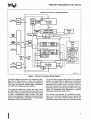
Figure 1 shows a block diagram of the Pentium processor 75/90/100/120.
For Pentium .Processor (610\75) designs which
use the TCP package,lntel document 242323
must be referenced for correct TCP pinout, mechanical, thermal, and AC specifications.
I
PENTIUM® PROCESSOR 75/90/100/120
Pentlum® Processor (75/90/100/120 MHz)
Control
Branch
Target
Bulter
64·Blt
Data
BUB
32·BII
Address
Floating
Point
Unit
BUB
Control
Data
Control
32
241997-18
Figure 1. Pentium® Processor Block Diagram
The block diagram shows the two instruction pipe·
lines, the "u" pipe and the "v" pipe. The u·pipe can
execute all integer and floating point instructions.
The v·pipe can execute simple integer instructions
and the FXCH floating·point instructions.
The separate caches are shown, the code cache
and data cache. The data cache has two ports, one
for each of the two pipes (the tags are triple ported
to allow simultaneous inquire cycles). The data
cache has a dedicated Translation Lookaside Buffer
(TLB) to translate linear addresses to the physical
addresses used by the data cache.
I
The code cache, branch target buffer and prefetch
buffers are responsible for getting raw instructions
into the execution units of the Pentium processor.
Instructions are fetched from the code cache or
from the external bus. Branch addresses are reo
membered by the branch target buffer. The code
cache TLB translates linear addresses to physical
addresses used by the code cache.
The decode unit decodes the prefetched instruc·
tions so the Pentium processors can execute the
instruction. The control ROM contains the micro·
code which controls the sequence of operations that
5
PENTIUM® PROCESSOR 75/90/100/120
must be performed to implement the Pentium processor architecture. The control ROM unit has direct
control over both pipelines.
The Pentium processors contain a pipe lined floatingpoint unit that provides a significant floating-point
performance advantage over previous generations
of processors.
The architectural features introduced in this chapter
are more' fully described in the Pentium™ Family
User's Manual.
1.2 Pentium® Processor
75/90/100/120
In addition to the architecture described above for
the Pentium processor family, the Pentium processor 75/90/100/120 has additional features which
are described in this section.
The Pentium processor 75/90/100/120 offers higher performance and higher operating frequencies
than the Pentium processor 60/66. The 120-MHz
version of the Pentium processor 75/90/100/120
offers core operation at 120 MHz, external bus interface at 60 MHz, and achieves an iCOMP index of
1000, while the 100-MHz version of the Pentium
processor 75/90/100/120 offers core operation at
100 MHz, external bus interface at 50 or 66 MHz,
and achieves an iCOMP index of 815, while the
90-MHz version offers core operation at 90 MHz, external bus interface at 60 MHz, and achieves an
iCOMP index of 735, and the Pentium processor 751
90/100/120 core operates at 75 MHz and the externalbus operates at 50 MHz.
Symmetric dual processing in a system is supported
with two Pentium processors 75/901100/120. The
, two processors appear to the system as a single
Pentium processor 75/90/100/120. Operating systems with dual processing support properly schedule
computing tasks between the two processors. This
scheduling of tasks is transparent to software applications and the end-user. Logic built into the processors support a "glueless" interface for easy system
design. Through a private bus, the two Pentium
processors 75/90/100/120 arbitrate for the external
bus and maintain cache coherency. Dual process-
6
Ing Is supported in a system only if both processors are operating at identical core and bus frequencies. Within these restrictIons, two processors of different stepplngs may operate togeth~
er In' a system.
in this document, in order to distinguish between two
Pentium processors. 75/90/1001120 in dual processing mode, one CPU will be designated as the
Primary processor with the other being the Dual
processor. Note that this is a different concept than
that of "master" and "checker" processors described above in the discussion on functional redundancy.
Due to the advanced 3.3V SiCMOS process that it is
produced on, the Pentium processor 75/90/1001
120 dissipates less power than the Pentium processor 60/66. In addition to the SMM features described above, the Pentium processor 75/90/1001
120 supports clock control. When the clock to the
Pentium processor 75/90/100/120 is stopped, power dissipation is virtually eliminated. The combination
of these improvements makes the Pentium processor 75/90/100/120 a good choice for energy-efficient desktop designs.
Supporting an upgrade socket (Socket 5) in the system will provide end-user upgradability by the addition of a Future Pentium OverDrive processor. Typical applications will realize a 40%-70% performance increase by addition of a Future Pentium
OverDrive processor.
The Pentium processor 75/90/100/120 supports
fractional bus operation. This allows the internal
processor core to operate at high frequencies, while
communicating with the external bus at lower frequencies. The external bus frequency operates at a
selectable one-half or two-thirds fraction of the internal core frequency.
The Pentium processor 75/901100/120 contains an
on-chip Advanced Programmable Interrupt Controller (APIC). This APIC implementation supports multiprocessor interrupt management (with symmetric interrupt distribution across all processors), multiple
I/O subsystem support, 8259A compatibility, and inter-processor interrupt supp'ort.
I
PENTIUM® PROCESSOR 75/90/100/120
intel®
2.0
PINOUT
2.1 Pinout and Pin Descriptions
2.1.1 PENTIUM® PROCESSOR 75/90/100/120 PINOUT
:r1 .. 35 34 33 31 31 30 ZI 21 27
AN
All!
AL
AK
AJ
AH
AG
0
vce
0
vee
AD
Ae
Al4
vss
!WI
vss
0
0
vss
vee
0
vee
0
0
0
FReye.
0
14 23 22 II
0
0
vee
10 11
0
,. 17
0
111114111211
0
0
0
vee
10
0
I
0
•
7
I
I
0
2
0
He
1
0
vee
0
He
0
on
31 34
0
Ae
vee
AB
0
vee
TOP SIDE VIEW
0
0
0
0
IIP:I
0
vss
BPI
DI.
0
0
011
0
021
0
DID
31 3D
0
024
0
0
iSS
0
0
Oil
0
D2I
0
0
iSS
vee
vee
21
28 27 21
0
02.
DP2
0
0
021
DIG
0
027
0
VSS
0
0
vee
vee
26 24
0
23
YSS
0
0
iSS
vee
zz
0
DZI
II 20
0
DPS
0
021
0
iSS
0
vee
0
DIS
D3II
0
OIl
0
0
iSS
vee
11 18 17
0
0
11
iSS
0
vee
14
13
0
040
0
D••
0
0
01.
0
VBB
vee
11
0
027
0
DI.
0
0
OIl
0
vss
vee
12 11
10
0
iSS
vss
vee
•
7
0
Oil
0
041
I
Q
0
vee
0
047
0
vee
l
0
vee
J
0
vee
G
0
Dl4
E
0
INC
e
0
INC
0
0
041
A
INC
4
N
II
0
010
0
043
I
0
vee
0
DPI
0
041
0
0
0
vee
I
0
DP4
s
0
0
Dli
0
048
0
044
0
vee
iSS
0
061
Opt
0
041
0
D41
0
DPI
vss
Dl7
0
OS3
u
iSS
0
Dli
0
W
0
0
0
FERR' PIIDBPD
0
0
EIIRt
iSS
0
0
DP7
DS3
0
0
Dl2
iSS
0
0
DID
Dll
0
0
D22
31
vee
vss
0
0
Dli
Y
0
0
0
CAeHE. vee
0
IIUO.
DII
0
EWBE.
0
INV
AA
YSS
PII18P1
33
AF
0
AE
vee
AD
0
BRDYt
AHOLD
0
epuTYP
He
0
KEN'
iSS
37 31
0
0
0
TRBTt
0
TIIS
0
0
0
Till
TOO
vee
0
0
iSS
Tel
0
0
0
vee
vee
PleDI
0
0
DO
YSS
0
0
0
vee
PleDD
D2
0
0
PleeLI
YSS
0
0
0
vee
01
03
0
0
D4
D&
0
0
0
vee
01
07
0
0
0
OPe
DI
Oil
0
0
0
0
D.
DID
014
017
0
0
0
013
011
01.
0
0
0
0
0
0
iSS
vee
BOFFI
vss
0
0
0
NA. BRDve.
vee
0
BF
He
iSS
0
HOLD
0
0
WBlWTt PHITt
INIT
vss
Y
3
S.,Acn
-0
0
peHI'
vss
0
0
. APeHI. PBREQ.
0
0
PBONTO iSS
0
0
PRDY PHITII.
0
AU
0
vss BTPeLK.
0
0
0
vee
vss
vee
0
0
vee
0
0
0
vee
He
He
0
0
Q
4
peD
A27
PfIU
0
He
0
0
vee
0
NYI
1GNNEI
vss
0
vee
0
Sill'
0
vss
0
AU
INTH
0
RBI
0
0
vee
W
0
All
0
0
0
vee
AB
AA
0
AI
0
AF
AE
21 21
0
0
0
0
AN
He
vee
vee
vee
vee
vee FLUSH.
INC
YSS
INC
INC
vee
vee
0
0
0
0
0
0
0
0
0
0
0
0
0
0
0
0
0
0
All!
AID
M
AI
VSS
VSS
VSS
VSS
VSS
VSS
VSS
VSS
VSS
VSS
YSS
WJR. EADSI ADse.
YSS
0
0
0
0
0
0
0
0
0
0
0
0
0
0
0
0
0
0
AL
0
A3
YSS
A7
AI1
All
A14
All
AID
NC
seYC
BEll BE4I BEl.
INC
BEO' BUSCHIC. HITII' PWT
AI'
0
0
0
0
0
0
0
0
0
0
0
0
0
0
0
0
0
0
AK
A2I
All
AI
AI
A13
A17
IESET
ell
BEn
DEli
BU.
BEll A2DY. HITt
DC.
AP
All
All
0
0
0
0
0
0
AJ
All
YSS
A31
AOII
HLDA BREQ
0
0
0
0
AH
All
Al2
lOCK.
YII
0
0
0
0
0
0
AG
0
3
2
1
241997-19
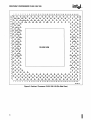
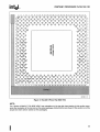
Figure 2. Pentium® Processor 75/90/100/120 Pinout (Top Side View)
I
7
PENTIUM® PROCESSOR 75/90/100/120
AN
All
AL'
1 2
3
0
0
INC
0
0
AP
0
I
7
I
0
INC
E3s. 0
0
PWT
INC
AJ
5
0
INC
AD~e.
AK
4
FLUSH.
w'Aw
,
11 11 12 13 14 15 11 17 l'
0
vee
v?s
0
0
0
vee
v?s
0
HITU, BUICHKI BEOI
0
0
DC.
HITt
0
0
A2OM.
0
lEV
0
vcc
v?s
BEll
0
0
0
v~s
BE4.
au.
vee
0
3&
0
BEll
0
BEll
vec
0
v?s
ICYC
0
BE7.
11 20 21 22 23 24
25 21
0
0
YeC
0
0
~
vce
Ne
0
elK
0
IIE8U
0
Ala
0
0
v?s
vcc
0
v~
AI.
0
AU
0
A17
vec
0
Al&
27 28 21 3D 31 32 33 34 35 31 37
0
v?s
vcc
0
A14
0
A15
0
0
vec
3& 0 &
All
0
A13
0
AI
AIO
0
0
AI
0
A7
A11
0
AI
0
A2t
0
All
vaa
Locn
0
0
sUllcn PCD
0
0
VBS
PCHKI
AE 0
0
0
vce PBREQ, APCHKI
AD
0
0
VBS PBGNTt
AC 0
0
0
vec PHITII. PROf
AD
0
0
VBS
HOLD
AF
AA
0
vee
0
0
0
A30
0
AI
0
AS
BREa ILDA ADSI
AH
0
0
AG
0
He
0
AI
0
....
0
0....
o
IHTR
NUl
0
Y88
0
0
Y88
0
Y88
0
VCC
0
VCC
0
YSS
RBI
o
0
YCC
0
SMIt
o
All
0
A21
Al3
0
Al4
o
o
0
Ali
0
0
A27
o
0
AI.
0
Y88
Y88
0
INIT
f
000
BF FRClle. yee
o
0
Ne
Y88
o
0
0
He
He
YCC
o
0
srPCLKt Y88
000
0
vce
0
o
NA'
0
VBS
BRDYI
WOO
0
VCC EWDEI KENt
o
0
U
o
I
a
N
II
L
J
G
0
vee
0
vee
0
YSS
o
vn
0
II~OI
0
BPI
VBI
0
EARl
0
013
0
VIS
0
0
vee
0
o
YSS
0
VBS
vcc
0
DU
0
CO
DPI
0
OSO
~
0
0&1
0
0&7
0
055
0
Oil
0
0
OSt
0
DSI
0
D51
0
Dn
I~C
2
I~C
3
o
o
vee
AP
AE
AD
AC
AA
W
0
0
V88
0
VCC
0
VCC
0
PlCOI
0
VCC
o
0
DO
Y88
000
01
vee
0
058
PlCOO
0
D51
03
o
0
OPi
0
D44
0~1
5
AG
I
o
0
1146
o
0
0
o
D5
01
0
yce
0
114
0
v~e
7
v~
8
v~e
,
&
v~e
&
v'i.
v~c
10 11 12 13
v~e
&
w
v~c
,&
v~c
&
w
v?c
14 15 l' 17 11 U 20 II
vi
v'is
v?c
v~c
,&
~
,?e
Z2 13 14 15 21 27 2.
~
DY.
:0
v?e
o?2
21 30 31 32
D?'
n
~5
OYI
Q
II
L
I
Q
0
1141
07
01
vce
0
00000000000000
040
~
~
~
~
~
~
~
~
~
~
DO
~
0000000000000000
ffi
~
m ~ ~ ~ ~
~
~
~
m m ~ ~ 01
w
•
R
H
0
Y88
PlceLK
v
YCC
CPUTYP
o
0
010
0
00
AJ
AH
0
T118
Y88
000
TOO
TDI
VCC
o
0
TCK
Y88
0
0P7
0
1148
o
yee
0
V88
0
He
NC.
TRSTt
o?3 &
4
o
He
0
OU
~
A
1
IIPJ
V88
YCC
o
0
0
o
vec
yee
vee
PII1BPI
0
0
PMOBPO FERR'
0
E
PIN SIDE VIEW
0 vn 0 AHOLD 0
vce CAeHEI INY
AI
0
V88
I'EIII
0
BROYc,
o
AL
AD
0
VCC
PHITt WBINT.
ZOO
VIS
DOFF.
IONNEI
AN
All
o
e
B
~
A
34 35 36 37
241997-3
Figure 3. Pentium® Processor 75/90/100/120 (Pin Side View)
8
I
PENTIUM® PROCESSOR 75/90/100/120
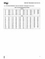
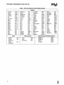
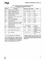
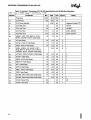
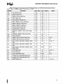
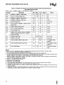
2.1.2 PIN CROSS REFERENCE TABLE FOR PENTIUM® PROCESSOR 75/90/100/120
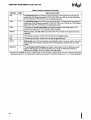
Table 1. Pin Cross Reference by Pin Name
Address
A3
A4
A5
A6
A7
A8
AL35
AM34
AK32
AN33
AL33
AM32
A9
A10
A11
A12
A13
A14
AK30
AN31
AL31
AL29
AK2B
AL27
A15
A16
A17
A1B
A19
A20
00
01
02
03
04
05
06
07
08
09
010
011
012
K34
G35
J35
G33
F36
F34
E35
E33
034
C37
C35
B36
032
013
014
015
016
017
01B
019
020
021
022
023
024
025
B34
C33
A35
B32
C31
A33
02B
B30
C29
A31
026
C27
C23
026
027
02B
029
030
031
032
033
034
035
D36
037
03B
AK26
AL25
AK24
AL23
AK22
AL21
A21
A22
A23
A24
A25
A26
AF34
AH36
AE33
AG35
AJ35
AH34
A27
A28
A29
A30
A31
AG33
AK36
AK34
AM36
AJ33
039
040
041
042
043
044
045
046
047
04B
049
050
051
010
008
A05
E09
B04
006
C05
E07
C03
004
E05
002
F04
052
053
054
055
056
057
05B
059
060
061
062
063
E03
G05
E01
G03
H04
J03
J05
K04
L05
L03
M04
N03
Data
I
024
C21
022
C19
020
C17
C15
016
C13
014
C11
012
C09
9
PENTIUM® PROCESSOR 75/90/100/120
Table 1. Pin Cross Reference by Pin Name (Contd.)
Control
A20M#
ADS#
ADSC#
AHOLD
AP
APCHK#
BEO#
BE1#
BE2#
BE3#
BE4#
BE5#
BE6#
BE?#
BOFF#
BP2
BP3
BRDY#
AK08
AJ05
AM02
V04
AK02
AE05
AL09
AK10
AL11
AK12
AL13
AK14
AL15
AK16
Z04
S03
S05
X04
10
YO;3
AJ01
ALO?
U03
035
AK04
AE35
036
030
C25
018
CO?
F06
F02
N05
AM04
W03
005
Clock Control
APIC
PICCLK
PICDO
[DPEN#]
PICD1
[APICEN]
BRDYC#
BREO
BUSCHK#
CACHE#
CPUTYP
D/C#
D/P#
DPO
DP1
DP2
DP3
DP4
DP5
DP6
DP?
EADS#
EWBE#
FERR#
H34
J33
L35
CLK
[BF]
STPCLK#
AK18
Y33
V34
FLUSH #
FRCMC#
HIT#
HITM#
HLDA
HOLD
IERR#
IGNNE#
INIT
INTR/LINTO
INV
KEN#
LOCK#
M/IO#
NA#
NMI/LlNT1
PCD
PCHK#
ANO?
Y35
AK06
AL05
AJ03
AB04
P04
AA35
AA33
AD34
U05
W05
AH04
T04
Y05
AC33
AG05
AF04
PEN#
PMO/BPO
PM1/BP1
PRDY
PWT
RIS#
RESET
SCYC
SMI#
SMIACT#
TCK
TOI
TOO
TMS
TRST#
W/R#
WB/WT#
Z34
003
R04
AC05
AL03
AC35
AK20
AL17
AB34
AG03
M34
N35
N33
P34
033
AM06
AA05
Dual Processor Private Interface
PBGNT#
PBREO#
PHIT#
PHITM#
AD04
AE03
AA03
AC03
I
PENTIUM® PROCESSOR 75/90/100/120
Table 1. Pin Cross Reference by Pin Name (Contd.)
Vee
A07
A09
A11
A13
A15
A17
A19
A21
A23
A25
A27
A29
E37
G01
G37
J01
J37
L01
L33
L37
N01
N37
Q01
Q37
501
537
T34
U01
U33
U37
W01
W37
V01
V37
AA01
AA37
AC01
AC37
AE01
AE37
AG01
AG37
AN09
AN11
AN13
AN15
AN17
AN19
AN21
AN23
AN25
AN27
AN29
Vss
806
808
810
812
814
816
818
820
822
824
826
828
H02
H36
K02
K36
M02
M36
P02
P36
R02
R36
T02
T36
U35
V02
V36
X02
X36
Z02
Z36
A802
A03
A37
802
C01
R34
533
535
W33
W35
X34
A836
AD02
AD36
AF02
AF36
AH02
AJ37
AL37
AM08
AM10
AM12
AM14
AM16
AM18
AM20
AM22
AM24
AM26
AM28
AM30
AN37
AL01
AL19
AN01
AN03
AN05
AN35
NCIINC
2.2 Design Notes
For reliable operation, always connect unused inputs to an appropriate signal level. Unused active
low inputs should be connected to Vee. Unused active HIGH inputs should be connected to GND.
No Connect (NG) pins must remain unconnected.
Connection of NC pins may result in component failure or incompatibility with processor steppings.
2.3 Quick Pin Reference
This section gives a brief functional description of
each of the pins. For a detailed description, see the
"Hardware Interface" chapter in the Pentium™t
Family User's Manual, Volume 1. Note that all input
pins must meet their AC/DC specifications to
guarantee proper functional behavior.
I
The # symbol at the end of a signal name indicates
that the active, or asserted state occurs when the
signal is at a low voltage. When a # symbol is not
present after the signal name, the signalis active, or
asserted at the high voltage level.
The following pins exist on the Pentium processor
60/66 but have been removed from the Pentium
processor 75/90/100/120:
o 18T, IU, IV, 8TO-3
The following pins become I/O pins when two
Pentium processors 75/90/100/120 are operating
in a dual processing environment:
• AD5#, CACHE#, HIT#, HITM#, HLDA#,
LOCK#, MIIO#, D/C#, W/R#, 5CVC
11
PENTIUM® PROCESSOR 75/90/100/120
Table 2. Quick Pin Reference
Symbol
A20M#
Type'
Name and Function
I
When the address bit 20 mask pin is asserted, the Pentium® processor 75/901
100/120 emulates the address wraparound at 1 Mbyte which occurs on the 8086.
When A20M# is asserted, the Pentium processor 75/90/100/120 masks physical
address bit 20 (A20) before performing a lookup to the internal caches or driving a
memory cycle on the bus. The effect of A20M # is undefined in protected mode.
A20M# must be asserted only when the processor is in real mode.
A20M# is internally masked by the Pentium processor 75/90/100/120 when
configured as a Dual processor.
A31-A3
110
As outputs, the address lines of the processor along with the byte enables define
the physical area of memory or 110 accessed. The external system drives the
inquire address to the processor on A31-A5.
ADS#
0
The address status indicates that a new valid bus cycle is currently being driven
by the Pentium processor 75/90/100/120.
ADSC#
0
ADSC# is functionally identical to ADS #.
AHOLD
I
In response to the assertion of address hold, the Pentium processor 75/90/1001
120 will stop driving the address lines (A31-A3), and AP in the next clock. The rest
of the bus will remain active so data can be returned or driven for previously issued
bus cycles.
110
Address parity is driven by the Pentium processor 75/90/100/120 with even
parity information on all Pentium processor 75/90/100/120 generated cycles in the
same clock that the address is driven. Even parity must be driven back to the
Pentium processor 75/90/100/120 during inquire cycles on this pin in the same
clock as EADS # to ensure that correct parity check status is indicated by the
Pentium processor 75/90/100/120.
AP
APCHK#
0
The address parity check status pin is asserted two clocks after EADS# is
sampled active if the Pentium processor 75/90/100/120 has detected a parity
error on the address bus during inquire cycles. APCHK # will remain active for one
clock each time a parity error is detected (including during dual processing private
snooping).
[APICEN]
PICD1
I
Advanced Programmable Interrupt Controller Enable is a new pin that enables
or disables the on-chip APIC interrupt controller. If sampled high at the falling edge
of RESET, the APIC is enabled. APICEN shares a pin with the Programmable
Interrupt Controller Data 1 signal.
0
110
The byte enable pins are used to determine which bytes must be written to
external memory, or which bytes were requested by the CPU for the current cycle.
The byte enables are driven in the same clock as the address lines (A31-3).
BE7#-BE5#
BE4#-BEO#
Unlike the Pentium processor 60/66, the lower 4-byte enables (BE3#-BEO#) are
used on the Pentium processor 75/90/100/120 as APIC ID inputs and are sampled
at RESET. After RESET, these behave exactly like the Pentium processor 60/66
byte enables.
In dual processing mode, BE4# is used as an input during Flush cycles.
12
I
PENTIUM® PROCESSOR 75/90/100/120
Table 2. Quick Pin Reference (Contd.)
Type'
Name and Function
[BF]
Symbol
I
Bus Frequency determines the bus-to-core frequency ratio. BF is sampled at
RESET, and cannot be changed until another non-warm (1 ms) assertion of RESET.
Additionally, BF must not change values while RESET is active. For proper
operation of the Pentium processor 75/90/100/120 this pin should be strapped high
or low. When BF is strapped to Vee, the processor will operate at a 2/3 bus/core
frequency ratio. When BF is strapped to Vss, the processor will operate at a 1/2
bus/core frequency ratio. If BF is left floating, the Pentium processor 75/90/100/
120 defaults to a 2/3 bus ratio. Note that core operation at either 75 MHz or 90 MHz
does not allow 1/2 bus/core frequency, while core operation at 120 MHz does not
allow 2/3 bus core frequency.
BOFF#
I
The backoff input is used to abort all outstanding bus cycles that have not yet
completed. In response to BOFF #, the Pentium processor 75/90/100/120 will float
all pins normally floated during bus hold in the next clock. The processor remains in
bus hold until BOFF# is negated, at which time the Pentium processor 75/90/100/
120 restarts the aborted bus cycle(s) in their entirety.
BP[3:2]
PM/BP[1:0]
0
The breakpoint pins (BP3-0) correspond to the debug registers, DR3-DRO. These
pins externally indicate a breakpoint match when the debug registers are
programmed to test for breakpoint matches.
BP1 and BPO are multiplexed with the performance monitoring pins (PM1 and
PMO). The PB1 and PBO bits in the Debug Mode Control Register determine if the
pins are configured as breakpoint or performance monitoring pins. The pins come
out of RESET configured for performance monitoring.
BRDY#
I
The burst ready input indicates that the external system has presented valid data
on the data pins in response to a read or that the external system has accepted the
Pentium processor 75/90/100/120 data in response to a write request. This signal
is sampled in the T2, T12 and T2P bus states.
BRDYC#
I
This signal has the same functionality as BRDY #.
BREQ
0
The bus request output indicates to the external system that the Pentium processor
75/90/100/120 has internally generated a bus request. This signal is always driven
whether or not the Pentium processor 75/90/100/120 is driving its bus.
BUSCHK#
I
The bus check input allows the system to signal an unsuccessful completion of a
bus cycle. If this pin is sampled active, the Pentium processor 75/90/100/120 will
latch the address and control signals in the machine check registers. If, in addition,
the MCE bit in CR4 is set, the Pentium processor 75/90/100/120. will vector to the
machine check exception.
CACHE#
0
For Pentium processor 75/90/1 00/120-initiated cycles the cache pin indicates
internal cacheability of the cycle (if a read), and indicates a burst write back cycle (if
a write). If this pin is driven inactive during a read cycle, the Pentium processor 75/
90/100/120 will not cache the returned data, regardless of the state of the KEN #
pin. This pin is also used to determine the cycle length (number of transfers in the
cycle).
I
13
PENTIUM® PROCESSOR 75/90/100/120
Table 2. Quick Pin Reference (Contd.)
Symbol
ClK
TypeI
Name and Function
The clock input provides the fundamental timing for the Pentium processor 75/90/
100/120. Its frequency is the operating frequency of the Pentium processor 75/90/
100/120 external bus, and requires TTL levels. All external timing parameters except
TDI, TDO, TMS, TRST #, and PICDO-1 are specified with respect to the rising edge of
ClK.
NOTE:
It is recommended that CLK begin toggling within 150 ms after Vee reaches its
proper operating level. This recommendation is only to ensure long-term
reliability of the device.
CPUTYP
I
CPU type distinguishes the Primary processor from the Dual processor. In a single
processor environment, or when the Pentium processor 75/90/100/120 is acting as
the Primary processor in a dual processing system, CPUTYP should be strapped to
Vss. The Dual processor should have CPUTYP strapped to Vee. For the Future
Pentium OverDrive processor, CPUTYP will be used to determine whether the bootup
handshake protocol will be used (in a dual socket system) or not (hi a single socket
system).
D/C#
0
The data/code output is one of the primary bus cycle definition pins. It is driven valid
in the same clock as the ADS# signal is asserted. D/C# distinguishes between data
and code or special cycles.
D/P#
0
The dual/primary processor indication. The Primary processor drives this pin low
when it is driving the bus, otherwise it drives this pin high. D/P# is always driven.
D/P# can be sampled for the current cycle with ADS# (like a status pin). This pin is
defined only on the Primary processor.
D63-DO
110
These are the 64 data lines for the processor. Lines D7 -DO define the least significant
byte of the data bus; lines D63-D56 define the most significant byte of the data bus.
When the CPU is driving the data lines, they are driven during the T2, T12, or T2P
clocks for that cycle. During reads, the CPU samples the data bus when BRDY # is
returned.
DP7-DPO
110
These are the data parity pins for the processor. There is one for each byte of the
data bus. They are driven by the Pentium processor 75/90/100/120 with even parity
information on writes in the same clock as write data. Even parity information must be
driven back to the Pentium processor 75/90/100/120 on these pins in the same clock
as the data to ensure that the correct parity check status is indicated by the Pentium
processor 75/90/100/120. DP7 applies to D63-56, DPO applies to D7-0.
[DPEN#]
PICDO
110
Dual processing enable is an output of the Dual processor and an input of the
Primary processor. The Dual processor drives DPEN # low to the Primary processor at
RESET to indicate that the Primary processor should enable dual processor mode.
DPEN # may be sampled by the system at the falling edge of RESET to determine if
Socket 5 is occupied. DPEN # shares a pin with PICDO.
EADS#
I
This signal indicates that a valid external address has been driven onto the Pentium
processor 75/90/100/120 address pins to be used for an inquire cycle.
EWBE#
I
The external write buffer empty input, when inactive (high), indicates that a write
cycle is pending in the external system. When the Pentium processor 75/90/100/120
generates a write, and EWBE# is sampled inactive, the Pentium processor 75/90/
100/120 will hold off all subsequent writes to all E- or M-state lines in the data cache
until all write cycles have completed, as indicated by EWBE# being active.
14
I
PENTIUM® PROCESSOR 75/90/100/120
Table 2. Quick Pin Reference (Contd.)
Symbol
Type·
Name and Function
FERR#
0
The floating point error pin is driven active when an unmasked floating point error
occurs. FERR # is similar to the ERROR # pin on the Intel387™ math coprocessor.
FERR # is included for compatibility with systems using DOS type floating point error
reporting. FERR # is never driven active by the Dual processor.
FLUSH#
I
When asserted, the cache flush input forces the Pentium processor 75/90/100/120
to write back all modified lines in the data cache and invalidate its internal caches. A
Flush Acknowledge special cycle will be generated by the Pentium processor 75/90/
100/120 indicating completion of the write back and invalidation.
If FLUSH # is sampled low when RESET transitions from high to low, tristate test
mode is entered.
If two Pentium processors 75/90/100/120 are operating in dual processing mode in a
system and FLUSH # is asserted, the Dual processor will perform a flush first (without
a flush acknowledge cycle), then the Primary processor will perform a flush followed
by a flush acknowledge cycle.
FRCMC#
I
The functional redundancy checking master/checker mode input is used to
determine whether the Pentium processor 75/90/100/120 is configured in master
mode or checker mode. When configured as a master, the Pentium processor 75/90/
100/120 drives its output pins as required by the bus protocol. When configured as a
checker, the Pentium processor 75/90/1 00/120 tristates all outputs (except IERR #
and TOO) and samples the output pins.
The configuration as a master/checker is set after RESET and may not be changed
other than by a subsequent RESET.
HIT#
0
The hit indication is driven to reflect the outcome of an inquire cycle. If an inquire cycle
hits a valid line in either the Pentium processor 75/90/100/120 data or instruction
cache, this pin is asserted two clocks after EADS# is sampled asserted. If the inquire
cycle misses the Pentium processor 75/90/100/120 cache, this pin is negated two
clocks after EADS#. This pin changes its value only as a result of an inquire cycle and
retains its value between the cycles.
HITM#
0
The hit to a modified line output is driven to reflect the outcome of an inquire cycle. It
is asserted after inquire cycles which resulted in a hit to a modified line in the data
cache. It is used to inhibit another bus master from accessing the data until the line is
completely written back.
HLDA
0
The bus hold acknowledge pin goes active in response to a hold request driven to
the processor on the HOLD pin. It indicates that the Pentium processor 75/90/100/
120 has floated most of the output pins and relinquished the bus to another local bus
master. When leaving bus hold, HLDA will be driven inactive and the Pentium
processor 75/90/100/120 will resume driving the bus. If the Pentium processor 75/
90/100/120 has a bus cycle pending, it will be driven in the same clock that HLDA is
de-asserted.
I
15
intet~
PENTIUM® PROCESSOR 75/90/100/120
Table 2. Quick Pin Reference (eontd.)
Type·
Name and Function
HOLD
I
In response to the bus hold request, the Pentium processor 75/90/100/120 will
float most of its output and input/output pins and assert HLDA after completing all
outstanding bus cycles. The Pentium processor 75/90/100/120 will maintain its bus
in this state until HOLD is de-asserted. HOLD is not recognized during LOCK cycles.
The Pentium processor 75/90/100/120 will recognize HOLD during reset.
IERR#
0
The internal error pin is used to indicate two types of errors, internal parity errors
and functional redundancy errors. If a parity error occurs on a read from an internal
array, the Pentium processor 75/90/100/120 will assert the IERR# pin for one
clock and then shutdown. If the Pentium processor 75/90/100/120 is configured as
a checker and a mismatch occurs between the value sampled on the pins and the
corresponding value computed internally, the Pentium processor 75/90/100/120
will assert IERR # two clocks after the mismatched value is returned.
IGNNE#
I
This is the ignore numeric error input. This pin has no effect when the NE bit in
CRO is set to 1. When the CRO.NE bit is 0, and the IGNNE# pin is asserted, the
Pentium processor 75/90/1 00/120 will ignore any pending unmasked numeric
exception and continue executing floating-point instructions for the entire duration
that this pin is asserted. When the CRO.NE bit is 0, IGNNE # is not asserted, a
pending unmasked numeric exception exists (SW.ES = 1), and the floating point
instruction is one of FINIT, FCLEX, FSTENV, FSAVE, FSTSW, FSTCW, FENI,
FDISI, or FSETPM, the Pentium processor 75/90/100/120 will execute the
instruction in spite of the pending exception. When the CRO.NE bit is 0, IGNNE# is
not asserted, a pending unmasked numeric exception exists (SW.ES = 1), and the
floating-point instruction is one other than FINIT, FCLEX, FSTENV, FSAVE,
FSTSW, FSTCW, FENI, FDISI, or FSETPM, the Pentium processor 75/90/100/120
will stop execution and wait for an external interrupt.
Symbol
IGNNE# is internally masked when the Pentium processor 75/90/100/120 is
configured as a Dual processor.
INIT
I
The Pentium processor 75/90/100/120 Initialization input pin forces the Pentium
processor 75/90/100/120 to begin execution in a known state. The processor state
after INIT is the same as the state after RESET except that the internal caches,
write buffers, and floating point registers retain the values they had prior to INIT.
INIT may NOT be used in lieu of RESET after power-up.
If INIT is sampled high when RESET transitions from high to low, the Pentium
processor 75/90/100/120 will perform built-in self test prior to the start of program
execution.
INTR/UNTO
I
An active maskable Interrupt input indicates that an external interrupt has been
generated. If the IF bit in the EFLAGS register is set, the Pentium processor 75/90/
100/120 will generate two locked interrupt acknowledge bus cycles and vector to
an interrupt handler after the current instruction execution is completed. INTR must
remain active until the first interrupt acknowledge cycle is generated to assure that
the interrupt is recognized.
If the local APIC is enabled, this pin becomes local Interrupt O.
16
I
PENTIUM® PROCESSOR 75/90/100/120
Table 2. Quick Pin Reference (Contd.)
Symbol
Type·
Name and Function
INV
I
The Invalidation input determines the final cache line state (5 or I) in case of an
inquire cycle hit. It is sampled together with the address for the inquire cycle in the
clock EAD5 # is sampled active.
KEN#
I
The cache enable pin is used to determine whether the current cycle is cacheable
or not and is consequently used to determine cycle length. When the Pentium
processor 75/90/100/120 generates a cycle that can be cached (CACHE #
asserted) and KEN # is active, the cycle will be transformed into a burst line fill
cycle.
LlNTO/INTR
I
If the APIC is enabled, this pin is local Interrupt o. If the APIC is disabled, this pin is
interrupt.
LlNT1/NMI
I
If the APIC is enabled, this pin is local Interrupt 1. If the APIC is disabled, this pin is
non-maskable interrupt.
LOCK #
0
The bus lock pin indicates that the current bus cycle is locked. The Pentium
processor 75/90/100/120 will not allow a bus hold when LOCK# is asserted (but
AHOLD and BOFF # are allowed). LOCK # goes active in the first clock of the first
locked bus cycle and goes inactive after the BRDY # is returned for the last locked
bus cycle. LOCK # is guaranteed to be de·asserted for at least one clock between
back·to-back locked cycles.
M/IO#
0
The memory/input-output is one 0 f the primary bus cycle definition pins. It is
driven valid in the same clock as the AD5# signal is asserted. M/IO# distinguishes
between memory and 1/0 cycles.
NA#
I
An active next address input indicates that the external memory system is ready to
accept a new bus cycle although all data transfers for the current cycle have not yet
completed. The Pentium processor 75/90/100/120 will issue AD5# for a pending
cycle two clocks after NA# is asserted. The Pentium processor 75/90/100/120
supports up to 2 outstanding bus cycles.
NMI/LlNT1
I
The non-maskable interrupt request signal indicates that an external nonmaskable interrupt has been generated.
If the local APIC is enabled, this pin becomes local interrupt 1.
PBGNT#
1/0
Private bus grant is the grant line that is used when two Pentium processors 751
90/100/120 are configured in dual processing mode, in order to perform private bus
arbitration. PBGNT# should be left unconnected if only one Pentium processor 751
90/100/120 exists in a system.
PBREQ#
1/0
Private bus request is the request line that is used when two Pentium processors
75/90/100/120 are configured in dual processing mode, in order to perform private
bus arbitration. PBREQ# should be left unconnected if only one Pentium processor
75/90/100/120 exists in a system.
PCD
I
0
The page cache disable pin reflects the state of the PCD bit in CR3, the Page
Directory Entry, or the Page Table Entry. The purpose of PCD is to provide an
external cacheability indication on a page by page basis.
17
PENTIUM® PROCESSOR 75/90/100/120
Table 2. Quick Pin Reference (Contd.)
Symbol
PCHK#
Type'
Name and Function
0
The parity check output indicates the result of a parity check on a data read. It is
driven with parity status two clocks after BRDY # is returned. PCHK # remains low
one clock for each clock in which a parity error was detected. Parity is checked only
for the bytes on which valid data is returned.
,
When two Pentium processors 75/90/100/120 are operating in dual processing
mode, PCHK # may be driven two or three clocks after BRDY # is returned.
PEN#
I
The parity enable input (along with CR4.MCE) determines whether a machine
check exception will be taken as a result of a data parity error on a read cycle. If this
pin is sampled active in the clock a data parity error is detected, the Pentium
processor 75/90/100/120 will latch the address and control signals of the cycle
with the parity error in the machine check registers. If, in addition, the machine
check enable bit in CR4 is set to "1", the Pentium processor 75/90/100/120 will
vector to the machine check exception before the beginning of the next instruction.
PHIT#
I/O
Private hit is a hit indication used when two Pentium processors 75/90/100/120
are configured in dual processing mode, in order to maintain local cache coherency.
PHIT# should be left unconnected if only one Pentium processor 75/90/100/120
exists in a system.
PHITM#
I/O
Private modified hit is a hit indication used when two Pentium processors 75/90/
100/120 are configured in dual processing mode, in order to maintain local cache
coherency. PHITM# should be left unconnected if only one Pentium processor 75/
90/100/120 exists in a system.
PICCLK
I
The APIC interrupt controller serial data bus clock is driven into the programmable
interrupt controller clock input of the Pentium processor 75/90/100/120.
I/O
Programmable interrupt controller data lines 0-1 of the Pentium processor 75/
90/100/120 comprise the data portion of the APIC 3·wire bus. They are open·drain
outputs that require external pull-up resistors. These signals share pins with OPEN #
and APICEN.
PICDO·1
[DPEN#]
[APICEN]
PM/BP[1:0]
0
These pins function as part of the performance monitoring feature.
The breakpoint 1·0 pins are multiplexed with the performance monitoring 1-0 pins.
The PB1 and PBO bits in the Debug Mode Control Register determine if the pins are
configured as breakpoint or performance monitoring pins. The pins come out of
RESET configured for performance monitoring.
PRDY
0
The probe ready output pin indicates that the processor has stopped normal
execution in response to the R/S# pin going active, or Probe Mode being entered.
PWT
0
The page write through pin reflects the state of the PWT bit in CR3, the page
directory entry, or the page table entry. The PWT pin is used to provide an external
write back indication on a page-by-page basis.
18
I
PENTIUM® PROCESSOR 75/90/100/120
Table 2. Quick Pin Reference (Contd.)
Symbol
Type'
Name and Function
R/S#
I
The run/stop input is an asynchronous, edge-sensitive interrupt used to stop the
normal execution of the processor and place it into an idle state. A high to low
transition on the R/S# pin will interrupt the processor and cause it to stop execution
at the next instruction boundary.
RESET
I
RESET forces the Pentium processor 75/90/100/120 to begin execution at a known
state. All the Pentium processor 75/90/100/120 internal caches will be invalidated
upon the RESET. Modified lines in the data cache are not written back. FLUSH #,
FRCMC# and INIT are sampled when RESET transitions from high to low to
determine if tristate test mode or checker mode will be entered, or if BIST will be run.
SCYC
0
The split cycle output is asserted during misaligned LOCKed transfers to indicate
that more than two cycles will be locked together. This signal is defined for locked
cycles only. It is undefined for cycles which are not locked.
SMI#
I
The system management interrupt causes a system management interrupt request
to be latched internally. When the latched SMI # is recognized on an instruction
boundary, the processor enters System Management Mode.
SMIACT#
0
An active system management interrupt active output indicates that the processor
is operating in System Management Mode.
STPCLK#
I
Assertion of the stop clock input signifies a request to stop the internal clock of the
Pentium processor 75/90/100/120 thereby causing the core to consume less power.
When the CPU recognizes STPCLK #, the processor will stop execution on the next
instruction boundary, unless superseded by a higher priority interrupt, and generate a
stop grant acknowledge cycle. When STPCLK # is asserted, the Pentium processor
75/90/100/120 will still respond to interprocessor and external snoop requests.
TCK
I
The testability clock input provides the clocking function for the Pentium processor
75/90/100/120 boundary scan in accordance with the IEEE Boundary Scan interface
(Standard 1149.1). It is used to clock state information and data into and out of the
Pentium processor 75/90/100/120 during boundary scan.
I
19
PENTIUM® PROCESSOR 75/90/100/120
Table 2. Quick Pin Reference (Contd.)
Symbol
TOI
Type"
Name and Function
I
The test data input is a serial input for the test logic. TAP instructions and data are
shifted into the Pentium processor 75/90/100/120 on the TOI pin on the rising edge
of TCK when the TAP controller is in an appropriate state.
TOO
0
The test data output is a serial output of the test logic. TAP instructions and data are
shifted out of the Pentium processor 75/90/100/120 on the TOO pin on TCK's falling
edge when the TAP controller is in an appropriate state.
TMS
I
The value of the test mode select input signal sampled at the rising edge of TCK
controls the sequence of TAP controller state changes.
TRST#
I
When asserted, the test reset input allows the TAP controller to be asynchronously
initialized.
Vcc
I
The Pentium processor 75/90/100/120 has 53 3.3V power inputs.
VSS
I
The Pentium processor 75/90/100/120 has 53 ground inputs.
W/R#
0
Write/read is one of the primary bus cycle definition pins. It is driven valid in the same
clock as the AOS# signal is asserted. W/R# distinguishes between write and read
cycles.
WB/WT#
I
The write back/write through input allows a data cache line to be defined as write
back or write through on a line-by-line basis. As a result, it determines whether a
cache line is initially in the S or E state in the data cache .
..
• The pins are classified as Input or Output based on their function In Master Mode. See the Functional Redundancy
Checking section in the "Error Detection" chapter of the Pentium™ Family User's Manual, Vol. 1, for further information.
20
I
PENTIUM® PROCESSOR 75/90/100/120
2.4 Pin Reference Tables
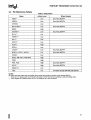
Table 3. Output Pins
Name
Active Level
When Floated
ADS#*
Low
Bus Hold, BOFF #
ADSC#
Low
Bus Hold, BOFF #
APCHK#
Low
BE7#-BE5#
Low
BREQ
High
CACHE#*
Low
D/P#**
n/a
FERR#*'
Low
HIT#*
Low
Bus Hold, BOFF #
Bus Hold, BOFF #
HITM#*
Low
HLDA*
High
IERR#
Low
LOCK#*
Low
Bus Hold, BOFF #
M/IO#*, D/C#*, W/R#*
n/a
Bus Hold, BOFF#
PCHK#
Low
BP3-2, PM1 IBP1, PMO/BPO
High
PRDY
High
PWT, PCD
High
Bus Hold, BOFF #
SCYC'
High
Bus Hold, BOFF #
SMIACT#
Low
TOO
n/a
All states except Shift-DR and Shift-IR
NOTES:
All output and input/output pins are floated during tristate test mode and checker mode (except IERR#).
• These are I/O signals when two Pentium@> processors 75/90/100/120 are operating in dual processing mode.
•• These signals are undefined when the CPU is configured as a Dual Processor.
I
21
PENTIUM® PROCESSOR 75/90/100/120
Table 4. Input Pins
Name
Active Level
Synchronousl
Asynchronous
Internal Resistor
Qualified
A20M#*
Low
Asynchronous
AHOLD
High
Synchronous
BF
High
Synchronous/RESET
BOFF#
Low
Synchronous
BRDY#
Low
Synchronous
BRDYC#
Low
Synchronous
Pullup
Bus State T2, T12, T2P
BUSCHK#
Low
Synchronous
Pullup
BRDY#
CLK
n/a
CPUTYP
High
Synchronous/RESET
EADS#
Low
Synchronous
EWBE#
Low
Synchronous
Pullup
Bus State T2, T12, T2P
BRDY#
FLUSH #
Low
Asynchronous
FRCMC#
Low
Asynchronous
HOLD
High
Synchronous
IGNNE#*
Low
Asynchronous
INIT
High
Asynchronous
INTR
High
Asynchronous
INV
High
Synchronous
EADS#
KEN #
Low
Synchronous
First BRDY#/NA#
NA#
Low
Synchronous
Bus State T2,TD,T2P
NMI
High
Asynchronous
PEN#
Low
Synchronous
PICCLK
High
Asynchronous
Pull up
RIS#
n/a
Asynchronous
Pullup
BRDY#
RESET
High
Asynchronous
SMI#
Low
Asynchronous
Pullup
STPCLK#
Low
Asynchronous
Pullup
TCK
TMS
n/a
n/a
n/a
TRST#
WB/WT#
TDI
Pullup
Synchronous/TCK
Pullup
TCK
Synchronous/TCK
Pullup
TCK
Low
Asynchronous
Pullup
n/a
Synchronous
First BRDY # INA#
• Undefined when the CPU IS configured as a Dual processor.
22
I
PENTIUM® PROCESSOR 75/90/100/120
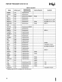
Table 5. Input/Output Pins
Qualified
(when an input)
Active
Level
When Floated
A31-A3
nfa
Address Hold, Bus Hold, BOFF #
EADS#
AP
nfa
Address Hold, Bus Hold, BOFF #
EADS#
Name
BE4#-BEO#
Low
Address Hold, Bus Hold, BOFF #
RESET
D63-DO
nfa
Bus Hold, BOFF #
BRDY#
DP7-DPO
nfa
Bus Hold, BOFF #
BRDY#
Internal
Resistor
Pulldown*
PICDO[DPEN #]
Pullup
PICD1 [APICEN]
Pulldown
NOTES:
All output and input/output pins are floated during tristate test mode (except TDO) and checker mode (except IERR# and
TDO) .
• BE3#-BEO# have Pulldowns during RESET only.
Table 6. Inter-Processor I/O Pins
Active Level
Internal Resistor
Low
Pullup
PHITM#
Low
Pullup
PBGNT#
Low
Pullup
PBREQ#
Low
Pullup
Name
PHIT#
NOTE:
For proper inter-processor operation, the system cannot load these signals.
I
23
PENTIUM® PROCESSOR 75/90/100/120
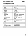
2.5 Pin Grouping According to Function
Table 7 organizes the pins with respect to their function.
Table 7. Pin Functional Grouping
Function
24
Pins
Clock
ClK
Initialization
RESET,INIT
Address Bus
A31-A3, BE7#-BEO#
Address Mask
A20M#
Data Bus
D63-DO
Address Parity
AP,APCHK#
APIC Support
PICClK, PICDO-1
Data Parity
DP7-DPO, PCHK#, PEN#
Internal Parity Error
IERR#
System Error
BUSCHK#
Bus Cycle Definition
MIIO#, D/C#, W/R#, CACHE#, SCVC, lOCK#
Bus Control
ADS#,ADSC#,BRDV#,BRDVC#,NA#
Page Cacheability
PCD,PWT
Cache Control
KEN #, WB/WT #
Cache Snooping/Consistency
AHOlD, EADS#, HIT#, HITM#, INV
Cache Flush
FlUSH#
Write Ordering
EWBE#
Bus Arbitration
BOFF#,BREQ,HOlD,HlDA
Dual Processing Private Bus Control
PBGNT#, PBREQ#, PHIT#, PHITM#
Interrupts
INTR,NMI
Floating Point Error Reporting
FERR#,IGNNE#
System Management Mode
SMI#, SMIACT#
Functional Redundancy Checking
FRCMC# (IERR#)
TAP Port
TCK, TMS, TDI, TOO, TRST #
Breakpoint/Performance Monitoring
PMO/BPO, PM1/BP1, BP3-2
Power Management
STPClK#
Miscellaneous Dual Processing
CPUTYP, D/P#
Probe Mode
RIS#, PRDV
I
PENTIUM® PROCESSOR 75/90/100/120
3.0
ELECTRICAL SPECIFICATIONS
This section describes the electrical differences between the Pentium processor 60/66 and the Pentium processor 75/90/100/120 and the DC and AC
specifications.
3.1 Electrical Differences Between
Pentium® Processor 75/90/1001
120 and Pentium Processor 60/66
Pentium® Processor
60/66 Electrical
Characteristic
Difference in
Pentium Processor
5V Power Supply
3.3V Power Supply·
5V TTL Inputs/Outputs
3.3V Inputs/Outputs
Pentium Processor
60/66 Buffer Models
Pentium Processor
75/90/100/120
Buffer Models
75/90/100/120
..
• The upgrade socket specifies two 5V Inputs (section
6.0.).
.
The sections that follow will briefly point out some
ways to design with these electrical differences.
3.1.1 3.3V POWER SUPPLY
The Pentium processor 75/90/100/120 has all Vee
3.3V inputs. By connecting all Pentium processor
60/66 Vee inputs to a common and dedicated power plane, that plane can be converted to 3.3V for the
Pentium processor 75/90/100/120.
The ClK and PICClK inputs can tolerate a 5V input
signal. This allows the Pentium processor 75/90/
100/120 to use 5V or 3.3V clock drivers.
3.1.2 3.3V INPUTS AND OUTPUTS
The inputs and outputs of the Pentium processor
75/90/100/120 are 3.3V JEDEC standard levels.
Both inputs and outputs are also TTL-compatible,
although the inputs cannot tolerate voltage swings
above the 3.3V VIN max.
For Pentium processor 75/90/100/120 outputs, if
the Pentium processor 60/66 system support components use TTL-compatible inputs, they will interface to the Pentium processor 75/90/100/120 without extra logic. This is because the Pentium processor 75/90/100/120 drives according to the 5V TTL
specification (but not beyond 3.3V).
I
For Pentium processor 75/90/100/120 inputs, the
voltage must not exceed the 3.3V VIH3 maximum
specification. System support components can consist of 3.3V devices or open-collector devices. 3.3V
support components may interface to the Pentium
processor 60/66 since they typically meet 5V TTL
speCifications. In an open-collector configuration,
the external resistor may be biased with the CPU
Vee; as the CPU's Vee changes from 5V to 3.3V, so
does this signal's maximum drive.
The ClK and PICClK inputs of the Pentium processor 75/90/100/120 are 5V tolerant, so they are
electrically identical to the Pentium processor 60/66
clock input. This allows a Pentium processor 60/66
clock driver to drive the Pentium processor 75/90/
100/120.
All pins, other than the ClK and PICClK inputs, are
3.3V-only. If an 8259A interrupt controller is used,
for example, the system must provide level converters between the 8259A and the Pentium processor
75/90/100/120.
3.1.3 3.3V PENTIUM® PROCESSOR 75/90/1001
120 BUFFER MODELS
The structure of the buffer models of the Pentium
processor 75/90/100/120 are the same as those of
the Pentium processor 60/66, but the values of the
components change since the Pentium processor
75/90/100/120 buffers are 3.3V buffers on a different process.
Despite this difference, the simulation results of
Pentium processor 75/90/100/120 buffers and Pentium processor 60/66 buffers look nearly identical.
Since the OpF AC specifications of the Pentium
processor 75/90/100/120 are derived from the
Pentium processor 60/66 specifications, the system
should see little difference between the AC behavior
of the Pentium processor 75/90/100/120 and the
Pentium processor 60/66.
To meet specifications, simulate the AC timings with
Pentium processor 75/90/100/120 buffer models.
Pay special attention to the new signal quality restrictions imposed by 3.3V buffers.
25
PENTIUM® PROCESSOR 75/90/100/120
3.2 Absolute Maximum Ratings
The values listed below are stress ratings only.
Functional operation at the maximums is not implied
or guaranteed. Functional operating conditions are
given in the AC and DC specification tables.
Extended exposure to the maximum ratings may affect device reliability. Furthermore, although the
Pentium processor 75/90/100/120 contains protective circuitry to resist damage from static electric discharge, always take precautions to avoid high static
voltages or electric fields.
Case temperature under bias ...... - 65°C to 110°C
Storage temperature .........•... - 65°C to 150°C
3V Supply voltage
with respect to Vss ............ -0.5V to + 4.6V
3V Only Buffer DC Input Voltage
- 0.5V to VCC + 0.5; not to exceed VCC3 max(2)
..
5V Safe Buffer
DC Input Voltage ............ -0.5V to 6.5V(1,3)
,. WARNING: Stressing the device beyond the '~b
solute Maximum Ratings" may cause permanent
damage. These are stress ratings only. Operation
beyond the "Operating Conditions" is not recommended and extended exposure beyond the "Operating Conditions" may affect device reliability.
3.3 DC Specifications
Tables 8,9, and 10 list the DC specifications which
apply to the Pentium processor 75/90/100/120.
The Pentium processor 75/90/100/120 is a 3.3V
part internally. The ClK and PICClK inputs may be
a 3.3V or 5V inputs. Since the 3.3V (5V-safe) input
levels defined in Table 9 are the same as the 5V TTL
levels, the ClK and PICClK inputs are compatible
with existing 5V clock driverll. The power dissipation
specification in Table 11 is provided for design of
thermal solutions during operation in a sustained
maximum level. This is the worst case power the
device would dissipate in a system. This number is
used for design of a thermal solution for the device.
NOTES:
1. Applies to ClK and PICClK.
2. Applies to all Pentium processor 75/90/1001
120 inputs except ClK and PICClK.
3. See overshoot/undershoot transient spec.
TCASE
=
0 to 70°C; VCC
Symbol
=
Table 8. 3.3V DC Preliminary Specifications
3.3V +5%
Parameter
Min
Max
Unit
Notes
TTL level(3)
VIL3
Input low Voltage
-0.3
0.8
V
VIH3
Input High Voltage
2.0
Vcc+0.3
V
TTL level(3)
VOl3
Output low Voltage
VOH3
Output High Voltage
ICC3
Power Supply Current
0.4
2.4
3700
3250
2950
2650
V
TTL level(1, 3)
V
TTL level(2, 3)
mA
mA
mA
mA
@120MHz(4)
@100MHz(4)
@90MHz(4)
@75MHz(4)
NOTES:
1. Parameter measured at 4 mAo
2. Parameter measured at 3 mAo
3. 3.3V TTL le\lels apply to all signals except ClK and PICClK.
4. This value should be used for power supply design. It was determined using a worst case instruction mix and Vee + 5%.
Power supply transient response and decoupling capacitors must be sufficient to handle the instantaneous current
changes occurring during transitions from stop clock to full active modes. For more information, refer to section 3.4.3.
26
I
PENTIUM® PROCESSOR 75/90/100/120
Table 9. 3.3V (5V-Safe) DC Specifications
Symbol
Parameter
Min
Max
Unit
Notes
VIl5
Input low Voltage
-0.3
0.8
V
TIllevel(1)
VIH5
Input High Voltage
2.0
5.55
V
TIL level(1)
NOTES:
1. Applies to ClK and PICClK only.
Table 10. Input and Output Characteristics
Symbol
Parameter
Max
Unit
Notes
15
pF
4
Output Capacitance
20
pF
4
1/0 Capacitance
25
pF
4
CClK
ClK Input Capacitance
15
pF
4
CTIN
Test Input Capacitance
15
pF
4
CTOUT
Test Output Capacitance
20
pF
4
CTCK
Test Clock Capacitance
15
pF
4
CIN
Input Capacitance
Co
CliO
Min
III
Input leakage Current
±15
p.A
ILO
Output leakage Current
±15
p.A
o < VIN < VCC3(1)
o < VIN < VCC3(1)
IIH
Input leakage Current
200
p.A
VIN = 2.4V(3)
III
Input leakage Current
-400
p.A
VIN = 0.4V(2)
NOTES:
1.
2.
3.
4.
I
This parameter is for input without pullup or pulldown.
This parameter is for input with pull up.
This parameter is for input with pulldown.
Guaranteed by design.
27
PENTIUM® PROCESSOR 75/90/100/120
Table 11. Preliminary Power Dissipation Requirements for Thermal Solution Design
Parameter
Active Power Dissipation
Typical(1)
4.7
3.9
3.5
3.0
Stop Grant and Auto Halt
Powerdown Power Dissipation
Stop Clock Power Dissipation
0.02
Max(2)
Unit
Notes
B.O
Watts
Watts
Watts
Watts
@120MHz
@100MHz
@90MHz
@75MHz
1.47
1.55
1.40
1.20
Watts
Watts
Watts
Watts
@120MHz
@100MHz(3)
@90MHz(3)
@75MHz
<0.05
Watts
4
11.9
10.1
9.0
NOTES:
1. This is the typical power dissipation in a system. This value was the average value measured in a system using a typical
device at Vee = 3.3V running typical applications. This value is highly dependent upon the specific system configuration.
2. Systems must be designed to thermally dissipate the maximum active power dissipation. It is determined using worst
case instruction mix with Vee = 3.3V and also takes into account the thermal time constants of the package.
3. Stop Grant! Auto Halt Powerdown Power Dissipation is determined by asserting the STPClK # pin or executing the HALT
instruction.
4. Stop Clock Power Dissipation is determined by asserting the STPClK# pin and then removing the external ClK input.
3.4 AC Specifications
3.4.2 POWER AND GROUND
The AC specifications of the Pentium processor 751
90/100/120 consist of setup times, hold times, and
valid delays at 0 pF.
For clean on-chip power distribution, the Pentium
processor 75/90/100/120 has 53 VCC (power) and
53 VSS (ground) inputs. Power and ground connections must be made to all external Vcc and Vss pins
of the Pentium processor 75/90/100/120. On the
circuit board all VCC pins must be connected to a
3.3V VCC plane. All VSS pins must be connected to a
VSS plane.
3.4.1 PRIVATE BUS
When two Pentium processors 75/901100/120 are
operating in dual processor mode, a "private bus"
exists to arbitrate for the CPU bus and maintain local
cache coherency. The private bus consists of two
pinout changes:
1. Five piris are added: PBREQ#,
PHIT#, PHITM#, D/P#.
PBGNT#,
2. Ten output pins become 1/0 pins: ADS#, D/C#,
W/R#, MIIO#, CACHE#, LOCK#, HIT#,
HITM#, HLDA, SCVC.
The new pins are given AC specifications of valid
delays at 0 pF, setup times, and hold times. Simulate
with these parameters and their respective 1/0 buffer models to guarantee that proper timings are met.
The AC specification gives input setup and hold
times for the ten signals that become 1/0 pins.
These setup and hold times must only be met when
a dual processor is present in the system.
2B
3.4.3 DECOUPLING RECOMMENDATIONS
Liberal decoupling capacitance should be placed
near the Pentium processor 75/90/100/120. The
Pentium processor 75/90/100/120 driving its large
address and data buses at high frequencies can
cause transient power surges, particularly when driving large capacitive loads.
Low inductance capacitors and interconnects are
recommended for best high frequency electrical performance. Inductance can be reduced by shortening
circuit board traces between the Pentium processor
75/90/100/120 and decoupling capacitors as much
as possible.
These capacitors should be evenly distributed
around each component on the 3.3V plane. Capacitor values should be chosen to ensure they eliminate both low and high frequency noise components.
I
PENTIUM® PROCESSOR 75/90/100/120
For the Pentium processor 75/90/100/120, the
power consumption can transition from a low level of
power to a much higher level (or high to low power)
very rapidly. A typical example would be entering or
exiting the Stop Grant state. Another example would
be executing a HALT instruction, causing the Pentium processor 75/90/100/120 to enter the Auto
HALT Powerdown state, or transitioning from HALT
to the Normal state. All of these examples may
cause abrupt changes in the power being consumed
by the Pentium processor 75/90/100/120. Note
that the Auto HALT Powerdown feature is always
enabled even when other power management features are not implemented.
3.4.4 CONNECTION SPECIFICATIONS
All NC and INC pins must remain unconnected.
For reliable operation, always connect unused inputs to an appropriate signal level. Unused active
low inputs should be connected to Vee. Unused active high inputs should be connected to ground.
3.4.5 AC TIMING TABLES
3.4.5.1 AC Timing Table for a 50-MHz Bus
The AC specifications given in Tables 12 and 13
consist of output delays, input setup requirements
and input hold requirements for a 50-MHz external
bus. All AC specifications (with the exception of
those for the TAP signals and APIC signals) are relative to the rising edge of the ClK input.
Bulk storage capacitors with a low ESR (Effective
Series Resistance) in the 10 to 100 pJ range are
required to maintain a regulated supply voltage during the interval between the time the current load
changes and the point that the regulated power supply output can react to the change in load. In order
to reduce the ESR, it may be necessary to place
several bulk storage capacitors in parallel.
All timings are referenced to 1.5V for both "0" and
"1" logic levels unless otherwise specified. Within
the sampling window, a synchronous input must be
stable for correct Pentium processor 75/90/1001
120 operation.
These capacitors should be placed near the Pentium processor 75/90/100/120 (on the 3.3V plane) to
ensure that the supply voltage stays within specified
limits during changes in the supply current during
operation.
Table 12. Pentium® Processor 610\75, 815\ 100 AC Specifications for 50-MHz Bus Operation
3.135 < Vee < 3.465V, TeASE = 0 to 70°C, CL = 0 pF
Symbol
Min
Max
Unit
Frequency
25.0
50.0
MHz
t1a
ClK Period
20.0
t1b
ClK Period Stability
t2
ClK High Time
t3
ClKlowTime
4.0
4
ClKFaliTime
0.15
t5
ClK Rise Time
t6a
ADS#,ADSC#, PWT, PCD,
BEO-7#, M/IO#, D/C#, CACHE#,
SCYC, W/R# Valid Delay
I
Parameter
40.0
nS
±250
pS
4.0
Figure
Notes
Max Core Freq =
100 MHz @1/2
4
1,25
nS
4
@2V,(1)
nS
4
@0.8V,(1)
1.5
nS
4
(2.0V -0.8V), (1,5)
0.15
1.5
nS
4
(0.8V-2.0V), (1,5)
1.0
7.0
nS
5
29
PENTIUM® PROCESSOR 75/90/100/120
Table 12. Pentium® Processor 610\75,815\ 100 AC Specifications for 50-MHz Bus Operation (Contd.)
3.135 < Vee < 3.465V, TeASE = 0 to 70°C, CL = 0 pF
Symbol
Min
Max
Unit
Figure
tab
AP Valid Delay
Parameter
1.0
8.5
nS
5
tae
A3-A31, LOCK# Valid Delay
1.1
7.0
nS
5
t7
ADS#, ADSC#, AP, A3-A31, PWT, PCD,
BEO-7#, M/IO#, D/C#, W/R#, CACHE#,
SCYC, LOCK # Float Delay
10.0
nS
6
1
ta
APCHK#, IERR#, FERR#, PCHK# Valid
Delay
1.0
8.3
nS
5
4
t9a
BREQ, HLDA, SMIACT # Valid Delay
1.0
8.0
nS
5
4
t10a
HIT# Valid Delay
1.0
8.0
nS
5
t10b
HITM# Valid Delay
1.1
6.0
nS
5
t11a
PMO-1, BPO-3 Valid Delay
1.0
10.0
nS
5
t11b
PRDY Valid Delay
1.0
8.0
nS
5
t12
00-063, DPO-7 Write Data Valid Delay
1.3
8.5
nS
5
Notes
~
t13
00-063, DPO-3 Write Data Float Delay
t14
A5-A31 Setup Time
t15
A5-A31 Hold Time
t16a
INV, AP Setup Time
t16b
EADS# Setup Time
t17
EADS#, INV, AP Hold Time
10.0
nS
6
1
nS
7
26
1.0
nS
7
5.0
nS
7
6.0
nS
7
1.0
nS
7
6.5
t18a
KEN # Setup Time
5.0
nS
7
t18b
NA #, WB/WT # Setup Time
4.5
nS
7
t19
KEN #, WB/WT #, NA # Hold Time
1.0
nS
7
t20
BRDY#, BRDYC# Setup Time
5.0
nS
7
t21
BRDY #, BRDYC# Hold Time
1.0
nS
7
t22
BOFF # Setup Time
5.5
nS
7
t22a
AHOLD Setup Time
6.0
nS
7
t23
AHOLD, BOFF # Hold Time
1.0
nS
7
30
I
PENTIUM® PROCESSOR 75/90/100/120
Table 12. Pentium® Processor 610\ 75, 815\ 100 AC Specifications for 50-MHz Bus Operation (Contd.)
3.135 < Vee < 3.465V, TeASE = 0 to 70·C, CL = 0 pF
Symbol
Unit
Figure
BUSCHK#, EWBE#, HOLD, PEN# Setup
Time
5.0
nS
7
t25
BUSCHK #, EWBE #, PEN # Hold Time
1.0
nS
7
t25a
HOLD Hold Time
1.5
nS
7
t26
A20M#, INTR, STPClK# Setup Time
5.0
nS
7
12,16
t27
A20M#, INTR, STPClK# Hold Time
1 .0
nS
7
13
t28
INIT, FlUSH#, NMI, SMI#,IGNNE# Setup
Time
5.0
nS
7
12,16,17
t29
INIT, FlUSH#, NMI, SMI#,IGNNE# Hold
Time
1.0
nS
7
13
t30
INIT, FlUSH#, NMI, SMI#,IGNNE# Pulse
Width, Async
2.0
ClKs
7
15,17
t31
RIS# Setup Time
5.0
nS
7
12,16,17
t32
RIS# Hold Time
1.0
nS
7
13
t33
RIS# pulse Width, Async.
2.0
ClKs
7
15,17
t34
00-063, DPO-7 Read Data Setup Time
3.8
nS
7
t35
00-063, DPO-7 Read Data Hold Time
2.0
nS
7
t36
RESET Setup Time
5.0
nS
8
11,12,16
t37
RESET Hold Time
1.0
nS
8
11,13
t38
RESET Pulse Width, Vee & ClK Stable
15
ClKs
8
11,17
t39
RESET Active After Vee & ClK Stable
1.0
mS
8
Power up
40
Reset Configuration Signals (lNIT, FlUSH#,
FRCMC#) Setup Time
5.0
nS
8
12,16,17
41
Reset Configuration Signals (INIT, FlUSH#,
FRCMC#) Hold Time
1.0
nS
8
13
t24
I
Parameter
Min
Max
Notes
31
PENTIUM® PROCESSOR 75/90/100/120
Table 12. Pentium® Processor 610\75, 815\100 AC Specifications for 50-MHz Bus Operation (Contd.)
3.135 < Vee < 3.465V, TeASE = 0 to 70·C, CL = 0 pF
Symbol
Unit
Figure
Notes
42a
Reset Configuration Signals (INIT, FLUSH #,
FRCMC#) Setup Time, Async.
Parameter
2.0
ClKs
8
To RESET falling
edge(16)
t42b
Reset Configuration Signals (INIT, FLUSH #,
FRCMC#, BRDYC#, BUSCHK#) Hold Time,
Async.
2.0
ClKs
8
To RESET falling
edge(27)
42c
Reset Configuration Signals (BRDYC # ,
BUSCHK#) Setup Time, Async.
3.0
ClKs
8
To RESET falling
edge(27)
42d
Reset Configuration Signal BRDYC# Hold
Time, RESET driven synchronously
1.0
nS
43a
BF, CPUTYP Setup Time
1.0
mS
8
To RESET falling
edge(22)
t43b
BF, CPUTYP Hold Time
2.0
ClKs
8
To RESET falling
edge(22)
t43c
APICEN Setup Time
2.0
ClKs
8
To RESET falling
edge
43d
APICEN Hold Time
2.0
ClKs
8
To RESET falling
edge
44
TCK Frequency
45
TCKPeriod
62.5
nS
4
46
TCK High Time
25.0
nS
4
t47
TCKlowTime
25.0
nS
4
@0.8V(1)
Min
Max
16.0
To RESET falling
edge(1,27)
MHz
@2V(1) ,
48
TCK Fall Time
5.0
nS
4
(2.0V -0.8V) (1,8,9)
t49
TCK Rise Time
5.0
nS
4
(0.8V -2.0V) (1,8,9)
t50
TRST # Pulse Width
40.0
nS
10
Asynchronous(1 )
t51
TDI, TMS Setup Time
5.0
nS
9
7
t52
TDI, TMS Hold Time
13.0
t53
TDO Valid Delay
t54
TDO Float Delay
t55
All Non-Test Outputs Valid Delay
32
3.0
3.0
nS
9
7
20.0
nS
9
8
25.0
nS
9
1,8
20.0
nS
9
3,8,10
I
PENTIUM® PROCESSOR 75/90/100/120
Table 12. Pentium@ Processor 610\75, 815\ 100 AC Specifications for 50-MHz Bus Operation (Contd.)
3.135 < Vee < 3.465V, TeASE = 0 to 70·C, CL = 0 pF
Symbol
Parameter
Min
Max
Unit
Figure
25.0
nS
9
1,3,6,10
Notes
t5e
All Non-Test Outputs Float Delay
t57
All Non-Test Inputs Setup Time
5.0
nS
9
3,7,10
t58
All Non-Test Inputs Hold Time
13.0
nS
9
3,7,10
teOa
PICCLK Frequency
teob
PICCLK Period
teoc
PICCLK High Time
9.0
tatld
PICCLK Low Time
9.0
teOe
teOf
teog
PICCLK Rise Time
1.0
5.0
PICCLK Fall Time
1.0
5.0
nS
4
PICDO-1 Setup Time
3.0
nS
7
ToPICCLK
APIC AC Specifications
2.0
16.66
60.0
500.0
MHz
nS
4
nS
4
nS
4
nS
4
teOh
teOi
PICDO-1 Hold Time
2.5
nS
7
ToPICCLK
PICDO-1 Valid Delay (LtoH)
4.0
38.0
nS
5
From PICCLK(28,29)
teoi
PICDO-1 Valid Delay (HtoL)
4.0
22.0
nS
5
From PICCLK(28,29)
I
33
PENTIUM® PROCESSOR 75/90/100/120
3.135
< Vee <
Symbol
Table 13. Pentlum@ Processor 610\75, 815\ 100 Dual Processor Mode
AC Specifications for 50 MHz Bus Operation
3.465V, TeASE = 0 to 70·C, CL = 0 pF
Parameter
t80a
PBREQ#, PBGNT# Valid Delay
Figure
Min
Max
Unit
Notes
1.0
5.0
nS
5
18
0
2.0
nS
11
30
taOb
PHIT#;PHITM# Flight Time
t81a
PBREQ#, PBGNT# Setup Time
8.0
nS
7
18
t82
PBREQ#, PBGNT# Hold Time
1.0
nS
7
18,24
t83a
A5-A31 Setup Time
6.5
nS
7
18,21,26
t83b
D/C#, W/R#, CACHE#, lOCK#,
SCYC Setup Time
6.0
nS
7
18,21
t83c
ADS#, M/IO# Setup Time
8.0
nS
7
18,21
ta3d
HIT#, HITM# Setup Time
8.0
nS
7
18,21
t839
HlDA Setup Time
6.0
nS
7
18,21
ta4
ADS#, D/C#, W/R#, M/IO#,
CACHE # , lOCK # ,A5-A31,
HlDA, HIT #, HITM #, SCYC Hold
Time
1.0
nS
7
18,21
tas
DPEN# Valid Time
10.0
ClKs
18,19,23
t86
DPEN # Hold Time
2.0
ClKs
t87
APIC ID (BEO#-BE3#) Setup Time
2.0
ClKs
8
To RESET falling
edge(23)
t88
APIC ID (BEO#-BE3#) Hold Time
2.0
ClKs
8
From RESET falling
edge(23)
tag
D/P# Valid Delay
1.0
nS
5
Primary Processor
Only
34
8.0
18,20,23
I
PENTIUM® PROCESSOR 75/90/100/120
3.4.5.2 AC Timing Tables for a 60-MHz Bus
The AC specifications given in Tables 14 and 15
consist of output delays, input setup requirements
and input hold requirements for a 60-MHz external
bus. All AC specifications (with the exception of
those for the TAP signals and APIC signals) are relative to the rising edge of the ClK input.
3.135
<
All timings are referenced to 1.5V for both "0" and
"1" logic levels unless otherwise specified. Within
the sampling window, a synchronous input must be
stable for correct Pentium processor 75/90/1001
120 operation.
Table 14. Pentlum@ Processor 735\90 AC Specifications for 60-MHz Bus Operation
Vee < 3.465V, TeASE = 0 to 70·C, CL = 0 pF
Symbol
Parameter
Unit
Figure
MHz
4
33.33
nS
4
±250
pS
4
Adjacent Clocks,(1,25)
4.0
nS
4
@2V(1)
4.0
nS
4
@0.8V(1)
4
(2.0V -0.8V) (1 ,5)
4
(0.8V -2.0V) (1 ,5)
Min
Max
Frequency
30.0
60.0
t1a
ClK Period
16.67
t1b
ClK Period Stability
t2
ClK High Time
t3
ClKlowTime
t4
ClKFallTime
0.15
1.5
nS
t5
ClK Rise Time
0.15
1.5
nS
tSa
ADS#, ADSC#, PWT, PCD, BEO"7#,
M/IO#, D/C#, CACHE#, SCVC,
W/R# Valid Delay
1.0
7.0
nS
5
tSb
AP Valid Delay
1.0
8.5
nS
5
1.1
tae
A3-A31, lOCK# Valid Delay
t7
ADS#, ADSC#, AP, A3-A31, PWT,
PCD, BEO-7#, M/IO#, D/C#, W/R#,
CACHE#, SCVC, lOCK# Float Delay
taa
APCHK#, IERR#, FERR# Valid Delay
tab
t9a
t9b
t10a
t10b
HITM # Valid Delay
t11a
PMO-1, BPO-3 Valid Delay
t11b
PRDV Valid Delay
t12
00-063, DPO-7 Write Data Valid Delay
I
Notes
7.0
nS
5
10.0
nS
5
1
1.0
8.3
nS
5
4
PCHK# Valid Delay
1.0
7.0
nS
5
4
BREa, HlDA Valid Delay
1.0
8.0
nS
5
4
SMIACT# Valid Delay
1.0
7.6
nS
5
HIT# Valid Delay
1.0
8.0
nS
5
1.1
6.0
nS
5
1.0
10.0
nS
5
1.0
8.0
nS
5
1.3
7.5
nS
5
35
PENTIUM® PROCESSOR 75/90/100/120
3.135
Table 14. Pentium® Processor 735\90 AC Specifications for 60-MHz Bus Operation (Contd.)
< Vee < 3.465V, TeASE = 0 to 70·C, CL = 0 pF
Symbol
Parameter
t13
00·063, DPO·3 Write Data Float Delay
t14
A5·A31 Setup Time
t15
Min
Max
10.0
Unit
Figure
Notes
nS
6
1
6.0
nS
7
26
A5·A31 Hold Time
1.0
nS
7
t16a
INV, AP Setup Time
5.0
nS
7
t16b
EADS# Setup Time
5.5
nS
7
t17
EADS#, INV, AP Hold Time
1.0
nS
7
t18a
KEN # Setup Time
5.0
nS
7
t18b
NA#, WB/WT# Setup Time
4.5
nS
7
t19
KEN#, WB/WT#, NA# Hold Time
1.0
nS
7
t20
BRDY#, BRDYC# Setup Time
5.0
nS
7
t21
BRDY#, BRDYC# Hold Time
1.0
nS
7
t22
AHOLD, BOFF # Setup Time
5.5
nS
7
t23
AHOLD, BOFF # Hold Time
1.0
nS
7
t24
BUSCHK#, EWBE#, HOLD, PEN# Setup
Time
5.0
nS
7
t25
BUSCHK#, EWBE#, PEN# Hold Time
1.0
nS
7
t25a
HOLD Hold Time
1.5
nS
7
t26
A20M#, INTR, STPCLK# Setup Time
5.0
nS
7
t27
A20M#, INTR, STPCLK# Hold Time
1.0
nS
7
13
t28
INIT, FLUSH#, NMI, SMI#, IGNNE# Setup
Time
5.0
nS
7
12,16,17
t29
INIT, FLUSH#, NMI, SMI#, IGNNE# Hold
Time
1.0
nS
7
13
t30
INIT, FLUSH#, NMI, SMI#, IGNNE# Pulse
Width, Async
2.0
CLKs
t31
RIS# Setup Time
5.0
nS
7
12,16,17
t32
RIS# Hold Time
1.0
nS
7
13
t33
RIS# Pulse Width, Async.
2.0
CLKs
7
15,17
36
12,16
15,17
I
PENTIUM® PROCESSOR 75/90/100/120
3.135
Table 14. Pentium® Processor 735\90 AC Specifications for 60-MHz Bus Operation (Contd.)
< Vee < 3.465V, TeASE = 0 to 70·C, CL = 0 pF
Symbol
Parameter
Min
Max
Unit
Figure
Notes
t34
00-063, OPO-7 Read Oata Setup Time
3.0
nS
7
t35
00-063, OPO-7 Read Oata Hold Time
2.0
nS
8
t36
RESET Setup Time
5.0
nS
8
11,12,16
t37
RESET Hold Time
1.0
nS
8
11, 13
t38
RESET Pulse Width, Vee & ClK Stable
15
ClKs
8
11, 17
t39
RESET Active After Vee & ClK Stable
1.0
mS
8
Power up
t40
Reset Configuration Signals (INIT, FLUSH #,
FRCMC#) Setup Time
5.0
nS
8
12,16,17
t41
Reset Configuration Signals (INIT, FLUSH #,
FRCMC #) Hold Time
1.0
nS
8
13
t42a
Reset Configuration Signals (INIT, FLUSH #,
FRCMC#) Setup Time, Async.
2.0
ClKs
8
To RESET falling
edge(16)
42b
Reset Configuration Signals (INIT, FLUSH #,
FRCMC#, BROYC#, BUSCHK#) Hold Time,
Async.
2.0
ClKs
8
To RESET falling
edge (27)
42c
Reset Configuration Signals (BROYC#,
BUSCHK#) Setup Time, Async.
3.0
ClKs
8
To RESET falling
edge(27)
t42d
Reset Configuration Signal BROYC# Hold
Time, RESET driven synchronously
1.0
nS
t43a
BF, CPUTYP Setup Time
1.0
mS
8
To RESET falling
edge(22)
t43b
BF, CPUTYP Hold Time
2.0
ClKs
8
To RESET falling
edge(22)
t43c
APICEN Setup Time
2.0
ClKs
8
To RESET falling
edge
t43d
APICEN Hold Time
2.0
ClKs
8
To RESET falling
edge
t44
TCK Frequency
MHz
8
t45
TCK Period
62.5
nS
4
t46
TCK High Time
25.0
nS
4
@2V(1)
t47
TCKlowTime
25.0
nS
4
@0.8V(1)
I
16.0
To RESET falling
edge(1,27)
37
PENTIUM® PROCESSOR 75/90/100/120
3.135
Table 14. Pentium® Processor 735\90 AC Specifications for SO-MHz Bus Operation (Contd.)
< Vee < 3.465V, TeASE = 0 to 70·C, CL = O.pF
Symbol
Parameter
Min
Max
Unit
Figure
Notes
48
TCKFaliTime
5.0
nS
4
(2.0V -0.8V)(1 ,8,9)
49
TCK Rise Time
5.0
nS
4
(O.8V -2.0V)(1 ,8,9)
tso
TRST # Pulse Width
40.0
nS
10
Asynchronous(1 )
tS1
TDI, TMS Setup Time
5.0
nS
9
7
tS2
TDI, TMS Hold Time
13.0
tS3
TOO Valid Delay
ts4
TOO Float Delay
tss
All Non-Test Outputs Valid Delay
3.0
3.0
nS
9
7
20.0
nS
9
8
25.0
nS
9
1,8
20.0
nS
9
3,8,10
25.0
tss
All Non-Test Outputs Float Delay
nS
9
1,3,8,10
tS7
All Non-Test Inputs Setup Time
5.0
nS
9
3,7,10
tS8
All Non-Test Inputs Hold Time
13.0
nS
9
3,7,10
APIC AC Specifications
tsoa
PICCLK Frequency
tSOb
PICCLK Period
tSOc
PICCLK High Time
tSOd
PICCLK Low Time
teOe
PICCLK Rise Time
1.0
teo!
PICCLK Fall Time
1.0
tSOg
PICDO-1 Setup Time
3.0
tSOh
PICDO-1 Hold Time
2.5
teoi
PICDO-1 Valid Delay (LtoH)
4.0
38.0
teOj
PICDO-1 Valid Delay (HtoL)
4.0
22.0
38
2.0
16.66
MHz
4
60.0
500.0
nS
4
9.0
nS
4
9.0
nS
4
5.0
nS
4
5.0
nS
4
nS
7
ToPICCLK
nS
7
ToPICCLK
nS
5
From PICCLK(28,29)
nS
5
From PICCLK(28,29)
I
PENTIUM® PROCESSOR 75/90/100/120
3.135
< Vec <
Symbol
tSOa
Table 15. Pentium® Processor 735\90 Dual Processor Mode
AC Specifications for 60-MHz Bus Operation
3A65V, TCASE = 0 to 70·C, CL = 0 pF
Parameter
PBREQ#, PBGNT# Valid Delay
tsob
PH IT #, PHITM # Flight Time
t81a
PBREQ#, PBGNT# Setup Time
Min
Max
Unit
Figure
1.0
5.0
nS
5
18
Notes
0
2.0
nS
11
30
8.0
nS
7
18
182
PBREQ#, PBGNT# Hold Time
1.0
nS
7
18,24
tS3a
A5-A31 Setup Time
3.0
nS
7
18,21,26
183b
D/C#, W/R#, CACHE#, lOCK#, SCVC
Setup Time
4.0
nS
7
18,21
tS3e
ADS#, M/IO# Setup Time
6.0
nS
7
18,21
tS3d
HIT #, HITM # Setup Time
6.0
nS
7
18,21
tS3e
HlDA Setup Time
6.0
nS
7
18,21
tS4
ADS#, D/C#, W/R#, M/IO#, CACHE#,
lOCK#, A5-A31, HlDA, HIT#, HITM#,
SCVC Hold Time
1.0
nS
7
18,21
185
DPEN # Valid Time
ClKs
18,19,23
tS6
DPEN # Hold Time
2.0
ClKs
18,20,23
tS7
APIC ID (BEO#-BE3#) Setup Time
2.0
ClKs
8
To RESET falling
edge(23)
tS8
APIC ID (BEO#-BE3#) Hold Time
2.0
ClKs
8
From RESET falling
edge(23)
tS9
D/P# Valid Delay
1.0
nS
5
Primary Processor
Only
3.4.5.3 AC Timing Tables for a 66-MHz Bus
The AC specifications given in Tables 16 and 17
consist of output delays, input setup requirements
and input hold requirements for a 66-MHz external
bus. All AC specifications (with the exception of
those for the TAP signals and AP IC signals) are
relative to the rising edge of the ClK input.
I
10.0
8.0
All timings are referenced to 1.5V for both "0" and
"1" logic levels unless otherwise specified. Within
the sampling window, a synchronous input must be
stable for correct Pentium processor 75/90/1001
120 operation.
39
PENTIUM® PROCESSOR 75/90/100/120
3.135
<
Table 16. Pentium® Processor 815\ 100 AC Specifications for 66-MHz Bus Operation
Vcc < 3.465V, TCASE = 0 to 70·C, CL = 0 pF
Symbol
Parameter
Min
Max
Unit
Frequency
33.33
66.6
MHz
t1a
ClKPeriod
15.0
30.0
nS
t1b
ClK Period Stability
±250
pS
t2
ClK High Time
4.0
nS
Figure
Notes
4
Adjacent Clocks(1,2S)
4
@2V(1)
t3
ClKlowTime
nS
4
@0.8V(1)
4
ClKFaliTime
0.15
1.5
nS
5
(2.0V-O.8V)(1)
ts
ClK Rise Time
0.15
1.5
nS
4
(0.8V-2.0V)(1)
16a
ADSC#, PWT, PCD, BEO-7#, D/C#,
W/R#, CACHE#, SCYCValid Delay
1.0
7.0
nS
5
tSb
AP Valid Delay
1.0
8.5
nS
5
16e
A3-A31, lOCK# Valid Delay
1.1
7.0
nS
5
1.0
tSd
ADS#, M/IO# Valid Delay
t7
ADS#, ADSC#, AP, A3-A31, PWT,
PCD, BEO-7#, M/IO#, D/C#, W/R#,
CACHE#, SCYC, lOCK# Float Delay
taa
APCHK#, IERR#, FERR# Valid Delay
tab
tSa
4.0
6.0
nS
5
10.0
nS
6
1
1.0
8.3
nS
5
4
PCHK# Valid Delay
1.0
7.0
nS
5
4
BREQ, HlDA Valid Delay
1.0
8.0
nS
5
4
4
tSb
SMIACT# Valid Delay
1.0
7.6
nS
5
t10a
HIT# Valid Delay
1.0
8.0
nS
5
t10b
HITM# Valid Delay
1.1
6.0
nS
5
t11a
PMO-1, BPO-3 Valid Delay
1.0
10.0
nS
5
t11b
PRDY Valid Delay
1.0
8.0
nS
5
t12
00-063, DPO-7 Write Data Valid Delay
1.3
7.5
nS
5
t13
00-063, DPO-3 Write Data Float Delay
10.0
nS
6
1
t14
A5-A31 Setup Time
6.0
nS
7
26
t15
A5-A31 Hold Time
1.0
nS
7
40
I
PENTIUM® PROCESSOR 75/90/100/120
3.135
Table 16. Pentlum® Processor 815\ 100 AC Specifications for 66-MHz Bus Operation (Contd.)
< Vee < 3.465V, TeAsE = 0 to 70·C, CL = 0 pF
Symbol
Parameter
Min
Max
Unit
Figure
t16a
INV, AP Setup Time
5.0
nS
7
t16b
EADS # Setup Time
5.5
nS
7
t17
EADS#, INV, AP Hold Time
1.0
nS
7
t18a
KEN # Setup Time
5.0
nS
7
t18b
NA #, WB/WT # Setup Time
4.5
nS
7
t19
KEN#, WB/WT#, NA# Hold Time
1.0
nS
7
t20
BRDY#, BRDYC# Setup Time
5.0
nS
7
t21
BRDY#, BRDYC# Hold Time
1.0
nS
7
t22
AHOlD, BOFF # Setup Time
5.5
nS
7
t23
AHOlD, BOFF # Hold Time
1.0
nS
7
t24
BUSCHK#, EWBE#, HOLD, PEN# Setup
Time
5.0
nS
7
t25a
BUSCHK#, EWBE#, PEN# Hold Time
1.0
nS
7
Notes
t25b
HOLD Hold Time
1.5
nS
7
t26
A20M #, INTR, STPClK # Setup Time
5.0
nS
7
t27
A20M#,INTR, STPClK# Hold Time
1.0
nS
7
13
t28
INIT, FLUSH #, NMI, SMI #, IGNNE # Setup
Time
5.0
nS
7
12,16,17
t29
INIT, FLUSH #, NMI, SMI #, IGNNE # Hold
Time
1.0
nS
7
13
t30
INIT, FlUSH#, NMI, SMI#,IGNNE# Pulse
Width, Async
2.0
ClKs
t31
RIS# Setup Time
5.0
nS
7
t32
RIS# Hold Time
1.0
nS
7
t33
RIS# Pulse Width, Async.
2.0
ClKs
t34
DO-D63, DPO·7 Read Data Setup Time
3.0
nS
7
t35
DO·D63, DPO-7 Read Data Hold Time
2.0
nS
7
t36
RESET Setup Time
5.0
nS
8
I
12,16
15,17
12,16,17
13
15,17
11,12,16
41
PENTIUM® PROCESSOR 75/90/100/120
3.135
Table 16. Pentium® Processor 815\ 100 AC Specifications for 66-MHz Bus Operation (Contd.)
< Vee < 3.465V, TeASE = 0 to 70·C, CL = 0 pF
Symbol
Parameter
t37
RESET Hold Time
t38
RESET Pulse Width, Vee & CL K Stable
Min
Max
1.0
Unit
Figure
Notes
nS
8
11,13
15.0
CLKs
8
11,17
t39
RESET Active After Vee & CLK Stable·
1.0
mS
8
Power up
t40
Reset Configuration Signals (INIT, FLUSH #,
FRCMC#) Setup Time
5.0
nS
8
12,16,17
t41
Reset Configuration Signals (INIT, FLUSH #,
FRCMC#) Hold Time
1.0
nS
8
13
42a
Reset Configuration Signals (INIT, FLUSH #,
FRCMC#) Setup Time, Async.
2.0
CLKs
8
To RESET falling
edge(16)
42b
Reset Configuration Signals (INIT, FLUSH #,
FRCMC#, SRDYC#, SUSCHK#) Hold Time,
Async.
2.0
CLKs
8
To RESET falling
edge(27)
42c
Reset Configuration Signals (SRDYC#,
SUSCHK#) Setup Time, Async.
3.0
CLKs
8
To RESET falling
edge(27)
42d
Reset Configuration Signal SRDYC# Hold
Time, RESET driven synchronously
1.0
nS
t43a
SF, CPUTYP Setup Time
1.0
mS
8
To RESET falling
edge(22)
43b
SF, CPUTYP Hold Time
2.0
CLKs
8
To RESETfalling
edge(22)
43c
APICEN Setup Time
2.0
CLKs
8
To RESET falling
edge
43d
APICEN Hold Time
2.0
CLKs
8
To RESET falling
edge
44
TCK Frequency
45
TCKPeriod
62.5
nS
4
46
TCK High Time
25.0
nS
4
@2V(1)
25.0
nS
4
@0.8V(1)
16.0
To RESET falling
edge(1,27)
MHz
47
TCKLowTime
t48
TCKFallTime
5.0
nS
4
(2.0V -0.8V)(1,8,9)
5.0
nS
4
(0.8V-2.0V)(1,8,9)
40.0
nS
10
Asynchronous(1 )
5.0
nS
9
7
49
TCK Rise Time
t50
TRST # Pulse Width
t51
TDI, TMS Setup Time
42
I
PENTIUM® PROCESSOR 75/90/100/120
3.135
Table 16. Pentlum@ Processor 815\ 100 AC Specifications for 66-MHz Bus Operation (Contd.)
< VCC < 3.465V, TCASE= 0 to 70·C, CL = 0 pF
Symbol
Parameter
Min
tS2
TDI, TMS Hold Time
tS3
TOO Valid Delay
tS4
TOO Float Delay
tss
All Non-Test Outputs Valid Delay
tss
All Non-Test Outputs Float Delay
tS7
All Non-Test Inputs Setup Time
tS8
All Non-Test Inputs Hold Time
tSOa
PICCLK Frequency
Max
13.0
Unit
Figure
nS
9
7
Notes
20.0
nS
9
8
25.0
nS
9
1,8
20.0
nS
9
3,8,10
25.0
nS
9
1,3,8,10
5.0
nS
9
3,7, 10
13.0
nS
9
3,7,10
3.0
3.0
APIC AC Specifications
2.0
16.66
60.0
500.0
tSOb
PICCLK Period
tsoc
PICCLK High Time
9.0
MHz
nS
4
nS
4
taod
PICCLK Low Time
9.0
nS
4
tsoe
PICCLK Rise Time
1.0
5.0
nS
4
t60f
PICCLK Fall Time
1.0
5.0
nS
4
tSOg
PICDO-1 Setup Time
3.0
nS
7
ToPICCLK
tsoh
PICDO-1 Hold Time
2.5
nS
7
ToPICCLK
taOi
PICDO-1 Valid Delay (LtoH)
4.0
38.0
nS
5
From PICCLK(28,29)
taOj
PICDO-1 Valid Delay (HtoL)
4.0
22.0
nS
5
From PICCLK(28,29)
I
43
PENTIUM® PROCESSOR 75/90/100/120
3.135
<
Table 17. Pentium® Processor 815\ 100 Dual Processor Mode AC Specifications
for 66-MHz Bus Operation
VCC < 3.465V, TCASE = 0 to 70·C, Cl = 0 pF
Symbol
Parameter
Min
Max
Unit
Figure
Notes
1.0
5.0
nS
5
18
0
2.0
nS
11
30
teoa
PBREQ#, PBGNT# Valid Delay
teob
PHIT#, PHITM# FlightTime
te1a
PBREQ#, PBGNT# Setup Time
8.0
nS
7
18
te2
PBREQ#, PBGNT# Hold Time
1.0
nS
7
18,24
te3a
A5·A31 Setup Time
3.0
nS
7
18,21,26
te3b
D/C#, W/R#, CACHE#, lOCK # , SCYC
4.0
nS
7
18,21
5.8
nS
7
18,21
18,21
Setup Time
te3c
ADS#, MIIO# Setup Time
te3d
HIT#, HITM# Setup Time
6.0
nS
7
te3e
HlDA Setup Time
6.0
nS
7
18,21
te4
ADS#, D/C#, W/R#, MIIO#, CACHE#,
lOCK#, A5-A31, HlDA, HIT#, HITM#,
SCYC Hold Time
1.0
nS
7
18,21
te5
OPEN # Valid Time
10.0
18,19,23
ClKs
18,20,23
te6
OPEN # Hold Time
2.0
ClKs
te7
APIC 10 (BEO#-BE3#) Setup Time
2.0
ClKs
8
To RESET falling
edge(23)
tee
APIC 10 (BEO#-BE3#) Hold Time
2.0
ClKs
8
From RESET falling
edge(23)
D/P# Valid Delay
1.0
nS
5
Primary Processor
Only
0
te9
8.0
NOTES:
Notes 2,6, and 14 are general and apply to all standard TTL signals used with the Pentium!!> Processor family.
1. Not 100% tested. Guaranteed by designl characterization.
2. TTL input test waveforms are assumed to be 0 to 3V transitions with WInS rise and fall times.
3. Non-test outputs and inputs are the normal output or input signals (besides TCK, TRST #, TDI, TDO, and TMS). These
timings correspond to the response Of these signals due to boundary scan operations.
4. APCHK#, FERR#, HlDA, IERR#, lOCK#, and PCHK# are glitch-free outputs. Glitch-free signals monotonically transition without false transitions (i.e., glitches).
5. 0.8V1ns ~ ClK input riselfall time ~ eV/ns.
6. 0.3V/ns ~ input riselfall time ~ 5V/ns.
7. Referenced to TCK rising edge.
e. Referenced to TCK falling edge.
9. 1 ns can be added to the maximum TCK rise and fall times for every 10 MHz of frequency below 33 MHz.
10. During probe mode operation, do not use the boundary scan timings (t55.5S).
11. FRCMC# should be tied to Vee (high) to ensure proper operation of the Pentium processor 75/90/100/120 as a
primary processor.
12. Setup time is required to guarantee recognition on a specific clock. Pentium processor 75/90/100/120 must meet this
specification for dual processor operation for the FLUSH # and RESET signals.
44
I
PENTIUM® PROCESSOR 75/90/100/120
13. Hold time is required to guarantee recognition on a specific clock. Pentium processor 75/90/100/120 must meet this
specification for dual processor operation for the FLUSH # and RESET signals.
14. All TTL timings are referenced from 1.5V.
15. To guarantee proper asynchronous recognition, the signal must have been de-asserted (inactive) for a minimum of
2 clocks before being returned active and must meet the minimum pulse width.
16. This input may be driven asynchronously. However, when operating two processors in dual processing mode, FLUSH #
and RESET must be asserted synchronously to both processors.
17. When driven asynchronously, RESET, NMI, FlUSH#, RIS#, INIT, and SMI# must be de-asserted (inactive) for a
minimum of 2 clocks before being returned active.
18. Timings are valid only when dual processor is present.
19. Maximum time DPEN# is valid from rising edge of RESET.
20. Minimum time DPEN # is valid after falling edge of RESET.
21. The D/C#, MIIO#, W/R#, CACHE#, and A5-A31 signals are sampled only on the ClK that ADS# is active.
22. BF and CPUTYP should be strapped to Vee or Vss.
23. RESET is synchronous in dual processing mode and functional redundancy checking mode. All signals which have a
setup or hold time with respect to a falling or rising edge of RESET in UP mode, should be measured with respect to
the first processor clock edge in which RESET is sampled either active or inactive in dual processing and functional
redundancy checking modes.
24. The PHIT# and PHITM# signals operate at the core frequency (75, 90 or 100 MHz).
25. These signals are measured on the rising edge of adjacent ClKs at 1.5V. To ensure a 1:1 relationship between the
amplitude of the input jitter and the internal and external clocks, the jitter frequency spectrum should not have any
power spectrum peaking between 500 KHz and 113 of the ClK operating frequency. The amount of jitter present must
be accounted for as a component of ClK skew between devices.
26. In dual processing mode, timing t14 is replaced by t83a. Timing t14 is required for external snooping (e.g., address setup
to the ClK in which EADS# is sampled active) in both uniprocessor and dual processor modes.
27. BRDYC# and BUSCHK# are used as reset configuration signals to select buffer size.
28. This assumes an external pull up resistor to Vee and a lumped capacitive load such that the maximum RC product does
not exceed R = 150n, C = 240 pF.
29. This assumes an external pullup resistor to Vee and a lumped capacitive load such that the minimum RC product does
not fall below R = 150n, C = 20 pF.
30. This is a flight time specification, that includes both flight time and clock skew. The flight time is the time from where the
unloaded driver crosses 1.5V (50% of min Vee), to where the receiver crosses the 1.5V level (50% of min Vee). See
Figure 11.
Each valid delay is specified for a 0 pF load. The system designer should use I/O buffer modeling to account for signal
flight time delays.
I
45
PENTIUM® PROCESSOR 75/90/100/120
2.0Y.
O.8Y.
241997-4
Tv = t5, t49, tBOe; Tw = t4, t4B, tBOf; Tx = t3, t47, tBOd
Ty = t1, t45, tBOb; Tz = t2, t4B, tsOc
Figure 4. Clock Waveform
Signal
241997-5
Tx = tB, tB, t9, t10, t11, t12, tBOi, tBO, tB9
Figure 5. Valid Delay Timings
46
I
PENTIUM® PROCESSOR 75/90/100/120
Ty
Signal
241997-6
Tx = t7, t13; Ty = t6min, t12min
Figure 6. Float Delay Timings
\'----
eLK
Tx
Signal
Ty
VALID
241997-7
Tx = t14, t16, t1 B, t20, t22, t24, t26, t2B, t31, t34, t60g (to PICCLK),tB1, tB3
Ty = t15, t17, t19, t21, t23, t25, t27, t29, t32, t35, t60h (to PICCLK), tB2, tB4
Figure 7. Setup and Hold Timings
I
47
PENTIUM@ PROCESSOR 75/90/100/120
1.s.~
CLK
•••
T
RESET
Conflg
Tx
Tw
241997-8
TI = 140, Tu = 141, Tv = 137, T w =142, 143a, 143c, 187, Tx = 143b, 143d, 188, Ty = 138,139, Tz = 136
Figure 8. Reset and Configuration Timings
TCK
Tv
Tw
TOI
TMS
TOO
Tz
Output
Signals
Input
Signals
\\\\\\~ Bt
Ts
~S\\SSSS
241997-9
Tr = 157, Ts = 158, Tu = 154, Tv = 151, Tw = 152, Tx = 153, Ty = 155, T:z = 156
Figure 9. Test Timings
48
I
PENTIUM® PROCESSOR 75/90/100/120
TRSTII
241997-10
Tx = t50
Figure 10. Test Reset Timings
Signal Leval
Vee
85% Vee
50% Vee
~--",*------------------------------.--------------------------------------------------------------------------
35% Vee
V. . . .______. .________________------. . . .----------------~
TI·me
241997-11
Figure 11. 50% Vee Measurement of Flight Time
I
49
PENTIUM® PROCESSOR 75/90/100/120
4.0
MECHANICAL SPECIFICATIONS
The Pentium processor 75/90/100/120 is packaged
in a 296-pin staggered pin grid array package. The
pins are arraoged in a 37 x 37 matri.x and the package dimensions are 1.95" x 1.95" (Table 18). A
1.25" x 1.25" copper tungsten heat spreader may
be attached to the top of the ceramic. This package
design with spreader is being phased out in favor of
a package which has no attached spreader. In this
section, both spreader and non-spreader packages
are shown.
The mechanical specifications for the Pentium processor 75/90/100/120 are provided in Table 19. Figure 12 shows the package dimensions.
Table 18_ Package Information Summary
I
50
Pentium® Processor 75/90/100/120
Package
Type
Total
Pins
Pin Array
Package Size
SPGA
296
37x37
1.95" x 1.95"
4.95 cm x 4.95 cm
I
PENTIUM® PROCESSOR 75/90/100/120
Table 19. Package Dimensions with Spreader
Family: Ceramic Staggered Pin Grid Array Package
Millimeters
Symbol
Inches
Min
Max
Notes
Min
Max
Notes
A
3.91
4.70
Solid Lid
0.154
0.185
Solid Lid
A1
0.33
0.43
Solid Lid
0.013
0.017
Solid Lid
A2
2.62
2.97
0.103
0.117
B
0.43
0.51
0.017
0.020
D
49.28
49.91
1.940
1.965
D1
45.47
45.97
1.790
1.810
D2
31.50
32.00
1.240
1.260
D3
33.99
34.59
1.338
1.362
D4
8.00
9.91
0.315
0.390
E1
2.41
2.67
0.095
0.105
E2
1.14
0.045
0.055
F
Square
1.40
0.127
L
3.05
N
296
S1
1.52
Diagonal
Square
0.005
3.30
0.120
Diagonal
0.130
296
2.54
0.060
0.100
Table 20. Package Dimensions without Spreader
Family: 296·Pin Ceramic Pin Grid Array Package
Symbol
Millimeters
Min
Max
Min
Max
A
3.27
3.83
Ceramic Lid
0.129
0.151
Ceramic Lid
Notes
Ceramic Lid
Ceramic Lid
A1
0.66
0.86
0.026
0.034
A2
2.62
2.97
0.103
0.117
B
0.43
0.51
0.017
0.020
D
49.28
49.78
1.940
1.960
D1
45.59
45.85
1.795
1.805
D3
24.00
24.25
0.945
0.955
e1
2.29
2.79
0.090
0.110
F
L
0.127
3.05
S1
1.52
Includes Fillet
Flatness of the top of the
package. measured
diagonally
3.30
296
N
I
Inches
0.005
0.120
Total Pins
2.54
Includes Fillet
Flatness of the top of the
package. measured
diagonally
1.130
296
0.060
Notes
Total Pins
0.100
51
PENTIUM® PROCESSOR 75/90/100/120
~
_____________ D ______________
~
14------------ D1 -----------~
PlnC3
~.•
1.52
45° CHAMFER
REF (INDEx CORNER)
241997-12
Figure 12. Pentlum® Processor 75/90/100/120 Package Dimensions (with Spreader)
52
I
PENTIUM® PROCESSOR 75/90/100/120
Seating
~
~Lt-
.. L.
'T"
e1
.L
r
09
··l········
A-+!: :+-
PinC3
---.i:'-:
A2~~
A1
2.2l!
1.52 REF.
45° Index Chamfer
(Index Corner)
Bottom View (Pin Side Up)
Side View
Top View
Figure 13. Pentium® Processor 75/90/100/120 Package Dimensions (without Spreader)
I
53
PENTIUM® PROCESSOR 75/90/100/120
THERMAL SPECIFICATIONS
• The thermocouple should be attached at a 90-degree angle as shown in Figure 14.
Due to the advanced 3.3V BiCMOS process that it is
produced on, the Pentium processor 75/90/1001
120 dissipates less power than the Pentium processor 60/66.
• The hole size should be smaller than 0.150" in
diameter.
5.0
5.1.1 THERMAL EQUATIONS AND DATA
The Pentium processor 75/90/100/120 is specified
for proper operation when case temperature, TCASE,
(Tcl is within the specified range of O°C to 70°C.
5.1 Measuring Thermal Values
The Pentium processor 75/90/100/120 package
will include a heat spreader. To verify that the proper
TC (case temperature) is maintained, it should be
measured at the center of the package top surface
(opposite of the pins). The measurement is made in
the same way with or without a heat sink attached.
When a heat sink is attached a hole (smaller than
0.150" diameter) should be drilled through the heat
sink to allow probing the center of the package. See
Figure 13 for an illustration of how to measure TC.
To minimize the measurement errors, it is recommended to use the following approach:
• Use 36-gauge or finer diameter K, T, or J type
thermocouples. The laboratory testing was done
using a thermocouple made by Omega (part number: 5TC-TTK-36-36).
• Attach the thermocouple bead or junction to the
center of the package top surface using high
thermal conductivity cements. The laboratory
testing was done by using Omega Bond (part
number: OB-100).
For the Pentium processor 75/90/100/120, an ambient temperature, T A (air temperature around the
processor), is not specified directly. The only restriction is that TC is met. To calculate T A values, the
following equations may be used:
TA = T C - (P • IICA)
where:
T A and TC = ambient and case temperature. (OC)
(JCA =
case-to-ambient thermal resistance.
(OC/Watt)
junction-to-ambient
ance. (OC/Watt)
thermal
resist-
junction-to-case thermal resistance.
(OC/Watt)
P=
maximum power consumption (Watt)
Table 21 lists the (JCAvalues for the Pentium processor 75/90/100/120 with passive heat sinks. Figure
15 shows Table 21 in graphic format.
241997-13
Figure 14_ Technique for Measuring TC
54
I
PENTIUM® PROCESSOR 75/90/100/120
Table 21. Thermal Resistances for Packages with Spreader
Heat Sink In Inches
8JC ("C/Watt)
1.95x1.95xO.25
1.95x1.95xO.35
8CA(OC/Watt) vs. Laminar Airflow (linear ft/min)
0
100
0.9
8.7
7.6
0.9
8.4
7.1
200
400
600
800
6.2
4.0
3.2
2.6
5.6
3.6
2.9
2.4
1.95x1.95xO.45
0.9
8.0
6.6
4.9
3.2
2.5
2.1
1.95x1.95xO.55
0.9
7.7
6.1
4.3
2.8
2.2
1.9
1.95x1.95xO.65
0.9
7.3
5.6
3.9
2.6
2.0
1.7
1.95x1.95xO.80
0.9
6.6
4.9
3.5
2.2
1.8
1.6
1.95x1.95 x1.00
0.9
5.9
4.2
3.2
2.2
1.7
1.4
1.95x1.95x1.20
0.9
5.5
3.9
2.9
2.0
1.6
1.4
1.95x1.95x1.40
0.9
5.0
3.5
2.6
1.8
1.5
1.3
Without Heat Sink
1.4
11.4
10.5
8.7
5.7
4.5
3.8
Table 22. Thermal Resistances for Packages without Spreader
8CA(OC/Watt) vs. Laminar Airflow (linear ft/min)
Heat Sink in Inches
8JC ("C/Watt)
0.25
0.8
0.35
0~8
8.8
0.45
0.8
8.4
0.55
0.8
8.1
0
100
200
400
600
800
9.1
8.0
6.6
4.4
3.6
3.0
7.5
6.0
4.0
3.3
2.8
7.0
5.3
3.6
2.9
2.5
6.5
4.7
3.2
2.6
2.3
0.65
0.8
7.7
6.0
4.3
3.0
2.4
2.1
0.80
0.8
7.0
5.3
3.9
2.8
2.2
2.0
1.00
0.8
6.3
4.6
3.6
2.6
2.1
1.8
1.20
0.8
5.9
4.3
3.3
2.4
2.0
1.8
1.40
0.8
5.4
3.9
3.0
2.2
1.9
1.7
1.3
14.4
13.1
11.7
8.8
7.4
6.5
Without Heat Sink
NOTES:
Heat sinks are omni directional pin aluminum alloy.
Features were based on standard extrusion practices for a given height
Pin size ranged from 50 to 129 mils
Pin spacing ranged from 93 to 175 mils
Based thickness ranged from 79 to 200 mils
Heat sink attach was 0.005" of thermal grease.
Attach thickness of 0.002" will improve performance approximately 0.3 0 e/Walt
I
55
PENTIUM® PROCESSOR 75/90/100/120
10
8
-O--OLFM
-IOOLFM
-200LFM
--04---
400 LFM
-600LFM
-800LFM
O+-----~--~~~----+-----~----~------+_----~----~
o
0.2
0.4
0.6
0.8
Heat Sink Height (in)
1.2
1.4
241997-14
Figure 15. Thermal Resistance vs. Heatslnk Height (Spreader Package)
10
9
8
7
_ _ OLFM
~
6
-ll-100LFM
-.r.-200 LFM
'"
~
....,'"
..c:
I-
5
~400LFM
""*""600 LFM
-e-800LI'M
4
3
2
0.35
0.45
0.55
0.65
0.8
1.2
1.4
Heat Sink Height (In)
Figure 16. Thermal Resistance vs. Heatsink Height (Non-Spreader Package)
56
I
PENTIUM® PROCESSOR 75/90/100/120
6.0
FUTURE PENTIUM® OverDrive™
PROCESSOR SOCKET
SPECIFICATION
6.1
Introduction
The Future Pentium OverDrive processor is an enduser single-chip CPU upgrade product for Pentium
processor 75/90/100/120-based systems. The Future Pentium OverDrive processor will speed up
most software applications by 40% to 70%. It is binary compatible with the Pentium processor 75/90/
100/120.
An upgrade socket (Socket 5) has been defined
along with the Pentium processor 75/90/100/120
as part of the processor architecture. Upgradability
can be supported by implementing either a single
socket or a dual socket strategy for Pentium processor 75/90/100/ 120-based systems. A single socket
system will include a 320-pin SPGA Socket 5. When
this system configuration is upgraded, the Pentium
processor 75/90/100/120 is simply replaced by the
Future Pentium OverDrive processor. A dual socket
system will include a 296-pin SPGA socket for the
Pentium processor 75/90/100/120 and a 320-pin
SPGA Socket 5 for the second processor. In dual
socket systems, Socket 5 can be filled with either
the Dual processor or the Future Pentium OverDrive
processor.
6.1.1 UPGRADE OBJECTIVES
Systems using the Pentium processor 75/90/100/
120, and equipped with only one processor socket,
must use socket 5 to also accept the Future Pentium
OverDrive processor. Systems equipped with two
processor sockets must use Socket 5 as the second
socket to contain either the Pentium processor 75/
90/100/120 Dual processor or the Future Pentium
OverDrive processor.
Inclusion of Socket 5 in Pentium processor 75/90/
100/120 systems provides the end-user with an
easy and cost-effective way to increase system performance. The paradigm of simply installing an additional component into an easy to use Zero Insertion
Force (ZIF) Socket to achieve enhanced system
performance is familiar to the millions of end-users
and dealers who have purchased Intel math coprocessor upgrades to boost system floating point performance.
I
The majority of upgrade installations which take advantage of Socket 5 will be performed by end users
and resellers. Therefore, it is important that the design be "end-user easy," and that the amount of
training and technical expertise required to install
the upgrade processors be minimized. Upgrade installation instructions should be clearly described in
the system user's manual. In addition, by making installation simple and foolproof, PC manufacturers
can reduce the risk of system damage, warranty
claims and service calls. Feedback from Intel's math
coprocessor upgrade customers highlights three
main characteristics of end user easy designs:
• accessible socket location
• clear indication of upgrade component orientation
• minimization of insertion force
The Future Pentium OverDrive processor will support the 82430NX PClset. Unlike the Pentium processor 75/90/100/120, the Future Pentium OverDrive processor will not support the 82497 Cache
Controller and 82492 Cache SRAM chip set.
6.1.2 INTEL VERIFICATION PROGRAM
The Intel Verification Program ensures that a Pentium processor 75/90/100/120-based personal computer meets a minimum set of design criteria for reliable and straight-forward CPU upgradability with a
Future Pentium OverDrive processor. Testing performed at the Intel Verification Labs confirms that
Future Pentium OverDrive processor specifications
for mechanical, thermal, electrical, functional, and
end-user installation attributes have been met. While
system designs may exceed these minimum design
criteria, the intent is to provide end-users with confidence that computer systems based on verified designs can be upgraded with Future Pentium OverDrive processors.
The OEM submits production-ready designs to one
of Intel's worldwide Verification Labs for testing. The
OEM benefits from advance testing of the design
prior to availablitiy of the Future Pentium OverDrive
processor. By identifying and resolving upgradability
problems before a system is introduced, the OEM
increases system quality and reduces future support
costs associated with end-user calls and complications when the CPU upgrade is ultimately installed.
57
PENTIUM® PROCESSOR 75/90/100/120
Contact your local Intel representative for more information on the Intel Verification Program for Pentium processor 75/90/100/120-based systems.
6.2 Future Pentium® OverDrive®
Processor (Socket 5) Pinout
This section contains pinouts of the Future Pentium
OverDrive Socket (Socket 5) when used as a.singlesocket turbo upgrade.
58
6.2.1 PIN DIAGRAMS
6.2.1.1 ' Socket 5 Pinout
For systems with a single socket for the Pentium
processor 75/90/100/120 and Future Pentium
OverDrive processor, the following pinout must be
followed for the single socket location. Note that to
be Intel Verified for a Future Pentium OverDrive
processor, this must be a ZIF socket. The socket
footprint contains Vee, Vee5, and Vss pins that are
internal no connects on the Pentium processor 75/
90/100/120. These pins must be connected to the
appropriate PCB power and ground layers to ensure
Future Pentium OverDrive processor compatibility.
I
PENTIUM® PROCESSOR 75/90/100/120
1
2
3
060
0
0
Vee
0
DPI
0
V••
0
VSS
L
yee
.. ' 5
047
0
052
0
055
017
0
051
0
066
0
058
0
0&1
0
YSS
N
041
0
o
0
v••
0
045
0
044
0
049
0
053
0
0
o
0
yee
043
0
•
041
0
DP'
0
7
vee
0
DP4
0
041
0
•
VB.
0
040
0
8
vee
0
on
0
042
0
10 11 11 13
v••
0
038
0
vee
0
03.
0
VBS
0
VII
0
037
0
vee
0
034
0
vas
0
14
VBB
0
035
0
15 1. 17 1. 11 20 21
vee
0
032
0
vee
0
vaa
0
033
0
vee
0
031
0
va.
0
DP3
vee
0
0
028
0
0
Ne
0
va.
vee
0
, D~O
val
027
0
VSI
0
DU
vee
0
025
0
0
vee
0
0
22 Z3 24 ZI 26 27 21
VIS
0
VI.
0
021
0
vee
0
va.
va.
0
DP2
0
vee
0
0
024
0
023
019
0
He
0
28 30 31
vee
0
021
0
0..
0
DPI
0
vee
0
022
0
017
0
32 33 34 35 36 37
012
0
0
0
•
vee
0
vee
o
DP7
0
TOO
0
PIIIBPI
0
0 BP2 0 BP3
0Y8' 0 .1IOI 0
o
:s
i!5
o
AG
0
0
0
o
~
0
0
M
Yee
a
Q
VII
He 0 vcc
0
W
0
A27
m
0
m
0
~
0
m
0
Nt
0
m
0
~
0
m
0
Nt
0
m
0
m
0
121
0
va.
A24
VII
0
~
0
0
vee
0
II
vee
AD
AP
0
0
O·
AG
rn
w
m
AH
PLUG
UI
A22
.00
~
AI
AC
0
He
0
AA
0
0
0
0
_
~
~o
~
~
~
~
~
Mm ~
ill
lli
ill
U
II
~
W
000000000000000000
vaa
PWT IIT11. DUSeHK. BEll
BU' BU. DEI.
aevc
NC
AlO
All
A16
AU
A12
All
A7
A3
VII
o
0
0
0
0
0
0
0
0
0
0
0
0
0
0
0
0
0
0
ADle. EADSI Will'
vas
VS8
val
v..
VII
vas
val
VII
vas
vas
VII
vsa
Aa
14
AlO
veeoO veeo 0 YS8 °nusHt° vee 0 vec 0 vec 0 vee 0 YCC 0 yee 0 yce 0 yce 0 Yee 0 yec 0 yee 0 Al0 0
0
0 vas
0000000000000000
0
~
0
0
a
INTR
AU
0
0
VSS
lOCK' PLUG
00.
~~
vas
OOoY
PBGNT'
0
0
TDI
PEN'
vaB
0
0
INIT 10NH!' vee
0
0
0
S."
vas
0
0
1.1
RII
vce
vcc PDAEG' APeHH'
0
0
0
vas PCHH'
o
0
vee SWACTI peD
0
o
Ne 0 V.8 0
0
0
Bf FReue. vee
o
vas
TCI(
0
vee
0
BOP"
0
PIIT' WDNIT.
0
0
VIS
HOLD
o
0
vec PHITM. PRDY
II
PICOI
Nt 0
c:
....
val
0
0
0YCCOYSSo
0
0
:2
~
o
0
yee
vas
vge
V~B
vge
8TPCU' VII
TOa~
AC
DZ
0
o
He
"'a~
0 V88 0aROYIO
0
vee BADye. HAl
vee
AA 0
0
Ne 0 Ne 0 vee
em.
:iI en
0
eAgtE' I~
v.. AHOlD
vee 0 EWBEI 0 HEN.
U vge
W
Yee
1M
0
000
d W
yee
s
D9
0
TU8
V88
0
0
THsn CPUTlP vee
o
vas
o
00
0
0
DPO
0
03
01
VCC
000
PleelH va.
o
0
060
0
IIRR.
0
Plla8PO FERRI
0
o
o
V88
Q
He
0
Dll
06
05
PlCDO
DI2
063
0
o
o
0
o
010
01
07
PLue
•
o
014
0
VBS
PLUG
DSO
D13
0
0
VSB
0
016
011
0
DU
AJ
AI
Al
AI
241997-15
Figure 17. Socket 5 Pinout Top Side View
NOTE:
The "Socket 5 PINOUT TOP SIDE VIEW" text orientation on the top side view drawing in this section represents the orientation of the ink mark on the actual packages. (Note that the text shown in this section is not the
actual text which will be marked on the packages).
I
59
PENTIUM® PROCESSOR 75/90/100/120
Table 23. Pentlum@ Processor 75/90/100/120
vs. Socket 5 Pins
6.3 Electrical Specifications
Pentlum@ Processor
75/90/100/120
Signal
Socket 5
Signal
Pin
Number
The Future Pentium OverDrive processor will have
the same AC specifications, power and ground
specifications and decoupling recommendations as
the Pentium processor 75/90/100/120.
INC
Vss
A03
D/P#
NC
AE35
6.3.1 VCC5 PIN DEFINITION
NO PIN
Vss
AJ07
NO PIN
Vss
AJ09
NO PIN
Vee
AJ11
NOPIN
Vss
AJ13
The Future Pentium OverDrive processor pinout
contains two 5V Vcc pins (VCC5) used to provide
power to the fan/heatsink. These pins should be
connected to + 5V ± 5% regardless of the system
design. Failure to connect VCC5 to 5V may cause
the component to shut down.
NO PIN
NC
AJ15
NO PIN
Vss
AJ17
NO PIN
Vcc
AJ19
NO PIN
Vss
AJ21
NO PIN
NC
AJ23
NO PIN
Vss
AJ25
NO PIN
Vss
AJ27
NO PIN
Vee
AJ29
NO PIN
Vss
AJ31
INC
VCC5
AN01
INC
VCC5
AN03
INC
Vcc
802
NO PIN
Vss
E11
NO PIN
Vss
E13
NO PIN
Vee
E15
NO PIN
NC
E17
NO PIN
Vss
E19
NO PIN
VCC
E21
NO PIN
Vss
E23
NO PIN
NC
E25
NO PIN
Vcc
E27
NO PIN
Vss
E29
NO PIN
Vss
E31
6.4 Absolute Maximum Ratings of
Upgrade
The on-chip Voltage Regulation and fan/heatsink
devices included with the Future Pentium OverDrive
processor require different stress ratings than the
Pentium processor 75190/100/120. The voltage
regulator is surface mounted on the Future Pentium
OverDrive processor and is, therefore, an integral
part of the assembly. The Future Pentium OverDrive
processor storage temperature ratings are tightened
as a result. The fan is a detachable unit, and the
storage temperature is stated separately in the table
below. Functional operation of the Future Pentium
OverDrive processor remains O·C to 70·C.
NOTE:
All INCs are internal no connects. These signals are guar·
anteed to remain internally not connected in the Pentium
processor 75/90/100/120.
60
I
PENTIUM® PROCESSOR 75/90/100/120
Future Pentlum@ OverDrlve@ Processor and
Voltage Regulator Assembly
Storage Temperature ............. -30·C to 100·C
Case Temperature Under Bias ..... -30·C to 100·C
Fan
" WARNING: Stressing the device beyond the '~b
solute Maximum Ratings" may cause permanent
damage. These are stress ratings only. Operation
beyond the "Operating Conditions" is not recommended and extended exposure beyond the "Operating Conditions" may affect device reliability.
Storage Temperature .............. -30'C to 75'C
Case Temperature Under Bias ...... -30'C to 75'C
6.4.1 DC SPECIFICATIONS
The Future Pentium OverDrive processor will have compatible DC specifications to the Pentium processor 751
90/100/120, except that Iccs (Power Supply Current), Iccs (Fan/Heatsink Current), and Vcc are the following:
Table 24. Future Pentlum@ OverDrlve@ Processor Icc Specification
Vccs=5V ±5%, TCASE = 0 to 70'C
Symbol
Icca(1)
Iccs
Parameter
Min
Max
Unit
Power Supply Current
4330
mA
Fan/Heatsink Current
200
mA
NOTE:
1. Vee = 3.13SV to 3.6V
6.5 Mechanical Specifications
The Future Pentium OverDrive processor will be packaged in a 320-pin ceramic staggered pin grid array
(SPGA). The pins will be arranged in a 37 x 37 matrix and the package dimensions will be 1.95" x 1.95"
(4.95 cm x 4.95 cm).
Table 25. Processor Package Information Summary
I FuturePentium@ OverDrive@ Processor
I
Package Type
Total Pins
Pin Array
SPGA
320
37x37
Package Size
1.95" x 1.95"
4.95 cm x 4.95 cm
61
PENTIUM® PROCESSOR 75/90/100/120
Table 26. Future Pentium® OverDrive® Processor Package Dimensions
Family: Ceramic Staggered Pin Grid Array Package
Min
A*
Max
Notes
33.88
Solid Lid
Solid Lid
A1
0.33
0.43
A2
2.62
2.97
A4
A5
Inches
Millimeters
Symbol
Min
Max
Notes
1.334
Solid Lid
0.013
0.017
Solid Lid
0.103
0.117
20.32
10.16
0.800
AirSpace
Air Space
0.400
B
0.43
0.51
0.017
0.020
D
49.28
49.91
1.940
1.965
D1
45.47
45.97
1.790
1.810
E1
2.41
2.67
0.095
0.105
E2
1.14
1.40
0.045
0.055
3.30
0.120
0.130
L
3.05
N
320
S1
1.52
SPGApins
2.54
320
0.060
SPGApins
0.100
NOTES:
• Assumes the minimum air space above the fan/heatsink
A 0.2" clearance around three of four sides of the package is also required to allow free airflow through the fan/heatsink.
62
I
PENTIUM® PROCESSOR 75/90/100/120
01.65
REF.
~14- -.-~ ----~--.--.---.~~
11- .__~~~~ _____~!..:.~~_~~__
°0°0°0°0°0°0°0°0°0°0°0°0°0°0°0°0°0°0°
..%00000ooooooo06ooooooooooooooooooocP
°0°0°00090000.0.0.0 .00°0 0°
000 .
. .......
"00 °
00006
0°0°0
00000 ." . . 0 C l o Oo
°
~·SEATING
PLANE
.. ; L :.-
+.+.
f
I
+-:
I
h..t .Ink
tan
air apac.
E2
E1
D
PlnC3
..... °000()CPCPCp600000oQ6°o0tH:PcPcPOOOO
>0.00
000.0 ° 0.00.0. 00 000.0
.... ..
~ "90~QO(POCloClOQOClOOoOo06QcPoOCPQ06()OO(P
-r
;.
: --.:-~
45° CHAMFER
2.2i REF (INDEX CORNER)
1.52
•
A1·~.'
A2~: :~
, A5 '
'--A4--~---~
"--A
..'
241997-16
Figure 18. Future Pentium® OverDrive® Processor Package Dimensions
6.6 Thermal Specifications
6.7.2 SOCKET 5 VENDORS
The Future Pentium OverDrive processor will be
cooled with a fan/heatsink cooling solution. The Future Pentium OverDrive processor with a fan/heatsink is specified for proper operation when TA (air
temperature entering the fan/heatsink) is a maximum of 45°C. When the TA(max) s; 45°C specification is met, the fan/heatsink will keep Tc (case temperature) within the specified range of O°C to 70°C
provided airflow through the fan/heatsink is unim~
peded.
.
OEMs should contact Intel for the most current list
of Intel-qualified socket vendors. For a complete list
of Qualified Sockets and Vendor Order Numbers,
call the Intel Faxback number for your geographical
area and have document #7209 automatically faxed
to you. Figure 19 shows preliminary dimensions for
AMP and Yamaichi sockets. OEMs should directly
contact the socket vendors for the most current
socket information. Figure 20 shows the upgrade
processor's orientation in Socket 5.
6.7 Upgradability with Socket 5
To order Socket 5 from AMP and Yamaichi, the
phone numbers and part numbers are as follows:
6.7.1 INTRODUCTION
• Built-in upgradability for Pentium processor 75/
90/100/120 based systems
- Supports the Future Pentium OverDrive processor 320-pin socket (Socket 5)
I
AMP:
1-800-522-6752
part#: 916513-1
Yamaichi: 1-800-769-0797
part#: NP210-320K13625
63
PENTIUM® PROCESSOR 75/90/100/120
,
..
YAMAICHI
AMP
54.82 +/- 0.4
~"
52.20 +/- 0.4
63.99
63.89 + 0.7
- 0.3
+/- 0.50
SocketS
SocketS
,
..
..
62.46 +/- 0.5
7.62 +/- 0.30
58.45 +/- 0.5
I: J" :
~,
,*8.,_, ,,~r'Di
.. ,pM,- r 9.00
10.92
+/- .30
15.49
16.5
241997-1
NOTE:
All dimensions are in mm.
Figure 19. Socket 5 Footprint Dimensions
WARNING:
See socket manufacturer for the most current information.
241997-2
Figure 20. Socket 5 Chip Orientation
64
I
intel~
PENTIUM® PROCESSOR 75/90/100/120
6.8 Testability
6.8.1 BOUNDARY SCAN
The Future Pentium OverDrive processor supports
the IEEE Standard 1149.1 boundary scan using
the Test Access Port (TAP) and TAP Controller.
The boundary scan register for the Future Pentium
OverDrive processor contains a cell for each pin.
The turbo upgrade component will have a different
bit order than the Pentium processor 75/90/100/
120. If the TAP port on your system will be used by
an end user following installation of the Future Pentium OverDrive processor, please contact Intel for the
bit order of the upgrade processor boundary scan
register.
I
65
UNITED STATES, Intel Corporation
2200 Mission College Blvd., P.O. Box 58119, Santa Clara, CA 95052-8119
Tel: (408) 765-8080
JAPAN, Intel Japan K.K.
5-6 Tokodai, Tsukuba-shi, Ibaraki-ken 300-26
Tel: 0298-47-8511
FRANCE, Intel Corporation S.A.R.L.
1, Rue Edison, BP 303, 78054 Saint-Quentin-en-Yvelines Cedex
Tel: (33) (1) 30 57 70 00
UNITED KINGDOM, Intel Corporation (U.K.) Ltd.
Pipers Way, Swindon, Wiltshire, England SN3 1RJ
Tel: (44) (0793) 696000
GERMANY, Intel GmbH
Dornacher Strasse 1
8016 Feldkirchen bei Muenchen
Tel: (49) 089/90992-0
HONG KONG, Intel Semiconductor Ltd.
321F Two Pacific Place, 88 Queensway, Ce.ntral
Tel: (852) 844-4555
CANADA, Intel Semiconductor of Canada, Ltd.
190 Attwell Drive, Suite 500
Rexdale, Ontario M9W 6H8
Tel: (416) 675-2105
Printed in USA/5K/0395/RRD/MV