1
About this Manual
We’ve added this manual to the Agilent website in an effort to help you support
your product. This manual is the best copy we could find; it may be incomplete
or contain dated information. If we find a more recent copy in the future, we will
add it to the Agilent website.
Support for Your Product
Agilent no longer sells or supports this product. Our service centers may be able
to perform calibration if no repair parts are needed, but no other support from
Agilent is available. You will find any other available product information on the
Agilent Test & Measurement website, www.tm.agilent.com.
HP References in this Manual
This manual may contain references to HP or Hewlett-Packard. Please note that
Hewlett-Packard's former test and measurement, semiconductor products and
chemical analysis businesses are now part of Agilent Technologies. We have
made no changes to this manual copy. In other documentation, to reduce
potential confusion, the only change to product numbers and names has been in
the company name prefix: where a product number/name was HP XXXX the
current name/number is now Agilent XXXX. For example, model number
HP8648A is now model number Agilent 8648A.
HP E2443B Intel Pentium CPU
Preprocessor Interface
User’s Guide
for the HP 1660A, HP 16540/16541A,D and HP 16550A Logic Analyzers
Copyright Hewlett-Packard Company 1993
Manual Part Number E2443-90903
Microfiche Part Number E2443-90803
Printed in U.S.A. April 1993
Printing History
New editions are complete revisions of the manual. Update packages,
which are issued between editions, contain additional and replacement
pages to be merged into the manual by the customer. The dates on the
title page change only when a new edition is published.
A software code may be printed before the date; this indicates the version
of the software product at the time the manual or update was issued.
Many product updates and fixes do not require manual changes and,
conversely, manual corrections may be done without accompanying
product changes. Therefore, do not expect a one to one correspondence
between product updates and manual updates.
Edition 1
April 1993
E2443-90903
List of Effective Pages
The List of Effective Pages gives the date of the current edition and of any
pages changed in updates to that edition. Within the manual, any page
changed since the last edition is indicated by printing the date the changes
were made on the bottom of the page. If an update is incorporated when
a new edition of the manual is printed, the change dates are removed from
the bottom of the pages and the new edition date is listed in the Printing
History and on the title page.
Pages
ii
Effective Date
Product
Warranty
This Hewlett-Packard product has a warranty against defects in
material and workmanship for a period of 1 year from date of
shipment. During warranty period, Hewlett-Packard Company will, at
its option, either repair or replace products that prove to be defective.
For warranty service or repair, this product must be returned to a
service facility designated by Hewlett-Packard. However, warranty
service for products installed by Hewlett-Packard and certain other
products designated by Hewlett-Packard will be performed at Buyer’s
facility at no charge within the Hewlett-Packard service travel area.
Outside Hewlett-Packard service travel areas, warranty service will be
performed at Buyer’s facility only upon Hewlett-Packard’s prior
agreement and Buyer shall pay Hewlett-Packard’s round trip travel
expenses.
For products returned to Hewlett-Packard for warranty service, the
Buyer shall prepay shipping charges to Hewlett-Packard and
Hewlett-Packard shall pay shipping charges to return the product to
the Buyer. However, the Buyer shall pay all shipping charges, duties,
and taxes for products returned to Hewlett-Packard from another
country.
Hewlett-Packard warrants that its software and firmware designated by
Hewlett-Packard for use with an instrument will execute its
programming instructions when properly installed on that instrument.
Hewlett-Packard does not warrant that the operation of the
instrument, software, or firmware will be uninterrupted or error-free.
iii
Limitation of
Warranty
The foregoing warranty shall not apply to defects resulting from
improper or inadequate maintenance by the Buyer, Buyer-supplied
software or interfacing, unauthorized modification or misuse, operation
outside of the environmental specifications for the product, or
improper site preparation or maintenance.
NO OTHER WARRANTY IS EXPRESSED OR IMPLIED.
HEWLETT-PACKARD SPECIFICALLY DISCLAIMS THE
IMPLIED WARRANTIES OF MERCHANTABILITY AND
FITNESS FOR A PARTICULAR PURPOSE.
Exclusive
Remedies
Assistance
THE REMEDIES PROVIDED HEREIN ARE BUYER’S SOLE
AND EXCLUSIVE REMEDIES. HEWLETT-PACKARD SHALL
NOT BE LIABLE FOR ANY DIRECT, INDIRECT, SPECIAL,
INCIDENTAL, OR CONSEQUENTIAL DAMAGES, WHETHER
BASED ON CONTRACT, TORT, OR ANY OTHER LEGAL
THEORY.
Product maintenance agreements and other customer assistance
agreements are available for Hewlett-Packard products.
For assistance, contact your nearest Hewlett-Packard Sales and Service
Office.
Certification
Safety
iv
Hewlett-Packard Company certifies that this product met its published
specifications at the time of shipment from the factory.
Hewlett-Packard further certifies that its calibration measurements are
traceable to the United States National Bureau of Standards, to the
extent allowed by the Bureau’s calibration facility, and to the
calibration facilities of other International Standards Organization
members.
This product has been designed and tested according to International
Safety Requirements. To ensure safe operation and to keep the
product safe, the information, cautions, and warnings in this user’s
guide must be heeded.
Contents
Introduction
Logic Analyzer Software Requirement
Logic Analyzers Supported
How to Use This Manual
Chapter 1:
Setting Up the HP E2443B
Introduction . . . . . . . . . . . . . . . . . . . . . . . . . . . . . . . . . . . . . . . . . . . . . . . . 1-1
Duplicating the Master Disk . . . . . . . . . . . . . . . . . . . . . . . . . . . . . . . . . . 1-1
Equipment Supplied . . . . . . . . . . . . . . . . . . . . . . . . . . . . . . . . . . . . . . . . . 1-1
Minimum Equipment Required . . . . . . . . . . . . . . . . . . . . . . . . . . . . . . . 1-2
Installation Quick Reference . . . . . . . . . . . . . . . . . . . . . . . . . . . . . . . . . . 1-2
Setting the Switches and Jumpers . . . . . . . . . . . . . . . . . . . . . . . . . . . . . . 1-3
Mode of Operation. . . . . . . . . . . . . . . . . . . . . . . . . . . . . . . . . . . . . . . . 1-3
Clock Qualifier Inputs . . . . . . . . . . . . . . . . . . . . . . . . . . . . . . . . . . . . . 1-4
Clock Version (Timing Only) . . . . . . . . . . . . . . . . . . . . . . . . . . . . . . . 1-5
Connecting to the Target System. . . . . . . . . . . . . . . . . . . . . . . . . . . . . . . 1-7
Connecting to the HP E2443B. . . . . . . . . . . . . . . . . . . . . . . . . . . . . . . . . 1-9
Power Up / Down Sequence . . . . . . . . . . . . . . . . . . . . . . . . . . . . . . . . . . 1-9
Setting Up the Analyzer from the Disk. . . . . . . . . . . . . . . . . . . . . . . . . 1-11
Timing Analysis . . . . . . . . . . . . . . . . . . . . . . . . . . . . . . . . . . . . . . . . . . . . 1-12
Chapter 2:
Analyzing the Intel Pentium CPU
Introduction . . . . . . . . . . . . . . . . . . . . . . . . . . . . . . . . . . . . . . . . . . . . . . . . 2-1
Format Specification . . . . . . . . . . . . . . . . . . . . . . . . . . . . . . . . . . . . . . . . . 2-1
Symbols . . . . . . . . . . . . . . . . . . . . . . . . . . . . . . . . . . . . . . . . . . . . . . . . . . . . 2-2
Additional Symbols . . . . . . . . . . . . . . . . . . . . . . . . . . . . . . . . . . . . . . 2-11
Listing Menu . . . . . . . . . . . . . . . . . . . . . . . . . . . . . . . . . . . . . . . . . . . . . . 2-12
Burst and Cacheable Data. . . . . . . . . . . . . . . . . . . . . . . . . . . . . . . . . 2-13
The Pentium CPU Inverse Assemblers . . . . . . . . . . . . . . . . . . . . . . . . 2-14
Address Labels . . . . . . . . . . . . . . . . . . . . . . . . . . . . . . . . . . . . . . . . . . 2-14
Prefetched Instructions . . . . . . . . . . . . . . . . . . . . . . . . . . . . . . . . . . . 2-15
Synchronizing the Inverse Assembler . . . . . . . . . . . . . . . . . . . . . . . 2-16
Operand Size. . . . . . . . . . . . . . . . . . . . . . . . . . . . . . . . . . . . . . . . . . . . 2-17
Byte Enable Validity . . . . . . . . . . . . . . . . . . . . . . . . . . . . . . . . . . . . . 2-17
Incomplete Decoding. . . . . . . . . . . . . . . . . . . . . . . . . . . . . . . . . . . . . 2-17
Opcode Data Numeric Bases . . . . . . . . . . . . . . . . . . . . . . . . . . . . . . 2-17
Branch Trace Messaging . . . . . . . . . . . . . . . . . . . . . . . . . . . . . . . . . . 2-17
Contents-1
Illegal Instructions . . . . . . . . . . . . . . . . . . . . . . . . . . . . . . . . . . . . . . .
The IAPENTE Inverse Assembler . . . . . . . . . . . . . . . . . . . . . . . . . . . .
Show/Suppress . . . . . . . . . . . . . . . . . . . . . . . . . . . . . . . . . . . . . . . . . .
Code Synchronization . . . . . . . . . . . . . . . . . . . . . . . . . . . . . . . . . . . .
IDT Description . . . . . . . . . . . . . . . . . . . . . . . . . . . . . . . . . . . . . . . . .
Modes of Operation . . . . . . . . . . . . . . . . . . . . . . . . . . . . . . . . . . . . . . . .
Qualified / Non-qualified Clocking . . . . . . . . . . . . . . . . . . . . . . . . .
ClkQual . . . . . . . . . . . . . . . . . . . . . . . . . . . . . . . . . . . . . . . . . . . . . . . .
State Waveforms Using State-Per-Clock Mode . . . . . . . . . . . . . . . . .
2-17
2-18
2-19
2-19
2-19
2-20
2-20
2-21
2-23
Chapter 3:
General Information
Introduction . . . . . . . . . . . . . . . . . . . . . . . . . . . . . . . . . . . . . . . . . . . . . . . . 3-1
Characteristics . . . . . . . . . . . . . . . . . . . . . . . . . . . . . . . . . . . . . . . . . . . . . . 3-1
Interface Description . . . . . . . . . . . . . . . . . . . . . . . . . . . . . . . . . . . . . . . . 3-3
Clocking . . . . . . . . . . . . . . . . . . . . . . . . . . . . . . . . . . . . . . . . . . . . . . . . . . . 3-5
Pentium CPU Signal to HP E2443B Connector Mapping . . . . . . . . . . 3-5
Servicing . . . . . . . . . . . . . . . . . . . . . . . . . . . . . . . . . . . . . . . . . . . . . . . . . . 3-13
Dimensions. . . . . . . . . . . . . . . . . . . . . . . . . . . . . . . . . . . . . . . . . . . . . . . . 3-13
Appendix A:
Troubleshooting
Target Board Will Not Bootup . . . . . . . . . . . . . . . . . . . . . . . . . . . . .
Bent Pins . . . . . . . . . . . . . . . . . . . . . . . . . . . . . . . . . . . . . . . . . . . . . . .
"Slow or Missing Clock". . . . . . . . . . . . . . . . . . . . . . . . . . . . . . . . . . .
Slow Clock . . . . . . . . . . . . . . . . . . . . . . . . . . . . . . . . . . . . . . . . . . . . . .
"No Configuration File Loaded". . . . . . . . . . . . . . . . . . . . . . . . . . . .
"Selected File is Incompatible" . . . . . . . . . . . . . . . . . . . . . . . . . . . . .
". . . Inverse Assembler Not Found" . . . . . . . . . . . . . . . . . . . . . . . . .
No Inverse Assembly . . . . . . . . . . . . . . . . . . . . . . . . . . . . . . . . . . . . .
Incorrect Inverse Assembly. . . . . . . . . . . . . . . . . . . . . . . . . . . . . . . .
No Activity on Activity Indicators . . . . . . . . . . . . . . . . . . . . . . . . . .
Capacitive Loading. . . . . . . . . . . . . . . . . . . . . . . . . . . . . . . . . . . . . . .
Unwanted Triggers. . . . . . . . . . . . . . . . . . . . . . . . . . . . . . . . . . . . . . .
"Waiting for Trigger" . . . . . . . . . . . . . . . . . . . . . . . . . . . . . . . . . . . . .
Intermittent Data Errors . . . . . . . . . . . . . . . . . . . . . . . . . . . . . . . . . .
"Time from Arm Greater Than 41.93 ms.". . . . . . . . . . . . . . . . . . . .
No Setup/Hold Field on Format Screen . . . . . . . . . . . . . . . . . . . . .
"Default Calibration Factors Loaded" (16540/16541A,D). . . . . . .
Contents-2
A-1
A-1
A-1
A-2
A-3
A-3
A-3
A-3
A-3
A-3
A-4
A-4
A-4
A-4
A-4
A-4
A-4
Introduction
The HP E2443B Preprocessor Interface provides a complete interface
for state or timing analysis of a Pentium CPU target system by an
HP 1660A, HP 16540/16541A,D, or HP 16550A Logic Analyzer.
The Pentium CPU configuration software on the flexible disk sets up
the format specification menu of the logic analyzer for compatibility
with the Pentium microprocessor. It also loads the inverse assembler
for obtaining displays of Pentium CPU data in Pentium CPU assembly
language mnemonics.
Logic Analyzer
Software
Requirement
The HP E2443B Preprocessor Interface requires HP 16500A system
and module software version V05.03 or higher (HP 16540/16541A,D
and HP 16550A Logic Analyzers). For the HP 16500B mainframe,
system and module software version V01.00 or higher is required. For
the HP 1660A Logic Analyzer, software version V01.00 or higher is
required. To use the enhanced inverse assembler with the HP 1660A
Logic Analyzer, software version V02.00 or higher is required. If your
software version is older than those listed above, load new system
software with the above version numbers or higher before loading the
HP E2443B software.
Pentium is a trademark of Intel Corporation.
Introduction-1
Logic
Analyzers
Supported
The following logic analyzers are supported by the HP E2443B:
HP 1660A
The HP 1660A Logic Analyzer provides 4 k of memory depth with
136 channels of 100 MHz state analysis or 250 MHz timing analysis.
This logic analyzer also supports various combinations of mixed
state/timing analysis.
HP 16540A,D with three HP 16541A,D Expansion Cards
This logic analyzer combination provides 4 k of memory depth (16 k
with the D version) with 160 channels of 100 MHz state or timing
analysis.
HP 16550A (two cards)
This logic analyzer provides 4 k of memory depth with 102 channels
per card of 100 MHz state analysis or 250 MHz timing analysis. This
logic analyzer also supports various combinations of mixed
state/timing analysis.
How to Use
This Manual
Introduction-2
This manual is organized into three chapters and one appendix:
•
Chapter 1 explains how to install and configure the HP E2443B
Preprocessor Interface for state or timing analysis with the
supported logic analyzers.
•
Chapter 2 provides reference information on the format
specification and symbols configured by the HP E2443B
software. It also provides information about the inverse
assemblers and status encoding.
•
Chapter 3 contains additional reference information including
the characteristics and signal mapping for the HP E2443B
Preprocessor Interface. It also contains information on servicing.
•
Appendix A contains information on troubleshooting problems
or difficulties which may occur with the preprocessor interface.
1
Setting Up the HP E2443B
Introduction
This chapter explains how to install and configure the HP E2443B
Preprocessor Interface for state or timing analysis with the
HP 1660A, HP 16540/16541A,D or HP 16550A Logic Analyzers.
Duplicating the
Master Disk
Before you use the HP E2443B software, use the Duplicate Disk
operation in the disk menu of your logic analyzer to make a duplicate
copy of the HP E2443B master disk. Store the master disk in a safe
place and use the back-up copy to configure your logic analyzer. This
will help prevent the possibility of losing or destroying the original files
in the event the disk wears out, is damaged, or a file is accidentally
deleted.
Equipment
Supplied
The HP E2443B Preprocessor Interface consists of the following
equipment:
•
•
•
•
Note
The preprocessor interface hardware, which includes the
preprocessor interface circuit card and cables.
The configuration and inverse assembly software on a 3.5-inch
disk.
Two additional jumpers (HP part number 1252-3743).
This user’s guide.
The preprocessor interface socket assembly pins are covered at the
time of shipment with either a conductive foam wafer or a conductive
plastic pin protector. This is done to protect the delicate gold plated
pins of the assembly from damage due to impact.
When you’re not using the preprocessor interface, protect the socket
assembly pins from damage by covering them with the foam or plastic
pin protector.
HP E2443B
Pentium CPU Preprocessor Interface
Setting Up the HP E2443B
1-1
Minimum
Equipment
Required
The minimum equipment required for analysis of a Pentium CPU
target system consists of the following:
•
•
Installation
Quick
Reference
Caution
An HP 1660A, HP 16540A,D with three HP 16541A,D
Expansion Cards, or an HP 16550A (two cards).
The HP E2443B Preprocessor Interface, which includes the
configuration files and inverse assemblers.
The following procedure describes the major steps required to perform
measurements with the HP E2443B Preprocessor Interface. The page
numbers listed in the various steps refer you to sections in this manual
that offer more detailed information.
To prevent equipment damage, be sure to remove power from the
target system whenever the preprocessor interface or microprocessor is
being connected or disconnected.
1. Set the switches and jumpers according to your measurement
requirements (see page 1-3).
2. Install the preprocessor interface in the target system (page 1-7).
3. Connect the logic analyzer probes to the cable connectors of the
preprocessor interface as listed in table 1-3 (see page 1-10).
4. Load the appropriate logic analyzer configuration file. This also
loads the appropriate default inverse assembler file (page 1-11).
5. If you want to fully capture the execution trace, disable the cache.
If possible, you may also want to disable page translation, so the
physical addresses the preprocessor interface monitors are
effectively the logical addresses (see page 1-8).
Note
Do not disable the cache memory if burst transfers are to be
monitored. Enabling the cache memory will allow you to view the data
coming across the bus, but the code may not be properly disassembled.
Also, when the cache is enabled, unexecuted prefetches are not
inferred, and the unexecuted prefetch markers are not displayed.
Setting Up the HP E2443B
1-2
HP E2443B
Pentium CPU Preprocessor Interface
Setting the
Switches and
Jumpers
The HP E2443B can capture Pentium CPU data in four modes:
Timing, State-Per-Clock, State-Per-Transfer, and Debugger modes.
Switches 1 and 2 allow you to select the mode of operation.
For State-Per-Clock mode, you can also have qualified or non-qualified
clocking (selected through the Format menu). State-Per-Transfer and
Debugger modes only work in qualified clocking. Switches 3 to 8 select
the clock qualifier inputs for qualified clocking.
In the Timing mode, you can select a buffered version of the
microprocessor clock or a phase-locked loop version. The clock
version is determined by the location of the jumper on the 1 x 3 header.
Mode of Operation In Timing mode, the signals are buffered, but otherwise passed straight
through to the logic analyzer. In State-Per-Clock mode, all signals are
latched by CLK, and clocked into the logic analyzer each CLK cycle
(see Chapter 2 for additional information on State-Per-Clock). In
State-Per-Transfer mode, address pipelining is realigned, and only
valid transfers are clocked into the logic analyzer. Debugger mode is
identical to State-Per-Transfer mode with the exception that, whenever
IU, IV or IBT are asserted, data is captured regardless of whether or
not it is valid.
Switches 1 and 2 determine the mode of operation (see table 1-1). The
LED on the HP E2443B indicates the selected mode of operation.
Table 1-1. Switch 1 and 2 Settings (Mode of Operation)
Switch 2
Switch 1
Off
Off
State-Per-Transfer
Green
Off
On
State-Per-Clock
Amber
On
Off
Timing
Red
On
On
Debugger
Off
HP E2443B
Pentium CPU Preprocessor Interface
Mode of Operation
LED Color
Setting Up the HP E2443B
1-3
Clock Qualifier
Inputs
In qualified clocking, the level of a clock qualifier (ClkQual) is ANDed
with the edge of the clock (Clk1 on the HP E2443B pod P1), and the
resultant rising edge clocks information into the logic analyzer. The
clock qualifier equations are listed in Chapter 2.
The logic analyzer must be clocked as qualified for State-Per-Transfer
and Debugger modes; it can be clocked as qualified or non-qualified
for State-Per-Clock mode.
Note that for State-Per-Clock mode, qualified clocking decreases the
number of invalid data/code states which are clocked into the logic
analyzer, since only Clk1 edges that occur when ClkQual is asserted
will be clocked into the logic analyzer. The configuration files set up
the logic analyzers for qualified clocking. Use the Format menu to
configure the logic analyzer for non-qualified clocking (see Chapter 2).
Switches 3 - 8 select the inputs to the clock qualifier. These switches
allow you to select particular cycles or operations to be clocked into
the logic analyzer. The inputs to the clock qualifier are selected by
closing the appropriate switches. For all switches which are closed, the
signals are ORed together to create ClkQual; therefore, closing
additional switches increases the variety of states which are clocked
into the logic analyzer.
The different clock qualifier inputs are relevant only for certain modes
of operation (see table 1-2). For the modes marked "no", the switch
position has no effect.
Note that for State-Per-Transfer and Debugger modes, when HLDA
or BOFF# is asserted, the preprocessor interface automatically
switches to State-Per-Clock mode, regardless of the switch 7 and 8
settings. The State-Per-Clock ClkQual signal becomes relevant. If
none of the clock qualifier inputs are selected, then no information will
be clocked into the logic analyzer. When HLDA or BOFF# is
deasserted, the preprocessor interface automatically switches back to
State-Per-Transfer or Debugger mode.
Setting Up the HP E2443B
1-4
HP E2443B
Pentium CPU Preprocessor Interface
Table 1-2. Switch 3 - 8 Settings (Clock Qualifier Inputs)
Relevant for Mode of
Operation
Switch 3
BRDY#
Switch 4
BRDYC#
Switch 5
ADS#
Switch 6
EADS#
Switch 7
HLDA
Switch 8
BOFF#
Timing
yes
yes
yes
yes
yes
yes
State-Per-Clock
yes
yes
yes
yes
yes
yes
* State-Per-Transfer
no
no
no
yes ***
**
**
* Debugger
no
no
no
yes ***
**
**
*
In State-Per-Transfer and Debugger modes, the preprocessor-generated signal "Valid" is also ORed into ClkQual;
therefore, valid data-transfer states are always captured. In Debugger mode, all states in which IU, IV, or IBT are
asserted are also captured. Valid = ![!(BRDY# & BRDYC# ) & (Pentium CPU in T2, T12, T2P states)]
**
During State-Per-Transfer and Debugger modes, when HLDA or BOFF# is asserted, the preprocessor interface
automatically switches to State-Per-Clock mode, regardless of the switch 7 and 8 settings. The State-Per-Clock clock
qualifier inputs become relevant. The HLDA or BOFF# data is not disassembled. When HLDA or BOFF# is
deasserted, the preprocessor interface switches back to State-Per-Transfer or Debugger mode; therefore, all other
data is still aligned and disassembled.
*** For State-Per-Transfer and Debugger modes, pipelined addresses are realigned. The address captured with EADS#
is the address of the current bus cycle; it is not the inquire address. However, cache writebacks which are triggered
by a snoop will be captured and displayed. To fully capture inquire cycle activity, use State-Per-Clock mode.
Clock Version
(Timing Only)
Note
The 1 x 3 header serves as a single-pole double-throw switch. It allows
you to select the version of the clock which is sent to the logic analyzer
in Timing mode. One version of the clock (PLL) is routed through a
phase-locked loop, while the other version (CLK) is only buffered.
The rising edges of CLK and PLL line up within –0.6 ± .1 ns, with PLL
leading CLK. The factory setting for the jumper is with PLL selected.
For more precise timing analysis of the clock signal, the jumper can be
moved to the CLK position, so that the buffered version of the clock is
captured. The position of this jumper is only relevant for Timing mode.
The load on the clock signal is increased by one 74FCT646A input
when the jumper is in the CLK position.
HP E2443B
Pentium CPU Preprocessor Interface
Setting Up the HP E2443B
1-5
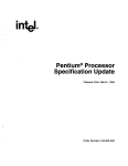
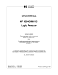
Figure 1-1. Preprocessor Interface Assembly
Setting Up the HP E2443B
1-6
HP E2443B
Pentium CPU Preprocessor Interface
Connecting to
the Target
System
Caution
The following steps explain how to connect the HP E2443B
Preprocessor Interface to your target system:
To prevent equipment damage, be sure to remove power from the
target system whenever the preprocessor interface or microprocessor is
being connected or disconnected.
1. Remove the Pentium microprocessor from its socket on the
target system and store it in a protected environment.
Caution
Serious damage to the target system or preprocessor interface can
result from incorrect connection. Note the position of pin A1 (figure
1-1) on the preprocessor interface connector and the target system
socket prior to inserting the connector in the socket. Also, take care to
align the preprocessor interface connector with the socket on the target
system so that all microprocessor pins are making contact.
2. Plug the preprocessor interface connector into the
microprocessor socket on the target system.
Note
If the preprocessor interface connector interferes with components of
the target system or if a higher profile is required, additional plastic pin
guards can be added. Plastic pin guards can be ordered from
Hewlett-Packard using the part number 1200-1753. However, any
273-pin PGA IC socket with a Pentium CPU footprint and gold-plated
pins can be used.
3. Plug the Pentium microprocessor into the socket of the
preprocessor interface board. The socket on the preprocessor
interface board is designed with low-insertion-force pins to allow
you to install or remove the microprocessor with a minimum
amount of force.
HP E2443B
Pentium CPU Preprocessor Interface
Setting Up the HP E2443B
1-7
Caution
Care must be used when removing a microprocessor or socket from the
preprocessor interface board to prevent damaging the traces on the
board.
4. If you want to fully capture the execution trace, disable the cache
memory. If you leave the cache enabled, all data will still be
captured and decoded but you may lose unexecuted-prefetch
flagging or synchronization with the execution trace. To capture
four-cycle burst transfers you must leave the cache enabled. This
will allow you to view all data coming across the bus, although
some of the execution trace information will be lost.
The cache can be disabled with software by setting CR0.CD,
TR12.CI, or the PCD bits in the page table entries to "1". It can
be disabled in hardware by deasserting KEN# .
Note
If the execution tracing enable bit (bit 1) in TR12.C1 is set to 1, the
branch trace message cycles will be captured and decoded by the logic
analyzer. This will allow the trace to indicate that branches have
occurred, even with the cache enabled.
5. If possible, you may want to disable page translation so that the
physical addresses that the preprocessor interface monitors are
effectively the logical addresses. Page translation can be disabled
by setting CR0.PG to zero.
Setting Up the HP E2443B
1-8
HP E2443B
Pentium CPU Preprocessor Interface
Connecting to
the HP E2443B
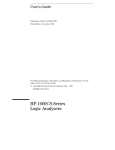
Connect the logic analyzer probes to the cable connectors of the
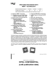
preprocessor interface board as listed in table 1-3. Figure 1-2 shows
the relative locations of the logic analyzer cards.
Figure 1-2. Logic Analyzer Card Locations
(relative locations, actual slots used can vary)
Power Up /
Down Sequence
When powering up, the logic analyzer must be powered up first, and
then the target system. The logic analyzer provides the power to the
active circuits on the preprocessor interface; unpowered circuits may
cause improper operation of the target system.
When powering down, power down the target system first, and then the
logic analyzer.
HP E2443B
Pentium CPU Preprocessor Interface
Setting Up the HP E2443B
1-9
Table 1-3. Connections and Configuration Files
HP 1660A
Logic Analyzer
Pod
HP E2443B
HP 16540/16541A,D
Logic Analyzer
Pod *
HP 16550A
Logic Analyzer
Pod **
Master Card, Pod 1
Master Card, Pod 3
Pod 1
P1 (STAT) Clk1
Exp. Card 3, Pod 3
Master Card, Pod 4
Pod 2
P2 (STAT)
Exp. Card 3, Pod 1
Master Card, Pod 5
Pod 3
P3 (ADDR)
Exp. Card 3, Pod 2
Master Card, Pod 6
Pod 4
P4 (ADDR)
Exp. Card 2, Pod 1
Expander Card, Pod 1
Pod 5
P5 (DATA)
Exp. Card 2, Pod 2
Expander Card, Pod 2
Pod 6
P6 (DATA)
Exp. Card 1, Pod 1
Expander Card, Pod 3
Pod 7
P7 (DATA_B)
Exp. Card 1, Pod 2
Expander Card, Pod 4
Pod 8
P8 (DATA_B)
Exp. Card 2, Pod 3
Expander Card, Pod 5
--
P9 (additional status)
Exp. Card 1, Pod 3
Expander Card, Pod 6
--
P10 (additional status)
(Into)
Connector
Configuration Files
CPENT_1
*
CPENT_2
CPENT_3
For the HP 16541A,D cards, expansion card 1 is the physically highest HP 16541A,D card, expansion card 2 is the
second physically highest HP 16541A,D card, and expansion card 3 is the third highest HP 16541A,D card (see fig. 1-2).
** For the HP 16550A cards, the Master Card is the lower card, and the expansion card is the higher card. Note that the
two HP 16550A cards must be configured as a single logic analyzer.
Setting Up the HP E2443B
1-10
HP E2443B
Pentium CPU Preprocessor Interface
Setting Up the
Analyzer from
the Disk
The logic analyzer can be configured for Pentium CPU analysis by
loading the appropriate configuration file. Loading this file will also
load a default inverse assembler file (IAPENT or IAPENTE). To load
the configuration and inverse assembler:
1. Install the flexible disk in the front disk drive of the logic
analyzer. (The HP 16500B mainframe has a hard disk drive. You
can create a directory on the hard drive and copy the files from
the flexible disk into the directory. For step two, select "Hard
Disk.")
2. Select the System Front Disk menu.
3. Configure the menu to "Load" the analyzer configuration from
disk.
4. Select the appropriate module (such as "100/500 MHz LA" or
"Analyzer") for the load.
5. Use the knob to select the appropriate configuration file (see
table 1-3).
6. Execute the load operation to load the file into the logic analyzer.
There are three inverse assemblers in the HP E2443B software. Table
1-4 shows the default inverse assembler which is automatically loaded
by the configuration files. It also shows the different logic analyzer
configurations which are supported by each inverse assembler. Pages
2-14 and 2-18 contain additional information on the different inverse
assemblers.
To load a different inverse assembler after the configuration file has
been loaded, repeat steps 1 - 6 above, except that for step 5, select the
desired inverse assembler.
HP E2443B
Pentium CPU Preprocessor Interface
Setting Up the HP E2443B
1-11
Table 2-4. Inverse Assembler Compatibility
Logic Analyzer /
Mainframe
IAPENT
IAPENTE
IAPENTD
HP 16500A
Mainframe
default
no
yes
HP 16500B
Mainframe
yes *
default
yes
HP 1660A
Logic Analyzer,
software V01.xx
default
no
yes
HP 1660A
Logic Analyzer,
software V02.00
or higher
yes *
default
yes
* Although this inverse assembler supports these logic analyzers, it does not provide all
the features available with IAPENTE.
Timing Analysis
The configuration loaded for state analysis may also be used for timing
analysis. In Timing mode, the signals are buffered by a 74FCT646AT,
with a maximum buffer delay of 6.3 ns (minimum 2.0 ns), and a typical
1.0 ns skew. To configure the logic analyzer for timing analysis:
1. Set the switches for timing (see page 1-3).
2. Load the appropriate configuration file from the disk.
3. Select the Configuration menu of the logic analyzer.
4. Select the Type field and select Timing.
Setting Up the HP E2443B
1-12
HP E2443B
Pentium CPU Preprocessor Interface
Analyzing the Intel Pentium CPU
2
Introduction
This chapter provides reference information on the format
specification and symbols configured by the HP E2443B software. It
also provides information about the inverse assemblers and status
encoding.
Format
Specification
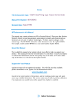
When you use the HP E2443B Preprocessor Interface, the format
specification set up by the software will look similar to that shown in
figure 2-1. There are some slight differences in the displays, according
to which logic analyzer you are using. Table 3-1 in chapter 3 lists the
Pentium CPU signals for the HP E2443B Preprocessor Interface and
their corresponding lines to the logic analyzer.
Note
The Setup/Hold time must remain in the current setting (4 ns setup/0 s
hold for the HP 16540/16541A,D, 3.5 ns setup/0 s hold for the
HP 1660A and HP 16550A) for proper operation with the HP E2443B.
Figure 2-1. Format Specification
HP E2443B
Pentium CPU Preprocessor Interface
Analyzing the Intel Pentium CPU
2-1
Symbols
The configuration files set up symbol tables in the logic analyzer. The
tables contain alphanumeric values which identify data patterns or
ranges.
Table 2-1 lists the bits in the STAT label. Table 2-2 lists the additional
status bits which are available on pods 9 and 10. Table 2-3 lists the
additional status bits which are available on the HP 1660A and
HP 16550A Logic Analyzers. Table 2-4 lists the signals which are
available on the 2 x 4 header. Table 2-5 lists the symbols for the Cycle
label. Table 2-6 lists the symbols for the Excptn label, and table 2-7
lists the symbols for the Xfer label. Table 2-8 lists the symbols for
BE# . There are also symbols for many of the status signals (listed
below table 2-8). The patterns for each symbol listed in the tables are
shown in the binary base. In the actual software, these patterns may be
listed in the hexadecimal base to conserve display space.
Table 2-1. STAT Label Bits
Pod / Bit
Status Signals
P1 / 7 - 0
BE7 - BE0
Byte Enable signals for the data bus.
P1 / 8
IBT
A high indicates a branch was taken.
P1 / 9
KEN#
P1 / 10
CACHE#
P1 / 11
W/R#
A low indicates read and a high indicates write.
P1 / 12
D/C#
A low indicates a code/special cycle and a high indicates a
data cycle.
P1 / 13
M/IO#
A low indicates an I/O cycle and a high indicates a memory
cycle.
P1 / 14
LOCK#
A low indicates that the current bus cycle is locked.
P1 / 15
A20M#
A low indicates an Address-bit 20 mask for internal cache
lookups or memory cycles.
Analyzing the Intel Pentium CPU
2-2
Description
A low on this signal indicates that the current cycle is
cacheable, and will therefore be a burst.
A low on this signal indicates internal cacheability of the
cycle (for reads) or a burst writeback cycle (for writes).
HP E2443B
Pentium CPU Preprocessor Interface
Table 2-1. STAT Label Bits (continued)
Pod / Bit
Status Signals
Description
P2 / 0
Valid
This signal is generated by the preprocessor interface. A
high indicates that a data transfer is valid.
P2 / 1
ADS#
A low indicates that a new valid bus cycle is being driven by
the Pentium CPU.
P2 / 2
NA#
A low indicates that the external memory is ready to accept
a new bus cycle, although all data transfers for the current
cycle are not completed.
P2 / 3
BRDY#
P2 / 4
BRDYC#
P2 / 5
PRDY
P2 / 6
AHOLD
A high indicates an address hold request.
P2 / 7
EADS#
A low indicates a valid external address has been driven
onto the Pentium CPU address pins to be used for an
inquiry cycle.
P2 / 8
HIT#
This signal indicates the outcome of the most recent
inquire cycle.
P2 / 9
HITM#
A low indicates (during inquire cycles) that a hit to a
modified line in the data cache has occurred.
P2 / 13 - 10
BT3 - BT0
P2 / 14
BOFF#
A low indicates that the Pentium CPU should abort all
outstanding bus cycles and float its bus on the next cycle.
P2 / 15
HLDA
A high indicates that the Pentium CPU has acknowledged
a hold request, and given up the bus.
A low indicates valid data on the data pins.
A low indicates valid data on the data pins for cacheable
data.
A high indicates that the Pentium CPU is ready to accept a
Probe Mode instruction.
Branch target address bits.
HP E2443B
Pentium CPU Preprocessor Interface
Analyzing the Intel Pentium CPU
2-3
Table 2-2. Additional Status Bits
Pod / Bit
Status Signals
Description
P9 / 0
R/S#
A low indicates that the normal execution of the CPU has
been stopped and placed into an idle state, possibly for
execution of Boundary Scan/Probe Mode instructions.
P9 / 1
ADSC#
Address strobe used in chip-set mode.
P9 / 2
HOLD
A high indicates a system bus hold request.
P9 / 3
BREQ
A high indicates that the Pentium CPU has internally
generated a bus request.
P9 / 4
INTR
A high indicates an external interrupt.
P9 / 5
NMI
A high indicates a non-maskable external interrupt.
P9 / 6
SCYC
P9 / 7
BUSCHK#
P9 / 8
FLUSH#
P9 / 9
INV
P9 / 10
EWBE#
A high (inactive) indicates that a write through cycle is
pending in the external system.
P9 / 11
WB/WT#
A low indicates that the current cache line is write-through,
and a high indicates write-back.
P9 / 12
PWT
Indicates cache writeback on a page-by-page basis.
P9 / 13
PCD
Indicates cacheability on a page-by-page basis.
P9 / 14
RESET
P9 / 15
INIT
Analyzing the Intel Pentium CPU
2-4
A high indicates a split cycle (more than two cycles will be
locked together).
A low indicates that the system has unsuccessfully
completed a bus cycle.
A low indicates that the Pentium CPU will writeback all
modified lines and invalidate its cache.
Indicates the final cache line state for an inquire cycle hit.
A high indicates that the Pentium CPU will begin
execution from a known reset state.
A high indicates that the Pentium CPU will begin
execution from a known reset state, except the internal
caches and some register values are left unchanged.
HP E2443B
Pentium CPU Preprocessor Interface
Table 2-2. Additional Status Bits (continued)
Pod / Bit
Status Signals
Description
P10 / 7 - 0
DP7 - 0
P10 / 8
IU
A high indicates that an instruction in the u-pipeline has
complete execution.
P10 / 9
IV
A high indicates that an instruction in the v-pipeline has
complete execution.
P10 / 10
SMI#
A low indicates a System Power Management interrupt.
P10 / 11
SMIACT#
A low indicates that the Pentium CPU is operating in
System Management mode.
P10 / 12
PM0/BP0
P10 / 13
PM1/BP1
P10 / 14
BP2
BP are the breakpoint pins that indicate a breakpoint
match with the debug registers DR3 - 0 when they are
programmed as such; the PM are the performance
monitoring pins.
P10 / 15
BP3
Data parity pins.
HP E2443B
Pentium CPU Preprocessor Interface
Analyzing the Intel Pentium CPU
2-5
Table 2-3. Additional Status Bits (HP 1660A and HP 16550A only)
Pod / Bit
Signals
Description
P3 / Clk1
FERR#
A low indicates that an unmasked floating point error has
occurred.
P4 / Clk1
IERR#
A low indicates either an internal parity error or a
functional redundancy error.
P5 / Clk1
IGNNE#
P6 / Clk1
PEN#
This signal partially determines whether a machine check
exception will be taken as a result of a parity error on a
read cycle.
P7 / Clk1
PCHK#
This signal indicates the result of a parity check on a read
cycle.
P8 / Clk1
AP
P9 / Clk1
* APCHK#
A low indicates a parity error on the address bus.
P10 / Clk1
* FRCMC#
A low indicates that the Pentium CPU has been
configured in checker mode, while a high indicates that
the Pentium CPU has been configured in master mode.
*
A low partially indicates that the Pentium CPU will
ignore any pending unmasked numeric exception and
continue executing floating point instructions for the
entire duration that the signal is asserted.
Address Parity for the address bus.
These signals are not available on the HP 1660A Logic Analyzer.
Note
These signals are only available on the HP 1660A and HP 16550A
Logic Analyzers. Each signal has its own label in the display.
Analyzing the Intel Pentium CPU
2-6
HP E2443B
Pentium CPU Preprocessor Interface
Table 2-4. 2 x 4 Header Pins (JTAG)
Signals *
*
Description
TCK
Test logic clock signal.
TDI
Test logic serial input.
TDO
Test logic serial output.
TMS
Test logic control signal.
TRST
Test logic reset signal.
These signals are located on the 2 x 4 header (see figure 1-1).
HP E2443B
Pentium CPU Preprocessor Interface
Analyzing the Intel Pentium CPU
2-7
The Cycle symbols consist of the following signals, in the designated
groupings:
(HLDA BOFF# ) (LOCK# M/IO# D/C# W/R# ) (BE7-4# ) (BE3-0# )
Table 2-5. Cycle Symbols
Symbol
Pattern
HLDA & BOFF
Hold Ack
Bus Backoff
Int Ack 1st
Int Ack 2nd
1
1
0
0
0
0
1
0
1
1
x
x
x
x
x
x
x
x
0
0
x
x
x
0
0
x
x
x
0
0
x
x
x
1
1
x
x
x
1
1
x
x
x
1
1
x
x
x
0
1
x
x
x
1
1
x
x
x
1
1
x
x
x
1
1
x
x
x
1
0
I/O Read
I/O Write
Lckd Read
Lckd Write
Code Read
Lckd Code Rd
0
0
0
0
0
0
1
1
1
1
1
1
1
1
0
0
1
0
0
0
0
0
1
1
1
1
1
1
0
0
0
1
0
1
0
0
x
x
x
x
x
x
x
x
x
x
x
x
x
x
x
x
x
x
x
x
x
x
x
x
x
x
x
x
x
x
x
x
x
x
x
x
x
x
x
x
x
x
x
x
x
x
x
x
Reserved
Mem Read
Mem Write
Lckd Mem Rd
Lckd Mem Wr
0
0
0
0
0
1
1
1
1
1
x
1
1
0
0
1
1
1
1
1
0
1
1
1
1
1
0
1
0
1
x
x
x
x
x
x
x
x
x
x
x
x
x
x
x
x
x
x
x
x
x
x
x
x
x
x
x
x
x
x
x
x
x
x
x
x
x
x
x
x
Shutdown
Flush
Halt
Writeback
Flush Ack
Brch Trg Msg
Undf Special
---
0
0
0
0
0
0
0
x
1
1
1
1
1
1
1
x
x
x
x
x
x
x
x
x
0
0
0
0
0
0
0
x
0
0
0
0
0
0
0
x
1
1
1
1
1
1
1
x
x
x
x
x
x
x
x
x
x
x
x
x
x
x
x
x
x
x
x
x
x
0
x
x
x
x
x
x
0
x
x
x
x
x
x
0
x
x
x
x
x
x
0
x
x
x
x
x
x
0
x
x
x
x
x
x
0
x
x
x
x
x
x
x
Analyzing the Intel Pentium CPU
2-8
HP E2443B
Pentium CPU Preprocessor Interface
The Excptn symbols consist of the following signals, in the designated
groupings:
(HLDA BOFF# ) (D7-0) (M/IO# D/C# W/R# ) (BE7-0# )
Table 2-6. Excptn Symbols
Symbol
Pattern
Int Ack 1st Cycl
0 1
x x x x x x x x
0 0 0
1 1 1 0 1 1 1 1
0:Divide Error
1:Debug Excptn
2:NMI Interrupt
3:Breakpoint
0
0
0
0
1
1
1
1
0
0
0
0
0
0
0
0
0
0
0
0
0
0
0
0
0
0
0
0
0
0
0
0
0
0
1
1
0
1
0
1
0
0
0
0
0
0
0
0
0
0
0
0
1
1
1
1
1
1
1
1
1
1
1
1
1
1
1
1
1
1
1
1
1
1
1
1
1
1
1
1
0
0
0
0
4:INTO Overflow
5:BOUND Rng Exc
6:Invalid Opcode
7:Dev Not Avail
0
0
0
0
1
1
1
1
0
0
0
0
0
0
0
0
0
0
0
0
0
0
0
0
0
0
0
0
1
1
1
1
0
0
1
1
0
1
0
1
0
0
0
0
0
0
0
0
0
0
0
0
1
1
1
1
1
1
1
1
1
1
1
1
1
1
1
1
1
1
1
1
1
1
1
1
1
1
1
1
0
0
0
0
8:Double Fault
10:Inv Task SSeg
11:Seg N/Present
12:Stack Fault
0
0
0
0
1
1
1
1
0
0
0
0
0
0
0
0
0
0
0
0
0
0
0
0
1
1
1
1
0
0
0
1
0
1
1
0
0
0
1
0
0
0
0
0
0
0
0
0
0
0
0
0
1
1
1
1
1
1
1
1
1
1
1
1
1
1
1
1
1
1
1
1
1
1
1
1
1
1
1
1
0
0
0
0
13:Gen Protectn
14:Page Fault
16:Flt Point Err
17:Alignment Chk
---
0
0
0
0
x
1
1
1
1
x
0
0
0
0
x
0
0
0
0
x
0
0
0
0
x
0
0
1
1
x
1
1
0
0
x
1
1
0
0
x
0
1
0
0
x
1
0
0
1
x
0
0
0
0
x
0
0
0
0
x
0
0
0
0
x
1
1
1
1
x
1
1
1
1
x
1
1
1
1
x
1
1
1
1
x
1
1
1
1
x
1
1
1
1
x
1
1
1
1
x
0
0
0
0
x
HP E2443B
Pentium CPU Preprocessor Interface
Analyzing the Intel Pentium CPU
2-9
The Xfer symbols consist of the following signals:
HLDA BOFF#
W/R#
CACHE#
KEN#
Table 2-7. Xfer Symbols
Symbol
1 Xfer Rd
1 Xfer Rd
4 Xfer Rd
1 Xfer Wr
4 Xfer Wr
---
Analyzing the Intel Pentium CPU
2-10
Pattern
0
0
0
0
0
x
1
1
1
1
1
x
0
0
0
1
1
x
1
x
0
1
0
x
x
1
0
x
x
x
HP E2443B
Pentium CPU Preprocessor Interface
Table 2-6. BE# Symbols
Symbol
Additional
Symbols
Pattern
64/b7:0
0 0 0 0
0 0 0 0
32/b3:0
32/b4:1
32/b5:2
32/b6:3
32/b7:4
1
1
1
1
0
1
1
1
0
0
1
1
0
0
0
1
0
0
0
0
0
0
0
0
1
0
0
0
1
1
0
0
1
1
1
0
1
1
1
1
16/b1:0
16/b2:1
16/b3:2
16/b4:3
16/b5:4
16/b6:5
16/b7:6
1
1
1
1
1
1
0
1
1
1
1
1
0
0
1
1
1
1
0
0
1
1
1
1
0
0
1
1
1
1
0
0
1
1
1
1
0
0
1
1
1
1
0
0
1
1
1
1
1
0
1
1
1
1
1
1
8/b0
8/b1
8/b2
8/b3
8/b4
8/b5
8/b6
8/b7
1
1
1
1
1
1
1
0
1
1
1
1
1
1
0
1
1
1
1
1
1
0
1
1
1
1
1
1
0
1
1
1
1
1
1
0
1
1
1
1
1
1
0
1
1
1
1
1
1
0
1
1
1
1
1
1
0
1
1
1
1
1
1
1
None
---
1 1 1 1
x x x x
1 1 1 1
x x x x
There are also symbols for the following signals: KEN# , CACHE# ,
W/R# , D/C# , M/IO# , LOCK# , SCYC, IBT, IV, IU, WB/WT# ,
PWT, PCD, BUSCK# , FLUSH# , IERR# , INTR, NMI, SMI# ,
SMIAC# , A20M# , AP, APCHK# , ADS# , AHOLD, BOFF# ,
BRDY# , BRDYC# , EADS# , EWBE# , HIT# , HITM# , HLDA,
HOLD, INV, NA# , BREQ, RESET, INIT, PEN# , PCHK# , FERR# ,
IGNNE# , PRDY, and R/S# .
HP E2443B
Pentium CPU Preprocessor Interface
Analyzing the Intel Pentium CPU
2-11
Listing Menu
Captured data is displayed as shown in figure 2-2 (with the IAPENT
inverse assembler) or figure 2-3 (with the IAPENTE inverse
assembler). The inverse assemblers are constructed so the mnemonic
output closely resembles the actual assembly source code. In figure
2-3, the unexecuted prefetches have been suppressed.
The logic analyzers always probe the full 64-bit data bus of the Pentium
CPU. When fewer than the full 64 bits of the data bus are used by a
memory cycle, the inverse assembler marks the bytes not used by the
microprocessor with "xx."
Figure 2-2. State Listing, IAPENT Inverse Assembler
Analyzing the Intel Pentium CPU
2-12
HP E2443B
Pentium CPU Preprocessor Interface
Figure 2-3. State Listing, IAPENTE Inverse Assembler
(Unexecuted Prefetches Suppressed)
Burst and
Cacheable Data
The logic analyzer can track burst (4-transfer) and non-burst
(1-transfer) cycles. During burst transfers the microprocessor holds
the address constant during the entire burst. The inverse assembler
listing displays the two least significant hexadecimal digits of the actual
address (derived by the inverse assembler) at the left side of the
column.
Up to eight instructions may be displayed for a single analyzer state,
because the Pentium CPU fetches eight instruction bytes from program
memory. If the first byte of these eight bytes contains a single-byte
instruction, the next sequential instruction begins in the next higher
byte. This process continues from the least significant byte to the most
significant byte until all of the fetched bytes are used. When a single
state contains more than one instruction, each instruction is displayed
on a separate line.
HP E2443B
Pentium CPU Preprocessor Interface
Analyzing the Intel Pentium CPU
2-13
The Pentium
CPU Inverse
Assemblers
The HP E2443B Preprocessor Interface software contains three
inverse assemblers. There are two default inverse assemblers,
IAPENT and IAPENTE, and a data-mode inverse assembler,
IAPENTD. IAPENTE contains additional features which use the
increased capabilities of some of the logic analyzers (only available
with the HP 16500B mainframe, and the HP 1660A Logic Analyzer
with software version V02.00 or higher). For more information on the
IAPENTE features, see "The IAPENTE Inverse Assembler" in this
chapter.
The default inverse assemblers analyze the microprocessor code and
disassemble it into Pentium CPU mnemonics, which are displayed on
the logic analyzer screen. Unexecuted prefetches are marked with a
hyphen (-).
The data-mode inverse assembler (IAPENTD) functions like the
default inverse assemblers, except that it does not decode instructions
or mark unused prefetches. IAPENTD is useful for examining data
flow, while IAPENT or IAPENTE are useful for examining instruction
flow. You can also store data, and re-examine it later using a different
inverse assembler.
The inverse assemblers only work in State-Per-Transfer and Debugger
modes. They do not work in State-Per-Clock or Timing modes.
Address Labels
Two different address labels are provided, ADDR and ADDR_.
ADDR provides the full 32 address bits (A31:0), while ADDR_
provides the upper 24 address bits (A31:8).
When using the inverse assembler, use ADDR_ in the listing. ADDR_
gives you the upper 24 bits of the address, while the inverse assembler
display gives you the lower eight address bits (A7:0) in its first two
columns. Using these two fields together gives you the entire 32
address bits.
The ADDR label displays the actual (acquired) 32-bit address, with
A2:0 = 000 binary. When the inverse assembler is turned off, the
ADDR field can be used to display the full address in hexadecimal
format.
Analyzing the Intel Pentium CPU
2-14
HP E2443B
Pentium CPU Preprocessor Interface
Prefetched
Instructions
The Pentium CPU microprocessor is a prefetching microprocessor. It
may prefetch up to 64 bytes (eight 64-bit code fetches) before the
current opcode. When a program executes an instruction that causes a
branch, the prefetched code is not used and will be discarded by the
microprocessor. The inverse assembler marks unused prefetches with
a hyphen "–" in the third column of the display.
The logic analyzer captures prefetches, even if they are not executed.
Therefore, care must be taken when you are specifying a trigger
condition or a storage qualification and the instruction of interest
follows an instruction that may cause branching. An unused prefetch
may generate an unwanted trigger.
The Pentium CPU has a prefetch queue of essentially 64 bytes. This
means that by the time a branching instruction is fully decoded, up to
64 other instruction bytes may have already been prefetched across the
data bus, and stored in the logic analyzer. Both exceptions and
instructions can cause the prefetch queue to be flushed and
subsequently refilled. Branches, jumps, calls, returns, and system
control instructions are the most common causes of prefetch queue
flushes, but there are many others. Refer to your Pentium CPU user’s
manual for more information.
HP E2443B
Pentium CPU Preprocessor Interface
Analyzing the Intel Pentium CPU
2-15
Synchronizing the
Inverse Assembler
In some cases the prefetch marking algorithm in the inverse assembler
may lose synchronization, and unused prefetches or executed
instructions may be incorrectly marked. If you suspect that the inverse
assembler has lost synchronization, re-synchronize the inverse
assembler by pointing to an executed instruction. Once synchronized,
the inverse assembler will disassemble from this state through the end
of the screen. To point to an executed instruction:
1. Select a line on the display that you know contains the first byte
of an executed instruction.
2. Roll this line to the top of the listing.
Note
The cursor location is not the top of the listing. In figure 2-2, the
instruction DA HLT is the top of the listing.
3. For the IAPENT or IAPENTD inverse assemblers, select the
"Invasm" field at the top of the display. A pop-up appears with
the following choices:
Size 16 Byte 0/8
Size 16 Byte 1/9
Size 16 Byte 2/A
Size 16 Byte 3/B
Size 16 Byte 4/C
Size 16 Byte 5/D
Size 16 Byte 6/E
Size 16 Byte 7/F
Size 32 Byte 0/8
Size 32 Byte 1/9
Size 32 Byte 2/A
Size 32 Byte 3/B
Size 32 Byte 4/C
Size 32 Byte 5/D
Size 32 Byte 6/E
Size 32 Byte 7/F
For the IAPENTE inverse assembler, select the "Invasm Options"
button, and use the "Code Synchronization" portion of the
submenu.
Size, as used here, refers to the default operand size for this code
(16 or 32 bits).
4. Select the choice that identifies which byte of the captured state
contains the first byte of the code fetch and what the default
operand size is for this code (16 or 32 bits). With the IAPENTE
inverse assembler, also select "Align".
Analyzing the Intel Pentium CPU
2-16
HP E2443B
Pentium CPU Preprocessor Interface
Rolling the screen up will inverse assemble the lines as they appear on
the bottom of the screen. If you jump to another area of the acquisition
buffer by entering a new line number, you may have to re-synchronize
the inverse assembler by repeating steps 1 through 4.
Operand Size
Byte Enable
Validity
Incomplete
Decoding
Opcode Data
Numeric Bases
Branch Trace
Messaging
Illegal Instructions
Note
The "= " symbol is displayed in the fourth column of the inverse
assembly display for 32-bit operands. The "= " symbol will appear for
default 32-bit operand operations, as well as for operations when the
operand size prefix is encountered and decoded.
The Byte Enables are not valid during cache accesses (bursts). Since
all cache reads and writes must be 64 bits, all data lines are valid during
these cycles.
If a complete opcode is not present, the inverse assembler will not be
able to decode it. A pair of asterisks "**" will be listed on the display.
Most data is displayed in hexadecimal format. An exceptions is the
operand for the INT value, which is displayed in decimal. Decimal
numbers are indicated by a "d" suffix.
The Pentium CPU inverse assemblers decode branch trace messages,
which gives you branch target addresses. This is especially useful for
tracing execution while operating out of cache.
When the inverse assembler decodes an illegal instruction, the message
"Illegal Opcode" is displayed, along with the byte(s) which caused the
decoded illegal opcode. This message is often an indication that the
inverse assembler has lost synchronization (see page 2-16).
Do not modify the ADDR, DATA, DATA_B, or STAT labels in the
format specification if you want inverse assembly. Changes may cause
incorrect results. Also note that if the trace specification is modified to
store only selected bus cycles, incorrect or incomplete inverse assembly
may result.
HP E2443B
Pentium CPU Preprocessor Interface
Analyzing the Intel Pentium CPU
2-17
The IAPENTE
Inverse
Assembler
The IAPENTE inverse assembler contains additional features which
use the increased capabilities of some of the logic analyzers. It
supports the HP 16540/16541A,D and HP 16550A Logic Analyzers in
the HP 16500B mainframe, and the HP 1660A Logic Analyzer with
software version V02.00 or higher. For those logic analyzer systems,
the IAPENTE inverse assembler is automatically loaded when the
appropriate configuration file is loaded. Note that all the features in
the IAPENT inverse assembler are also included in the IAPENTE
inverse assembler (see previous section).
The IAPENTE Inverse Assembly Options menu contains three
functions: display filtering with Show/Suppress selections, Code
Synchronization, and IDT description entry (see figure 2-4). The
following sections describe these functions.
Note
If the X or O pattern markers are turned on, and the designated
pattern is found in a state that has been Suppressed with display
filtering, the following message will appear on the logic analyzer
display: "X (or O) pattern found, but state is suppressed."
Figure 2-4. IAPENTE Inverse Assembly Options
Analyzing the Intel Pentium CPU
2-18
HP E2443B
Pentium CPU Preprocessor Interface
Show/Suppress
The Suppress/Show settings determine whether the various
microprocessor operations are shown or suppressed on the logic
analyzer display. Figure 2-4 shows the microprocessor operations
which have this option. The settings for the various operations do not
affect the data which is stored by the logic analyzer, they only affect
whether that data is displayed or not. The same data can be examined
with different settings, for different analysis requirements.
This function allows faster analysis in two ways. First, unneeded
information can be filtered out of the display. Figure 2-4 shows the
settings to suppress unexecuted prefetches. Figure 2-3 (page 2-13)
shows a listing with the unexecuted prefetches suppressed, so that only
executed instructions are displayed. A comparison of figures 2-2 and
2-3 shows the difference in the listing display.
Second, particular operations can be isolated by suppressing all other
operations. For example, I/O accesses can be shown, with all other
operations suppressed, allowing quick analysis of I/O accesses.
Code
Synchronization
The Code Synchronization enables the inverse assembler to
resynchronize with the microprocessor code. In some cases the
prefetch marking algorithm in the inverse assembler may lose
synchronization, and unused prefetches or executed instructions may
be incorrectly marked. If any of the Code Reads are suppressed, this
could cause some executed instructions to be missing from the display.
To resynchronize the inverse assembler, use the procedure on page
2-16.
IDT Description
The IDT Description settings include Mode, IDT Start, and IDT Size.
Mode can be Protected, Real, or Virtual. IDT Start refers to the
starting address of the Interrupt Descriptor Table, and IDT Size refers
to the size of the table. Set these functions to match the target system
settings.
In most cases, the inverse assembler can automatically determine the
target system settings, and will operate properly regardless of the
settings entered. The inverse assembler uses the information from
these settings only in cases of uncertainty. If you suspect that the
inverse assembler is disassembling improperly, check that these settings
match your target system.
HP E2443B
Pentium CPU Preprocessor Interface
Analyzing the Intel Pentium CPU
2-19
Modes of
Operation
The HP E2443B can capture Pentium CPU data in four modes;
Timing, State-Per-Clock, State-Per-Transfer, and Debugger. In Timing
mode, the signals are buffered, but otherwise passed straight through
to the logic analyzer; in State-Per-Clock mode, all signals are latched
by CLK, and clocked into the logic analyzer each CLK cycle. This
allows the logic analyzer to capture wait states and idle states, in
addition to valid data states. In State-Per-Transfer and Debugger
modes, address pipelining is realigned, and only valid data transfers are
clocked into the logic analyzer. Debugger mode is identical to
State-Per-Transfer mode with the exception that, whenever IU, IV or
IBT are asserted, data is captured regardless of whether or not it is
valid.
Timing mode also allows a choice of buffered or phase-locked loop
clocks (see Chapter 1). Chapter 1 shows the switch settings for
selecting the different modes of operation.
Qualified /
Non-qualified
Clocking
In non-qualified clocking, Clk1 (on the HP E2443B pod P1) is used
to clock information into the logic analyzer. In qualified clocking, only
those edges of Clk1 that occur when ClkQual is asserted will clock
information into the logic analyzer. Therefore, qualified clocking
allows you to filter information, since ClkQual must be asserted before
the logic analyzer is clocked by Clk1 .
The logic analyzer must use qualified clocking for State-Per-Transfer
and Debugger modes; it can be clocked as qualified or non-qualified
for State-Per-Clock mode. With non-qualified clocking, every state is
captured, regardless of the settings for the switches. The configuration
file sets up the logic analyzer for qualified clocking.
To change to non-qualified clocking, use the Format menu to remove
the clock qualifier. The clock qualifier is the M Clock on the
HP 16550A, and the K Clock on the HP 16540/16541A,D and
HP 1660A Logic Analyzers. Figure 2-5 shows the Format specification
with the clock qualifier removed. Only the L Clock (Clk1) is shown in
the Master Clock field. Clk1 is the L clock in the HP 16550A ; it is the
J clock in the HP 1660A and HP 16540/16541A,D.
Analyzing the Intel Pentium CPU
2-20
HP E2443B
Pentium CPU Preprocessor Interface
ClkQual
In State-Per-Clock mode, six signals can be used as inputs to the clock
qualifier (see Chapter 1). The inputs are selected by closing the
appropriate switches. The only states which will be captured are those
in which the signal for a selected (closed) switch is asserted. The
equation for the clock qualifier in State-Per-Clock mode is:
ClkQual =
(St-Pr-Clk)
![(BRDYsel & !BRDY# ) or (BRDYCsel & !BRDYC# )
or (ADSsel & !ADS# ) or (EADSsel & !EADS# )
or (HLDAsel & HLDA) or (BOFFsel & !BOFF# )]
In State-Per-Transfer and Debugger modes, the preprocessorgenerated signal "Valid" is part of ClkQual. One additional signal
(EADS# ) can be used as an input to the clock qualifier, by closing the
switch. In addition, in Debugger mode data is captured whenever IU,
IV, or IBT are asserted.
Whenever BOFF# or HLDA is asserted, the preprocessor interface
automatically switches to State-Per-Clock mode, and the
State-Per-Clock ClkQual becomes relevant. There are five additional
signals which can be used in the State-Per-Clock ClkQual. If none of
the switches are closed, no information will be clocked into the logic
analyzer as long as BOFF# or HLDA is asserted. This allows
maximum flexibility of logic analyzer storage and filtering when the
Pentium CPU is tri-stated.
Note that information is not inverse assembled while the preprocessor
interface is in State-Per-Clock mode. When BOFF# or HLDA is
deasserted, the preprocessor interface switches back to
State-Per-Transfer or Debugger mode.
The equations for the State-Per-Transfer and Debugger clock
qualifiers are:
Valid =
![!(BRDY# & BRDYC# ) & (Pentium CPU in T2, T12, T2P states)]
ClkQual (St-Pr-Tr) =
![(Valid) or (EADSsel & !EADS# )]
ClkQual (Debugger) = ![(Valid) or (EADSsel & !EADS# ) or IU or IV or IBT]
HP E2443B
Pentium CPU Preprocessor Interface
Analyzing the Intel Pentium CPU
2-21
Figure 2-5. Clock Qualifier Removed From Master Clock
Analyzing the Intel Pentium CPU
2-22
HP E2443B
Pentium CPU Preprocessor Interface
State
Waveforms
Using
State-Per-Clock
Mode
The State-Per-Clock mode can be used with the State Waveforms
function of the logic analyzer to produce state timing diagrams. The
horizontal axis displays state transitions rather than absolute time.
Figure 2-6. State Waveforms
HP E2443B
Pentium CPU Preprocessor Interface
Analyzing the Intel Pentium CPU
2-23
3
General Information
Introduction
This chapter contains additional reference information including the
characteristics and signal mapping for the HP E2443B Preprocessor
Interface.
Characteristics
The following operating characteristics are not specifications, but are
typical operating characteristics for the HP E2443B Preprocessor
Interface. These characteristics are included as additional information
for the user.
Microprocessor
Compatibility:
Microprocessor Package:
Accessories Required:
Maximum Clock Speed:
Target Signal Timing:
Intel Pentium CPU.
273-pin PGA.
None.
66 MHz CLK
A minimum 3.5 ns setup/1.5 ns hold is required on the data bus.
A minimum 4.5 ns setup/1.5 ns hold is required on all other signals.
Signal Line Loading:
7 pf in series with 85 ohms on CLK
14 pf in series with 35 ohms on the following signals: ADS# , BOFF# ,
BRDY# , BRDYC# , HLDA, KEN# , W/R#
14 pf on the following signals: IU, IV, IBT, INIT, TDO, SMIACT# ,
R/S# , and RESET.
10 pf on all other signals.
Power Requirements:
1.5 A at + 5 Vdc maximum from the logic analyzer.
Logic Analyzer Required:
HP 1660A, HP 16540A,D with three HP 16541A,D Expansion Cards,
or HP 16550A (two cards).
Number of Probes Used:
Ten 16-channel pods are available (a 17th channel is available for the
HP 1660A and HP 16550A Logic Analyzers). Eight pods are required
for inverse assembly.
HP E2443B
Pentium CPU Preprocessor Interface
General Information
3-1
Microprocessor
Operations Displayed:
Additional Capabilities:
Interrupt Acknowledge
All Special Cycles (including Branch Trace Messages)
I/O Reads, Writes
Code Reads
Data Reads, Writes
Normal Reads
Pipelined Loads
Page Directory Reads, Writes
Page Table Reads, Writes
Write Throughs
Store Misses
Write Backs
Interrupt Acknowledge Cycles
The logic analyzer captures all bus cycles, including prefetches.
Unexecuted prefetches are marked with a dash "–".
The State-Per-Clock mode offers filtering for valid data (BRDY# ),
valid address (ADS# ), inquire address (EADS# ), DMA (HLDA),
and bus arbitration (BOFF# ).
Environmental
Temperature:
Altitude:
Humidity:
General Information
3-2
Operating:
0 to + 55° C
(+ 32 to + 131° F)
Nonoperating:
-40 to + 75° C
(-40 to + 167° F)
Operating:
4,600 m (15,000 ft)
Nonoperating:
15,300 m (50,000 ft)
Up to 90% noncondensing. Avoid sudden, extreme temperature
changes which could cause condensation within the instrument.
HP E2443B
Pentium CPU Preprocessor Interface
Interface
Description
The primary function of a preprocessor interface is to connect the
target microprocessor to the logic analyzer through the probe
interface, and to perform any functions unique to that particular
microprocessor. The HP E2443B Preprocessor Interface performs this
primary function in the following ways:
•
By latching and buffering the addresses, data, and status of the
Pentium microprocessor so that address, status, and data can be
sent to the logic analyzer at the same time.
•
By generating the logic analyzer clocks and clock qualifiers from
the appropriate Pentium microprocessor signals and bus
conditions.
All Pentium CPU signals are buffered/latched by the Registered
Transceivers (see figure 3-1). One method of capture is used for
State-Per-Transfer mode, while a different method is used for
State-Per-Clock and Debugger modes. The Pipeline Register Mux
controls the method of capture.
In State-Per-Transfer and Debugger modes, KEN# , WB/WT# , and all
signals which follow address timing are also routed through the Stage 2
flip flops. The Pipeline Register Mux selects either Stage 1 (Registered
Transceivers) or Stage 2 data, depending on the current depth of the
pipeline. The parent address is stored by the preprocessor interface
until all of its associated data has crossed the bus. When the
Control/Clocking PALs determine that the data is valid, they assert
ClkQual and the properly-aligned data and address are captured by the
logic analyzer. The preprocessor interface will align all possible
permutations of pipeline depth and burst transfers.
In State-Per-Clock mode, the Registered Transceivers are configured
as flip flops; in Timing mode, they serve as buffers. For both modes,
the Pipeline Register Mux routes the output from the Registered
Transceivers directly to the logic analyzer.
HP E2443B
Pentium CPU Preprocessor Interface
General Information
3-3
Figure 3-1. HP E2443B Block Diagram
General Information
3-4
HP E2443B
Pentium CPU Preprocessor Interface
Clocking
The CLK signal is buffered and sent to the logic analyzer on pin 3 of
pod 1. For the HP 16550A Logic Analyzer, this is L ; for the
HP 1660A and HP 16540/16541A,D Logic Analyzers, this is J .
If there is no qualification to this clock edge, data is captured on every
rising edge of CLK. This method is used in non-qualified
State-Per-Clock mode.
The Control/Clocking PALs assert ClkQual to enable the clock
qualifier for qualified clocking. For the HP 16550A Logic Analyzer,
ClkQual is the M clock; for the HP 1660A and HP 16540/16541A,D
Logic Analyzers, it is the K clock. In State-Per-Transfer and Debugger
modes, ClkQual is asserted when valid data is on the bus, or when the
EADS# qualification signal has been selected and is asserted; in
Debugger mode, ClkQual is also asserted whenever IU, IV, or IBT are
asserted. In State-Per-Clock mode, ClkQual is asserted when one or
more of the six qualification signals has been selected and is asserted.
Pentium CPU
Signal to
HP E2443B
Connector
Mapping
Note
The following table describes the electrical interconnections
implemented with the HP E2443B Preprocessor Interface. Since the
pods on the logic analyzers are numbered differently than the pods on
the preprocessor interface, refer to table 1-3 to correlate the pod
numbers.
The interconnections implemented with the HP E2443B are not direct
interconnections. The HP E2443B Preprocessor Interface places
digital circuitry between the microprocessor pin and the logic analyzer
input.
HP E2443B
Pentium CPU Preprocessor Interface
General Information
3-5
Table 3-1. Pentium CPU Signal List
*
Preprocessor
Pod / Pin
Logic Analyzer
Probe
Pentium CPU
Pin
Pin
Mnemonic
Label(s)
P3 / 37
P3 / 35
P3 / 33
P3 / 31
0
1
2
3
*
*
*
T17
GND
GND
GND
A3
ADDR
ADDR
ADDR
ADDR
P3 / 29
P3 / 27
P3 / 25
P3 / 23
4
5
6
7
W19
U18
U17
T16
A4
A5
A6
A7
ADDR
ADDR
ADDR
ADDR
P3 / 21
P3 / 19
P3 / 17
P3 / 15
8
9
10
11
U16
T15
U15
T14
A8
A9
A10
A11
ADDR, ADDR_
ADDR, ADDR_
ADDR, ADDR_
ADDR, ADDR_
P3 / 13
P3 / 11
P3 / 9
P3 / 7
12
13
14
15
U14
T13
U13
T12
A12
A13
A14
A15
ADDR, ADDR_
ADDR, ADDR_
ADDR, ADDR_
ADDR, ADDR_
P4 / 37
P4 / 35
P4 / 33
P4 / 31
0
1
2
3
U12
T11
U11
T10
A16
A17
A18
A19
ADDR, ADDR_
ADDR, ADDR_
ADDR, ADDR_
ADDR, ADDR_
P4 / 29
P4 / 27
P4 / 25
P4 / 23
4
5
6
7
U10
U21
U9
U20
A20
A21
A22
A23
ADDR, ADDR_
ADDR, ADDR_
ADDR, ADDR_
ADDR, ADDR_
These signals are generated by the preprocessor interface.
General Information
3-6
HP E2443B
Pentium CPU Preprocessor Interface
Table 3-1. Pentium CPU Signal List (Continued)
Preprocessor
Pod / Pin
Logic Analyzer
Probe
Pentium CPU
Pin
Pin
Mnemonic
Label(s)
P4 / 21
P4 / 19
P4 / 17
P4 / 15
8
9
10
11
U8
U19
T9
V21
A24
A25
A26
A27
ADDR, ADDR_
ADDR, ADDR_
ADDR, ADDR_
ADDR, ADDR_
P4 / 13
P4 / 11
P4 / 9
P4 / 7
12
13
14
15
V6
V20
W5
V19
A28
A29
A30
A31
ADDR, ADDR_
ADDR, ADDR_
ADDR, ADDR_
ADDR, ADDR_
P5 / 37
P5 / 35
P5 / 33
P5 / 31
0
1
2
3
D3
E3
E4
F3
D0
D1
D2
D3
DATA
DATA
DATA
DATA
P5 / 29
P5 / 27
P5 / 25
P5 / 23
4
5
6
7
C4
G3
B4
G4
D4
D5
D6
D7
DATA
DATA
DATA
DATA
P5 / 21
P5 / 19
P5 / 17
P5 / 15
8
9
10
11
F4
C12
C13
E5
D8
D9
D10
D11
DATA
DATA
DATA
DATA
P5 / 13
P5 / 11
P5 / 9
P5 / 7
12
13
14
15
C14
D4
D13
D5
D12
D13
D14
D15
DATA
DATA
DATA
DATA
HP E2443B
Pentium CPU Preprocessor Interface
General Information
3-7
Table 3-1. Pentium CPU Signal List (Continued)
Preprocessor
Pod / Pin
Logic Analyzer
Probe
Pentium CPU
Pin
Pin
Mnemonic
Label(s)
P6 / 37
P6 / 35
P6 / 33
P6 / 31
0
1
2
3
D6
B9
C6
C15
D16
D17
D18
D19
DATA
DATA
DATA
DATA
P6 / 29
P6 / 27
P6 / 25
P6 / 23
4
5
6
7
D7
C16
C7
A10
D20
D21
D22
D23
DATA
DATA
DATA
DATA
P6 / 21
P6 / 19
P6 / 17
P6 / 15
8
9
10
11
B10
C8
C11
D9
D24
D25
D26
D27
DATA
DATA
DATA
DATA
P6 / 13
P6 / 11
P6 / 9
P6 / 7
12
13
14
15
D11
C9
D12
C10
D28
D29
D30
D31
DATA
DATA
DATA
DATA
P7 / 37
P7 / 35
P7 / 33
P7 / 31
0
1
2
3
D10
C17
C19
D17
D32
D33
D34
D35
DATA_B
DATA_B
DATA_B
DATA_B
P7 / 29
P7 / 27
P7 / 25
P7 / 23
4
5
6
7
C18
D16
D19
D15
D36
D37
D38
D39
DATA_B
DATA_B
DATA_B
DATA_B
General Information
3-8
HP E2443B
Pentium CPU Preprocessor Interface
Table 3-1. Pentium CPU Signal List (Continued)
Preprocessor
Pod / Pin
Logic Analyzer
Probe
Pentium CPU
Pin
Pin
Mnemonic
Label(s)
P7 / 21
P7 / 19
P7 / 17
P7 / 15
8
9
10
11
D14
B19
D20
A20
D40
D41
D42
D43
DATA_B
DATA_B
DATA_B
DATA_B
P7 / 13
P7 / 11
P7 / 9
P7 / 7
12
13
14
15
D21
A21
E18
B20
D44
D45
D46
D47
DATA_B
DATA_B
DATA_B
DATA_B
P8 / 37
P8 / 35
P8 / 33
P8 / 31
0
1
2
3
B21
F19
C20
F18
D48
D49
D50
D51
DATA_B
DATA_B
DATA_B
DATA_B
P8 / 29
P8 / 27
P8 / 25
P8 / 23
4
5
6
7
C21
G18
E20
G19
D52
D53
D54
D55
DATA_B
DATA_B
DATA_B
DATA_B
P8 / 21
P8 / 19
P8 / 17
P8 / 15
8
9
10
11
H21
F20
J18
H19
D56
D57
D58
D59
DATA_B
DATA_B
DATA_B
DATA_B
P8 / 13
P8 / 11
P8 / 9
P8 / 7
12
13
14
15
L19
K19
J19
H18
D60
D61
D62
D63
DATA_B
DATA_B
DATA_B
DATA_B
HP E2443B
Pentium CPU Preprocessor Interface
General Information
3-9
Table 3-1. Pentium CPU Signal List (Continued)
Preprocessor
Pod / Pin
Logic Analyzer
Probe
Pentium CPU
Pin
Pin
Mnemonic
P1 / 37
P1 / 35
P1 / 33
P1 / 31
0
1
2
3
U4
Q4
U6
V1
BE0
BE1
BE2
BE3
STAT, BE#
STAT, BE#
STAT, BE#
STAT, BE#
P1 / 29
P1 / 27
P1 / 25
P1 / 23
4
5
6
7
T6
S4
U7
W1
BE4
BE5
BE6
BE7
STAT, BE#
STAT, BE#
STAT, BE#
STAT, BE#
P1 / 21
P1 / 19
P1 / 17
P1 / 15
8
9
10
11
T19
J3
J4
N3
IBT
KEN#
CACHE#
W/R#
P1 / 13
P1 / 11
P1 / 9
P1 / 7
12
13
14
15
V4
A2
V3
U5
D/C#
M/IO#
LOCK#
A20M#
STAT, D/C#
STAT, M/IO#
STAT, LOCK#
STAT, A20M#
P2 / 37
P2 / 35
P2 / 33
P2 / 31
0
1
2
3
*
P4
K3
L4
Valid **
ADS#
NA#
BRDY#
STAT, Valid
STAT, ADS#
STAT, NA#
STAT, BRDY#
P2 / 29
P2 / 27
P2 / 25
P2 / 23
4
5
6
7
L3
U3
L2
M3
BRDYC#
PRDY
AHOLD
EADS#
*
**
Label(s)
STAT, IBT
STAT, KEN#
STAT, CACHE#
STAT, W/R#
STAT, BRDYC#
STAT, PRDY
STAT, AHOLD
STAT, EADS#
This signal is generated by the preprocessor interface.
Valid = ![!(BRDY# & BRDYC# ) & (Pentium CPU in T2, T12, T2P states)]
General Information
3-10
HP E2443B
Pentium CPU Preprocessor Interface
Table 3-1. Pentium CPU Signal List (Continued)
Preprocessor
Pod / Pin
Logic Analyzer
Probe
Pentium CPU
Pin
Pin
Mnemonic
P2 / 21
P2 / 19
P2 / 17
P2 / 15
8
9
10
11
W2
M4
T8
W21
HIT#
HITM#
BT0
BT1
STAT, HIT#
STAT, HITM#
STAT, BT
STAT, BT
P2 / 13
P2 / 11
P2 / 9
P2 / 7
12
13
14
15
T7
W20
K4
Q3
BT2
BT3
BOFF#
HLDA
STAT, BT
STAT, BT
STAT, BOFF#
STAT, HLDA
P9 / 37
P9 / 35
P9 / 33
P9 / 31
0
1
2
3
R18
N4
V5
V2
R/S#
ADSC#
HOLD
BREQ
R/S#
ADSC#
HOLD
BREQ
P9 / 29
P9 / 27
P9 / 25
P9 / 23
4
5
6
7
N18
N19
R4
T3
INTR
NMI
SCYC
BUSCHK#
INTR
NMI
SCYC
BUSCHK#
P9 / 21
P9 / 19
P9 / 17
P9 / 15
8
9
10
11
U2
A1
A3
M2
FLUSH#
INV
EWBE#
WB/WT#
FLUSH#
INV
EWBE#
WB/WT#
P9 / 13
P9 / 11
P9 / 9
P9 / 7
12
13
14
15
S3
W4
L18
T20
PWT
PCD
RESET
INIT
PWT
PCD
RESET
INIT
HP E2443B
Pentium CPU Preprocessor Interface
Label(s)
General Information
3-11
Table 3-1. Pentium CPU Signal List (Continued)
Preprocessor
Pod / Pin
Logic Analyzer
Probe
Pentium CPU
Pin
Pin
Mnemonic
Label(s)
P10 / 37
P10 / 35
P10 / 33
P10 / 31
0
1
2
3
H4
C5
A9
D8
DP0
DP1
DP2
DP3
DP
DP
DP
DP
P10 / 29
P10 / 27
P10 / 25
P10 / 23
4
5
6
7
D18
A19
E19
E21
DP4
DP5
DP6
DP7
DP
DP
DP
DP
P10 / 21
P10 / 19
P10 / 17
P10 / 15
8
9
10
11
J2
B1
P18
T5
IU
IV
SMI#
SMIACT#
IU
IV
SMI#
SMIACT#
P10 / 13
P10 / 11
P10 / 9
P10 / 7
12
13
14
15
D2
C3
B2
B3
PM0/BP0
PM1/BP1
BP2
BP3
PM0/BP0
PM1/BP1
BP2
BP3
P1 / 5
P1 / 3
P2 / 3
P3 / 3
P4 / 3
P5 / 3
P6 / 3
P7 / 3
P8 / 3
P9 / 3
P10 / 3
Clk2**
Clk1
Clk1***
Clk1***
Clk1***
Clk1***
Clk1***
Clk1***
Clk1***
Clk1***
Clk1***
*
K18
*
H3
C2
S20
M18
R3
P3
W3
M19
ClkQual
CLK
ClkQual
FERR#
IERR#
IGNNE#
PEN#
PCHK#
AP
APCHK#
FRCMC#
Qual#
CLK
Qual#
FERR#
IERR#
IGNNE#
PEN#
PCHK#
AP
APCHK#
FRCMC#
*
These signals are generated by the preprocessor interface.
** HP 16540/16541A,D only.
*** HP 1660A and HP 16550A only.
General Information
3-12
HP E2443B
Pentium CPU Preprocessor Interface
Servicing
The repair strategy for the HP E2443B is board replacement.
However, table 3-2 lists some mechanical parts that may be replaced if
they are damaged or lost. Contact your nearest Hewlett-Packard
Sales/Service Office for further information on servicing the board.
Exchange assemblies are available when a repairable assembly is
returned to Hewlett-Packard. These assemblies have been set up on
the "Exchange Assembly" program. This allows you to exchange a
faulty assembly with one that has been repaired, calibrated, and
performance verified by the factory. The cost is significantly less than
that of a new assembly.
Table 3-2. Replaceable Parts
HP Part Number
E2443-69502
E2443-66502
E2443-68703
1200-1753
1252-3743
Dimensions
Description
Exchange Board/Cable Assembly
Circuit Board/Cable Assembly
Software Disk Pouch
Pin Protector
Jumper
Figure 3-2 lists the dimensions for the HP E2443B circuit board. The
dimensions are listed in inches and millimeters.
HP E2443B
Pentium CPU Preprocessor Interface
General Information
3-13
Figure 3-2. HP E2443B Dimensions - inches (mm)
General Information
3-14
HP E2443B
Pentium CPU Preprocessor Interface
A
Troubleshooting
If you encounter difficulties while making measurements, use this
section to guide you through some possible solutions. Each heading
lists a problem you may encounter, along with some possible solutions.
Error messages which may appear on the logic analyzer are listed
below in quotes " ". Symptoms are listed without quotes.
If you are still having difficulties after trying the suggestions below,
please contact your local Hewlett-Packard service center for assistance.
Target Board Will
Not Bootup
If the target board will not bootup after connecting the preprocessor
interface, the microprocessor or the preprocessor interface may not be
installed properly, or they may not be making electrical contact.
•
•
•
•
Bent Pins
Verify that the microprocessor and the preprocessor interface
are properly rotated and aligned.
Verify that the microprocessor and the preprocessor interface
are securely inserted into their respective sockets.
Verify that the logic analyzer cables are in the proper sockets of
the preprocessor interface and firmly inserted.
Reduce the number of extender sockets (see also "Capacitive
Loading").
Bent pins on the preprocessor interface, pin protectors, or adapters
can cause system errors or inverse assembly errors. Ensure all pins are
properly aligned and making contact.
"Slow or Missing This error message might occur if the logic analyzer cards are not
Clock" firmly seated in the HP 16500A/B or HP 16501A frame. Ensure that
the cards are firmly seated.
This error might also occur if the target system is not running properly.
Ensure that the target system is on and operating properly.
If the error message persists, check the that the logic analyzer pods are
connected to the proper connectors, as listed in table 1-3.
HP E2443B
Pentium CPU Preprocessor Interface
Troubleshooting
A-1
Slow Clock
If you have the preprocessor interface hooked up and running and
observe a slow clock or no activity from the interface board, the + 5 V
supply coming from the analyzer may not be getting to the interface
board.
To check the + 5 V supply coming from the analyzer, disconnect one of
the logic analyzer cables from the HP E2443B and measure across pins
1 and 2 or pins 39 and 40 (see figure A-1).
•
If + 5 V isn’t observed across these pins, check the internal
preprocessor fuse or current limiting circuit on the logic analyzer.
For information on checking this fuse or circuit, refer to the
service manual for your logic analyzer.
•
If + 5 V is observed across these pins and you feel confident that
the + 5 V is getting to the preprocessor interface, contact your
nearest Hewlett-Packard Sales/Service Office for information on
servicing the board.
Figure A-1. Pinout of the Logic Analyzer Cable
Troubleshooting
A-2
HP E2443B
Pentium CPU Preprocessor Interface
"No Configuration Verify that the appropriate module has been selected from the Load
File Loaded" {module} from File {filename} in the HP 16500A/B disk operation
menu. Selecting Load {All} will cause incorrect operation when
loading most preprocessor interface configuration files.
"Selected File is The logic analyzer displays this message if you try to load a
Incompatible" configuration file for the wrong module. Ensure that you are loading
the appropriate configuration file for your logic analyzer.
". . . Inverse This error occurs if you rename or delete the inverse assembler file that
Assembler Not is attached to the configuration file. Ensure that the inverse assembler
Found" file is not renamed or deleted.
No Inverse
Assembly
Incorrect Inverse
Assembly
Verify that the inverse assembler has been synchronized by placing an
opcode at the top of the display (not at the input cursor) and pressing
the Invasm key (see "Inverse Assembler" in Chapter 2).
This problem is usually caused by a hardware problem in the target
system. A locked status line will often cause incorrect or incomplete
inverse assembly.
•
•
•
•
No Activity on
Activity Indicators
Check the activity indicators for status lines locked in a high or
low state.
Verify that the STAT, DATA, DATA_B, and ADDR format
labels have not been modified from their default values. These
labels must remain as they are configured by the configuration
file.
Verify that all microprocessor caches and memory managers
have been disabled. In most cases, if the microprocessor caches
and memory managers remain enabled you should still get
inverse assembly, but it may be incorrect since some of the
execution trace was not visible to the logic analyzer.
Verify that storage qualification has not excluded storage of all
the needed opcodes and operands.
One of the cables, board connections, or preprocessor interface
connections is probably loose. Check all connections.
HP E2443B
Pentium CPU Preprocessor Interface
Troubleshooting
A-3
Capacitive
Loading
Excessive capacitive loading can cause signals to degrade, resulting in
incorrect capture by the preprocessor interface or system lockup in the
microprocessor. All preprocessor interfaces add additional capacitive
loading. The following techniques will reduce the capacitive loading:
•
•
Unwanted
Triggers
Remove as many pin protectors, extenders, and adapters as
possible.
If multiple preprocessor interface solutions are available, try
using one with lower capacitive loading.
Unwanted triggers can be caused by unexecuted prefetches. Add the
prefetch queue depth to the trigger address to avoid this problem.
"Waiting for If a trigger pattern is specified, this message indicates that the specified
Trigger" trigger pattern did not occur. Verify that the triggering pattern is
correctly set.
Intermittent Data This problem is usually caused by incorrect signal levels. Adjust the
Errors threshold level of the data pod. Use an oscilloscope to check the signal
integrity of the data lines, as needed.
"Time from Arm The state/timing analyzers have a counter to keep track of the time
Greater Than from when an analyzer is armed to when it triggers. The width and
41.93 ms." clock rate of this counter allow it to count for up to 41.93 ms before it
overflows. Once the counter has overflowed, the system does not have
the data it needs to calculate the time between module triggers. The
system must know this time to be able to display data from multiple
modules on a single screen.
No Setup/Hold
Field on Format
Screen
"Default
Calibration
Factors Loaded"
(16540/16541A,D)
Troubleshooting
A-4
The HP 16540/16541A,D Logic Analyzer cards are not calibrated.
Refer to your logic analyzer reference manual for procedures to
calibrate the cards.
The default calibration file for the logic analyzer was loaded. The logic
analyzer must be calibrated when using HP 16540A,D and
HP 16541A,D cards. Refer to your logic analyzer manual for
procedures to calibrate the master clocking system, and ensure that the
"cal factors" file is saved.
HP E2443B
Pentium CPU Preprocessor Interface
Herstellerbescheinigung
Hiermit wird bescheinigt, daß das Gerät/System
HP 1650A/B and HP 1651A/B
in Übereinstimmung mit den Bestimmungen von Postverfügung
1046/84 funkentstört ist.
Der Deutschen Bundespost wurde das Inverkehrbringen dieses
Gerätes/Systems angezeigt und die Berechtigung zur Überprüfung der
Serie auf Einhaltung der Bestimmungen eingeräumt.
Zusatzinformation für Meß- und Testgeräte
Werden Meß- und Testgeräte mit ungeschirmten Kabeln und/oder in
offenen Meßaufbauten verwendet, so ist vom Betreiber sicherzustellen,
daß die Funk-Entstörbestimmungen unter Betriebsbedingungen an
seiner Grundstücksgrenze eingehalten werden.
Manufacturer’s declaration
This is to certify that this product HP 1650A/B and HP 1651A/B meets
the radio frequency interference requirements of directive Vfg.
1046/84. The German Bundespost has been notified that this
equipment was put into circulation and was granted the right to check
the product type for compliance with these requirements.
Additional Information for Test- and Measurement Equipment
Note: If test and measurement equipment is operated with unshielded
cables and/or used for measurements on open set-ups, the user must
insure that under these operating conditions, the radio frequency
interference limits are met at the border of his premises.
Note: This declaration indicates compliance of this product with the German RFI
specifications stated in the German Vfg. 1046/84 directive.