1
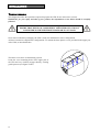
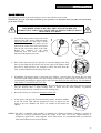
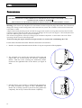
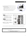
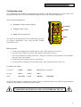
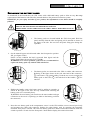
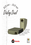
GB SAFETY GB This part of the manual contains precautions that must be adhered to strictly since they regard SAFETY. a) THE UPS MUST NOT OPERATE WITHOUT AN EARTH CONNECTION. The first connection to be carried out is the earth conductor, which has to be connected to the terminal marked . b) Avoid connecting the output neutral to the input neutral or to earth as this could cause malfunctions. c) DANGEROUS electrical voltages are generated inside the UPS. All installation and maintenance operations must be carried out EXCLUSIVELY by authorized personnel. d) The UPS contains an internal power source: the batteries. The terminals and the output sockets may be powered even when the UPS is not connected to the mains. e) The total battery voltage can generate an electric shock. Replaced batteries should be considered as TOXIC WASTE and treated as such. Do not throw the battery packs into fire: they may explode. Do not try to open the battery packs: they do not require any maintenance. Furthermore the electrolyte is dangerous if it comes into contact with the skin or the eyes and may be toxic. f) Do not switch the UPS on if there is any leak of liquid, or if a residual white powder is noted. g) Do not allow water, liquids in general and/or other foreign bodies to get into the UPS. h) In the event of dangerous conditions switch the UPS off with the switch located on the front panel and open the magneto-thermal protection installed upstream of the UPS. Isolate the battery by removing the lower part of the front panel and disconnecting the two battery pack connectors. i) The UPS generates a leakage current of less than 2 mA. Warning: the leakage current of the load is added to that of the UPS on the earth protection conductor. j) For battery expansion use exclusively connectors supplied by or authorized by the manufacturers. k) The UPSs of this series have been designed for professional use and are therefore not suitable for use in a domestic environment. WARNING: this Uninterruptible Power System (UPS) is a class A product (in accordance with standard EN50091-2: UPS - EMC requirement). It may cause radio interference in domestic environments: the user may need to take additional measures against this. 4 GB USER’S MANUAL GB 5 INTRODUCTION Thanks you for choosing our product. Our manifacturer are renowned specialists in the development and production of uninterruptible power supplies (UPS). The UPS in this range are high quality products, designed and built with care in order to give you the best performance. This equipment can be installed by anyone, subject to CAREFULLY AND THOROUGHLY READING THIS MANUAL. The manual contains detailed instructions on how to use and install the UPS. For information on using and getting the best performance from your UPS, this manual should be kept safely in the vicinity of the UPS and CONSULTED BEFORE TAKING ANY ACTION ON THE UPS. © Reproduction of any part of this manual, including partial, is strictly prohibited without the prior consent of the manufacturer. For the purpose of improving it, the manufacturer reserves the right to modify the product described herein at any time and without notice. Microsoft, Windows, and the Windows logo are trademarks, or registered trademarks of Microsoft Corporation in the United States and/or other countries. 6 CONTENTS PRESENTATION 8 UPS VIEWS 9 DISPLAY MASK VIEW INSTALLATION 10 11 OPENING THE PACKING AND CHECKING CONTENTS 11 TOWER VERSION 12 RACK VERSION 13 USE 14 CONNECTIONS 14 FIRST START-UP 16 START-UP FROM MAINS 16 START-UP FROM BATTERY 16 UPS SHUTDOWN 16 DISPLAY PANEL INDICATIONS 17 UPS status indicators 17 Measurements display area 18 Configuration area 19 MODES OF OPERATION 20 R.E.P.O. 20 PROGRAMMABLE AUXILIARY SOCKET (POWER SHARE) 20 UPS CONFIGURATION 21 COMMUNICATION PORTS 23 RS232 and USB connectors 23 Communication Slot 23 SOFTWARE 24 Monitoring and control software 24 Configuration software 24 BATTERY PACK REPLACING THE BATTERY PACKS PROBLEM SOLVING ALARM CODES TECHNICAL DATA TABLE 25 25 26 28 30 7 PRESENTATION This new family of UPSs has been designed with versatility in mind. These UPSs can in fact be installed either in a tower version or in a rack version, according to requirements. The 2 different versions of the product are shown below: Tower Rack The UPS is also provided with two dedicated battery packs that allow the easy hot swap replacement of the batteries in full safety thanks to the protected connection system. DLD 500 Nominal power Nominal voltage Dimensions H x L x D Weight (1) DLD 600 5000 6000 220 / 230 / 240 455 x 175 x 660 (1) 64 The H dimension is different in the rack version with handles mounted: 483mm x 175mm x 660mm (H x L x D) Note: 175mm = 4U 483mm = 19” 8 [VA] [Vac] [mm] [Kg] PRESENTATION UPS VIEWS Release slots Rotatable display mask Manual by-pass switch Main switch Battery pack Removable front panel Cable with terminal Cable with terminal Battery pack Front view (front panel off) Fan RS232 communication port (front panel on) Battery expansion connector COMMUNICATION SLOT (expansion) IEC 10A Power share sockets USB communication port Remote Emergency Power Off. (R.E.P.O.) Power share sockets heat protection IN / OUT connections box Rear view 9 PRESENTATION DISPLAY MASK VIEW “SEL / SET” button “ON” button 11 “STBY” button 9 10 8 1 LCD Display 2 3 4 5 6 7 1 Operating normally 7 Configuration area 2 Operating on mains power 8 Maintenance action required 3 Operating on battery power 9 Timer 4 Load powered from bypass 10 Measurements display area 5 Battery back-up indicator 11 Stand-by/alarm 6 Load level indicator 10 INSTALLATION OPENING THE PACKING AND CHECKING CONTENTS After opening the pack, the first thing to do is make a check of the contents. The pack should contain: UPS 2 plastic keys to release display 2 cable guides Probes for cables – terminal board connection Handles kit 3 plastic covers (top panels) RS232 serial cable User manual + CD-ROM with software User's manual 11 INSTALLATION TOWER VERSION This chapter describes the operations required to prepare the UPS for use in the tower version. WARNING: for your safety and that of your product, the information set out below should be carefully followed. BEFORE CARRYING OUT THE FOLLOWING SEQUENCE OF OPERATIONS, ENSURE THAT THE UPS IS COMPLETELY SWITCHED OFF AND NOT CONNECTED TO THE ELECTRICITY MAINS OR TO ANY LOAD Once removed from the packaging, the UPS is ready for installation in tower configuration. All that is needed to complete this configuration is to mount the three plastic covers provided in the upper part of the UPS, as described below: The three covers have an interlocking system: locate the cover mounting holes in the upper part of the UPS and very carefully engage them by exerting gentle pressure (see figure at side). 12 INSTALLATION RACK VERSION This following describes the work needed to convert the UPS into rack version. WARNING: for your own safety and that of your product, it is important that you follow the instructions given below exactly. BEFORE PROCEEDING TO PERFORM THE SEQUENCE OF OPERATIONS DESCRIBED, MAKE SURE THAT THE UPS IS SWITCHED OFF COMPLETELY AND IS NOT CONNECTED TO THE ELECTRICAL MAINS OR LOAD OF ANY KIND 1 - First and foremost, remove the 4 feet on the bottom of the UPS. Set the UPS horizontal, taking the utmost care and using a small, flat blade screwdriver lift gently the pin placed in the centre of the foot. Once raised, take the pin out from the base of the UPS. Repeat this sequence for the other remaining feet. The exact sequence is depicted in the figure to the side: 1 2 2 - With all the feet removed, now proceed to rotate the display mask. Slip the keys provided into the release slots on the sides of the display mask and exert a slight pressure, just enough to release the mask from the UPS, as demonstrated in the drawing on the side. 3 - WARNING: The display mask is connected to the UPS by a special cable. This means that you must extract the mask taking extreme care and avoiding violent jerks or other brusque movements, so as to avoid possibly damaging the display and/or the UPS. DO NOT TRY IN ANY WAY TO SEPARATE THE DISPLAY MASK FROM THE UPS. 4 - Rotate the mask by 90° in the anti-clockwise direction and fasten it to the UPS again, inserting it gently into the housing until a slight clicking noise is heard and the mask remains in position. NOTE: pressure must be exerted close to the coupling slots. 5 - Rotate the UPS by 90° clockwise taking the utmost care. 6 - At this point, with the UPS in the horizontal position, attach the handles to the side of the UPS with the appropriate screws as depicted in the figure to the side. (handles and screws are include in the handles kit option) NOTE: The UPS is compatible with assembly in standard rack cabinets of 600mm x 800mm or greater (in depth). In rack type installation, given the weight of the UPS, use of the support brackets is compulsory (guide with L-shape support). For the same reason, it is recommended that you install the UPS in the bottom part of the rack cabinet. 13 USE CONNECTIONS INSTALLATION MUST BE CARRIED OUT EXCLUSIVELY BY QUALIFIED PERSONNEL. THE FIRST CONNECTION TO BE CARRIED OUT IS THE PROTECTION CONDUCTOR (EARTH CABLE), TO BE INSERTED IN THE TERMINAL MARKED . THE UPS MUST NOT BE OPERATED WITHOUT BEING CONNECTED TO THE EARTHING SYSTEM. Warning: if the neutral (N) and phase (F) instructions are observed for the plugs and sockets, the UPS will not change the existing neutral arrangements when inserted in a system. The resistance on the neutral connection is less than 0.1 ohm. A differential switch placed upstream will also be triggered for a fault occurring downstream of the UPS. The sensitivity of this switch has to take into account the leakage current of the unit (approx. 2 mA) and of the load which are added together on the UPS earth conductor. The neutral arrangements will only be changed if an isolation transformer is connected or when the UPS is operating with the neutral isolated upstream. Avoid connecting the output neutral to the input neutral or to earth as this could damage the UPS . For the mains and load connections follow the instructions set out below: 1. Install a 32A magneto-thermal switch with B or C trip curve upstream of the equipment. 2. The terminals to be used for the connection of the input and output lines are located inside the IN/OUT connections drawer. Undo the screw securing the connections drawer located on the right-hand side of the drawer (see figure at side). 3. Pull the drawer out as much as is needed for the terminals to be easily accessible (see figure at side). WARNING: the drawer has a locking system to prevent it being pulled out completely. Do not try to remove the drawer completely. 14 USE 4. Use 3-pole cables with 4 mm2 section. With reference to the figure shown at the side: - Insert the cable from the 32A magneto-thermal switch into cable guide P1 (input line). - Insert the cable from the load into cable guide P2 (output line). - Strip the cables observing the measurements provided. - Insert the stripped end in the terminals provided. P2 P1 5. Connect the wires to the relative terminals strictly following the instructions set out below: Input line a - Ensure that the magneto-thermal switch upstream is open. b - Connect the earth wire to terminal 3. c - Connect the neutral wire to terminal 1. d - Connect the phase wire to terminal 2. B y- P a s s M a n ut e n z i o n e R emoto Remote Maintenance By-Pass Output line a - Connect the earth wire to terminal 4. b - Connect the neutral wire to terminal 5. c - Connect the phase wire to terminal 6. 6. Ensure that a jumper is connected at terminals 7 and 8; this is needed for the correct operation of the UPS. 8 7 6 5 4 3 2 1 7. Secure the cable guides to the flange, close the drawer and secure it with the screw removed previously. A WARNING LABEL MUST BE AFFIXED TO ALL MAINS POWER ISOLATING SWITCHES INSTALLED FAR FROM THE UPS AREA, IN ORDER TO REMIND SUPPORT SERVICE PERSONNEL THAT THE CIRCUIT IS CONNECTED TO A UPS. THE LABEL MUST CARRY THE FOLLOWING MESSAGE: ISOLATE THE UNINTERRUPTIBLE POWER SYSTEM (UPS) BEFORE WORKING ON THIS CIRCUIT 15 USE FIRST START-UP 1) Ensure that all the operations described in the paragraph above, “Connections”, have been carried out correctly. 2) Close the magneto-thermal switch located upstream of the UPS. 3) Press the general switch located on the front panel. 4) The UPS will start up after a few seconds; the display comes on, a beep is emitted and the icon will flash. The UPS is now in stand-by state: this means that the UPS is in a minimum consumption condition. The microcontroller is powered and carries out monitoring and autodiagnostic tasks; the batteries are charging; everything is ready to activate the UPS. There is also a stand-by state during operation from battery if the timer is activated. 5) Check the settings on the display (see paragraph: Configuration area) START-UP FROM MAINS 1) Press the “ON” button. When this is pressed all the icons on the display light up for 1 second and the UPS emits a beep. 2) Switch on the equipment connected to the UPS. Only for the first start-up: after approx. 30 sec., check that the UPS is operating correctly: 1. Simulate a black-out by opening the switch connected upstream of the UPS. 2. The load must continue to be powered, the icon should appear on the display and a beep should be heard every 4 seconds. 3. If the switch upstream is closed again the UPS must go back to operating from the mains. START-UP FROM BATTERY 1) Press the general switch located on the front panel. 2) Keep the “ON” button pressed for at least 5 seconds. All the icons on the display will light up for 1 second and the UPS will emit a beep. 3) Switch on the equipment connected to the UPS. UPS SHUTDOWN To switch the UPS off, keep the “STBY” key pressed for at least 1.5 seconds. The UPS will return to the standicon will start to flash: by condition and the a. If the mains is present, the general switch must be pressed so that it returns to its original position (raised position) to switch the UPS off completely. b. If the UPS is operating from battery and the timer has not been set, it will automatically switch off completely after 5 seconds. If however the timer has been set, the “STBY” key has to be pressed for at least 5 seconds to switch off the UPS. If it is required for the UPS to stay completely switched off when mains power returns, the general switch has to be pressed (see point a.). 16 a. USE DISPLAY PANEL INDICATIONS This chapter will describe in depth all the items of information that may be posted on the LCD. For easier understanding, we can divide the information displayed into three main groups: ¾ UPS status indicators ¾ Measurements display area ¾ Configuration area UPS status indicators ICON STATUS DESCRIPTION Fixed Indicates presence if a problem Blinking The UPS is in stand-by mode Fixed Indicates UPS operating normally Fixed The UPS is working on mains power Blinking The UPS working on mains power, but the output voltage is not synchronized with the mains voltage Fixed The UPS is working on battery power. When in this condition, the UPS emits a beep at 4-second regular intervals. Blinking End of discharge early warning. Indicates that the battery’s back-up is running out. In this condition, the UPS emits a beep at 1-second regular intervals. Fixed Indicates that the loads connected to the UPS are being powered by the bypass Dynamic Indicates the estimated percentage back-up Dynamic Indicates the % load applied to the UPS with respect to the nominal value Blinking Maintenance action is needed Fixed Blinking Indicates that the timer is activated (programmed switch-on or switchoff). The timer can be activated/de-activated through the software supplied 1 minute to go before the UPS is switched on again or 3 minutes until it is switched off 17 USE Measurements display area The most important measurements relating to the UPS may be displayed on the display screen. When the UPS is switched on, the display shows the mains voltage value. To move on to display something else, press the “SEL / SET” button repeatedly until the desired measurement value appears. If a failure/alarm occurs (FAULT) or the machine stops (LOCK), the display will automatically display the type of problem and the corresponding alarm code. A number of examples are shown below: SAMPLE GRAPHIC (1) DESCRIPTION SAMPLE GRAPHIC (1) DESCRIPTION Mains voltage Total battery voltage Mains frequency Percentage load applied UPS output voltage Current absorbed by the load Output voltage frequency Temperature of the cooling system of the UPS internal electronics Remaining battery backup Fault / Alarm (2): the corresponding code is displayed Battery charge percentage Lock (2): the corresponding code is displayed (1) The values given in the pictures of the table are purely indicative. (2) The FAULT / LOCK codes will only be displayed if they are active at that time (in presence of a failure/alarm or machine stoppage). 18 USE Configuration area The configuration area contains the main operating parameters of the UPS and displays its current status. The parameters found in this area can be modified by taking action directly from the display panel. SETTABLE PARAMETERS: Frequency: output voltage frequency Frequency Voltage: Output voltage Mode: UPS operating mode Voltage Mode The picture to the side depicts the area of the display reserved for settings (configuration area), with the three settable parameters in view. How to proceed: To enter the configuration area hold down the “SEL / SET” button for at least 2 sec. The word “SET” lights and an arrow ( ► ) appears to the left of Frequency. The arrow indicates the setting selected. To change the selection of the parameter to be modified, press the “SEL / SET” button. To change the item selected, press the “ON” button. To exit from the configuration area, hold the “SEL / SET” button down for at least 2 sec. POSSIBLE SETTINGS Frequency: □ 50 Hz □ 60 Hz □ Off (frequency self-teach) Voltage: □ 220 V □ 230 V □ 240 V Mode: □ ON LINE □ ECO □ SMART □ STBYOFF NOTE: For the change in configuration of output frequency to become effective, the UPS must be switched off completely and switched on again (by the main switch). THE PARAMETERS VOLTAGE AND OUTPUT FREQUENCY MUST BE COMPATIBLE WITH THOSE OF THE LOAD POWERED BY THE UPS 19 USE MODES OF OPERATION The mode that gives the load maximum protection is ON LINE mode (default), where the energy intended for the load undergoes a double conversion and is reconstructed on the output in a perfectly sinusoidal way with frequency and voltage fixed by the precision digital control provided by a microprocessor fully independently of the input (V.F.I.). * Besides the traditional ON LINE double conversion operating mode, it is also possible to set the following modes: ¾ ECO (LINE INTERACTIVE) ¾ SMART (SMART ACTIVE) ¾ STBYOFF (STAND-BY OFF) For optimized efficiency, in ECO mode, the load is powered normally from the bypass. If the mains exits from its specified tolerances, the UPS switches to the normal ON LINE double conversion operating mode. About five minutes after the mains has returned inside tolerance, the load is again switched to bypass. Where a user is unable to decide between the most suitable operating mode (ON LINE or ECO), he can leave the choice to SMART ACTIVE mode in which, in relation to statistics regarding the quality of the mains power supply, the UPS autonomously decides which mode to configure itself in. Finally in STAND-BY OFF mode, operation is as a back-up device: with mains line present, the load is powered down, whereas when a black-out occurs the load is powered by the inverter through the batteries. R.E.P.O. This isolated input is used to switch off the UPS remotely in an emergency. Any “Remote Emergency Power Off” (R.E.P.O.) switch that is normally closed must be connected to the connector located at the back of the UPS. The UPS is supplied ex-works with the R.E.P.O. terminals short circuited: remove the short circuit if this contact is connected to the auxiliary of a remote emergency switch. The R.E.P.O. circuit is self-powered with SELV type circuits. No external power supply voltage is therefore required. When it is closed (normal condition) there is a current of 10mA max. PROGRAMMABLE AUXILIARY SOCKET (POWER SHARE) The UPS is provided with an output socket that allows the automatic disconnection of the load applied to it under certain operating conditions. The events that determine the automatic cut-out of the Power share socket can be user-selected by means of the UPSTools configuration software (see paragraphs Configuration software and UPS Configuration). It is possible for example to select cut-out after a certain time of operation from battery, or on reaching the end of battery discharging prealarm threshold, or in the event of an overload. * The rms value of the output voltage is fixed by accurate microprocessor control independently of the input voltage while the frequency of the output voltage is synchronized (within a user-selectable tolerance) with that of the input to enable use of the bypass. The UPS will desynchronize outside of this tolerance, returning to nominal frequency, and the bypass can no longer be used (free running mode). 20 USE UPS CONFIGURATION The following table illustrates all the possible configurations that users have at their disposal to best adapt the UPS to their needs. LEGEND: = Indicates that the configuration can be modified, both via the configuration software supplied and also by means of action on the display panel. = Indicates that the configuration can be modified only through the configuration software supplied. FUNCTION DESCRIPTION Output frequency Selects the nominal output frequency PREDEFINED Auto POSSIBLE CONFIGURATIONS • 50 Hz • 60 Hz • Auto: automatic self-teaching of the input frequency • • • • 220V 230V 240V 220 ÷ 240 in steps of 1V (only through the software) • • • • ON LINE ECO SMART ACTIVE STAND-BY OFF Output voltage Selects the nominal output voltage Operating mode Selects one of the 4 different modes of operation ON LINE Switch-on delay Delay time for automatic switching on again after the mains returns 5 sec. Switch-off due to minimum load Automatic UPS switch-off when in battery-powered operation, if the load is less than 5% Disabled • Enabled • Disabled Back-up limitation Maximum battery operation time Disabled • Disabled (full battery discharge) • 1 ÷ 65000 in steps of 1 sec. End of discharge early warning Estimated remaining back-up time for the end of discharge early warning 3 min. 1 ÷ 255 in steps of 1 min. Battery test Time interval for the automatic battery test 40 hours • Disabled • 1 ÷ 1000 in steps of 1 hour 230V MODE • Disabled • 1 ÷ 255 in steps of 1 sec. 21 USE FUNCTION DESCRIPTION PREDEFINED Alarm threshold for maximum load Selects the overload user limit Disabled Display brightness Selects the level of brightness of the LCD Maximum Minimum ÷ Maximum in 20 steps Sound alarm Selects the mode of operation of the sound alarm Reduced • Normal • Reduced: does not sound for momentary intervention of the bypass Always connected • Always connected • Cut-out after n seconds of operation from battery • Cut-out after n seconds from the end of discharge prealarm signal • ... (see UPSTools manual) Auxiliary socket (power share) Selects the operating mode of the auxiliary socket POSSIBLE CONFIGURATIONS • Disabled • 0 ÷ 103 in steps of 1% ADVANCED FUNCTIONS Input frequency tolerance Selects the permitted range for the input frequency for switchover to bypass and for output synchronization ± 5% Bypass voltage thresholds Selects the permitted voltage range for switchover to bypass Low: 180V High: 264V Bypass voltage thresholds for ECO Selects the permitted Low: 200V voltage range for ECO High: 253V mode operation Sensitivity of intervention for ECO mode Selects the sensitivity of intervention during operation in ECO mode Normal Load power supply in standby Power supply of the load on bypass with UPS switched of (stand-by status) Disabled (load NOT powered) Bypass operation 22 Selects the mode for use of the bypass line Normal • • • • ± 0.25% ± 0.5% ± 0.75% ± 1 ÷ ±10 in steps of 1% Low : High: 180 ÷ 200 in steps of 1V 250 ÷ 264 in steps of 1V Low:180 ÷ 220 in steps of 1V High: 240 ÷ 264 in steps of 1V • Low • Normal • High • Disabled (not powered) • Enabled (powered) • Normal • Disabled with input/output synchronization • Disabled without input/output synchronization MODE USE COMMUNICATION PORTS The following communication ports are found on the rear of the UPS (see UPS Views): ¾ Serial port, available with RS232 connector and USB connector. NOTE: use of one connector automatically excludes the other one. ¾ Expansion slots for additional COMMUNICATION SLOT interface cards. RS232 and USB connectors RS232 CONNECTOR USB CONNECTOR 6 7 8 9 4 3 1 2 1 2 3 4 5 PIN # 1 2 3 4 5 6 7 8 9 SIGNAL Contact closed: UPS stopped * TXD RXD PIN # 1 2 3 4 SIGNAL VBUS DD+ GND GND +12Vdc interface power supply input Contact closed: end of discharge early warning * Contact closed: battery-powered operation * * Optoisolated contact max. +30Vdc / 10mA Communication Slot The UPS is provided with an expansion slot for optional communication cards (see the figure to the side) that enable the machine to carry out dialog using the main communication standards. Some examples: • Second RS232 port • Serial port duplexer • Ethernet network agent with TCP/IP, HTTP and SNMP protocol • RS232 + RS485 port with JBUS / MODBUS protocol • Signalling relay card UPS For more information on the accessories available, consult the manufacturer’s web site. 23 USE SOFTWARE UPS PC RS232 Monitoring and control software The PowerShield2 software provides effective and intuitive management of the UPS, displaying all the most important information, such as input voltage, load applied, and battery capacity. It is also able to automatically effect operations such as shutdown, transmission of e-mails, SMS and network messages when particular events that can be selected by the user occur. Installation procedure: • Connect the UPS’s RS232 communication port to a COM communication port on the PC by means of the serial cable provided* or connect the USB port on the UPS to a USB port on the PC using a USB standard cable*. • Insert the CD-ROM and select the desired operating system. • Follow the instructions of the installation program. • For more detailed information about installation and use, see the software user manual in the Manuals folder of the CD-ROM supplied. To check if a more up to date version of the software is available, visit the manufacturer’s web site. Configuration software The UPSTools software may be used for configuration and full display of the parameters and status of the UPS through the RS232 serial port. For a list of the possible configurations at the user’s disposal, see the section UPS Configuration. Installation procedure: • Connect the RS232 communication port of the UPS to a COM communication port on the PC by means of the serial cable provided*. • Follow the instructions on installation found in the software user manual in the UPSTools folder of the CD-ROM supplied. To check if a more up to date version of the software is available, visit the manufacturer’s web site. * You are advised to use a cable of max. length 3 metres. 24 BATTERY PACK REPLACING THE BATTERY PACKS As mentioned in the introduction, the UPS comes with a dedicated battery pack to allow an easy hot swap replacement of the batteries with full safety ensured thanks to the protected connection system. WARNING: for your safety and that of your product, the information set out below should be carefully followed. WHEN THE BATTERY PACK IS DISCONNECTED, THE LOADS CONNECTED TO THE UPS ARE NOT PROTECTED FROM MAINS FAILURE. THE BATTERY PACK IS VERY HEAVY. BE VERY CAREFUL WHEN REPLACING IT. 1. The battery packs are located behind the UPS front panel. Hold the panel centrally from the sides and gently pull it outwards as shown in the figure at the side. Do not force the panel fixing pins during this operation. 2. Set the manual bypass switch located under the front panel to position “II” (see figure at side). NOTE: in this condition the load is powered from bypass and the display should show the message FAULT: C02. WARNING: For correct operation of the UPS it is recommended to replace the battery pack only with the UPS switched on. C A B 3. The battery packs are connected to the UPS via cables with connector. Referring to the figure shown at the side: take hold of the connector ( A ) and remove it by gently pulling. Undo the two screws securing the battery pack to the UPS ( B ) and take hold of the handle ( C ) for removal. 4. Holding the handle, remove the battery pack by pulling it outwards, as shown in the figure at the side. Be very careful when extracting the battery pack as it is extremely heavy. WARNING: the new battery pack must have the same number and type of batteries as the one it is replacing (see label on the battery pack near the connector). 5. Insert the new battery pack in the compartment, secure it to the UPS with the screws removed previously and reconnect the cable with connector. Replace the other battery pack by repeating the operations described from point 3 onwards. Once the new battery packs have been secured and connected, return the switch to position “I” and close the front panel. Check that the display has returned to normal. 25 PROBLEM SOLVING Irregular functioning of the UPS is very often not an indication of a fault but due simply to trivial problems, minor difficulties or carelessness. We therefore recommend that you refer to the table below which gives a summary of useful information to solve the most common problems. PROBLEM POSSIBLE CAUSE GENERAL SWITCH NOT PRESSED THE BATTERY PACK CONNECTOR IS DISCONNECTED THE DISPLAY DOES NOT SWITCH ON NO CONNECTION TO THE ELECTRICITY MAINS MAINS VOLTAGE FAILURE (BLACK-OUT) THE DISPLAY IS ON BUT THE LOAD IS NOT POWERED THE UPS IS OPERATING FROM BATTERY EVEN THOUGH THE MAINS VOLTAGE IS PRESENT SOLUTION Press the general switch located on the front panel. Connect the battery pack connector by following the instructions set out in the paragraph “REPLACING THE BATTERY PACK”. Check the connection to the electricity mains. Check the presence of the electricity mains voltage. UPSTREAM PROTECTION TRIGGERED Reset the protection. WARNING: Check that there is no overload in output to the UPS. THE UPS IS IN STAND-BY MODE Press the “ON” key located on the front panel to power the loads. STAND-BY OFF MODE HAS BEEN SELECTED The mode has to be changed. The STAND-BY OFF mode (back-up) in fact only powers the loads in the event of a black-out. NO CONNECTION TO THE LOAD Check the connection to the load. UPSTREAM PROTECTION TRIGGERED Reset the protection. WARNING: Check that there is no overload in output to the UPS. THE INPUT VOLTAGE IS OUTSIDE THE ALLOWED TOLERANCE FOR OPERATION FROM MAINS Problem dependent on the mains. Wait for the input mains to return within tolerance. The UPS will automatically go back to operation from mains. THE UPS DOES NOT SWITCH ON AND THE DISPLAY SHOWS ONE OF THESE CODES: A06, A08 THE TEMPERATURA OF THE UPS is located; if it is too low, bring it to above the UPS IS LOWER THAN 0°C THE DISPLAY SHOWS THE CODE: A11 INPUT RELAY BLOCKED 26 Check the temperature of the environment where the minimum threshold (0°C). The fault does not cause any particular malfunctions. If the problem should occur again on a subsequent startup, contact the support service centre. PROBLEM SOLVING PROBLEM THE BUZZER SOUNDS CONTINUOUSLY AND THE DISPLAY SHOWS ONE OF THESE CODES: A54, F50, F51, F52, F55, L50, L51, L52 POSSIBLE CAUSE SOLUTION THE LOAD APPLIED TO THE Reduce the load to within the threshold of 100% (or UPS IS TOO HIGH user threshold in the case of code A54). THE DISPLAY SHOWS THE CODE: A61 BATTERIES SHOULD BE REPLACED Replace the battery packs (as indicated in the chapter BATTERY PACK). THE DISPLAY SHOWS THE CODE: A62 BATTERY PACKS NOT PRESENT OR NOT CONNECTED Check that the battery packs are inserted and connected correctly (see chapter BATTERY PACK). THE DISPLAY SHOWS THE CODE: A63 THE BATTERIES ARE DISCHARGED; THE UPS IS WAITING FOR THE VOLTAGE OF THE BATTERIES TO GO OVER THE SET THRESHOLD Wait for the batteries to recharge or force start-up manually by keeping the “ON” key pressed for at least 2 sec. THE BUZZER SOUNDS CONTINUOUSLY AND THE A MALFUNCTION OF THE If power can be removed from the load, switch the UPS DISPLAY SHOWS ONE OF UPS HAS BEEN VERIFIED; off and then on again; if the problem should occur THESE CODES: F03, F05, PROBABLY ABOUT TO STOP again, contact the support service centre. F07, F10, F13, F21, F40, F41, F42, F43 THE BUZZER SOUNDS THE TEMPERATURS OF THE Check that the temperature of the environment where CONTINUOUSLY AND THE DISSIPATORS INSIDE THE DISPLAY SHOWS ONE OF the UPS is located does not exceed 40°C. UPS IS TOO HIGH THESE CODES: F04, L04 THE BUZZER SOUNDS CONTINUOUSLY AND THE DISPLAY SHOWS ONE OF THESE CODES: F53, L53 A FAULT HAS BEEN DETECTED ON ONE OR MORE APPLICATIONS POWERED BY THE UPS THE BUZZER SOUNDS CONTINUOUSLY AND THE DISPLAY SHOWS ONE OF THESE CODES: F60, L03, L05, L07, L10, L13, L20, L21, L40, L41, L42, L43 A MALFUNCTION OF THE UPS HAS BEEN VERIFIED If power can be removed from the load, switch the UPS off and then on again; if the problem should occur again, contact the support service centre. A REMOTE CONTROL HAS BEEN ACTIVATED If this is not required, check the position of the manual bypass switch or the status of the control inputs of any optional contacts card. Check the closing of the R.E.P.O. contact at the back of the UPS. THE DISPLAY SHOWS ONE OF THESE CODES: C01, C02, C03 Disconnect all the applications and reconnect them one by one to identify the faulty one. 27 PROBLEM SOLVING ALARM CODES By using a sophisticated self-test system, the UPS can check and report on the display panel any problems and/or failures that could occur during normal operation of the equipment. In case of a problem, the UPS signals the event by posting on the display the code and type of alarm present (FAULT and/or LOCK). FAULT The FAULT type reports may be divided into three categories. ¾ Failures: these are “minor” problems that do not result in the UPS stopping but they limit its performance or prevent certain features being used. CODE DESCRIPTION A06 A08 A11 A54 A61 A62 A63 Temperature sensor1 less than 0°C Temperature sensor2 less than 0°C Input relay stuck (does not open) Load > threshold set by user Batteries need replacement Battery pack missing or not connected Waiting for batteries to recharge ¾ Alarms: these problems are more critical than the failures because – if they continue – they could cause the UPS to stop, even in a very short time frame. 28 CODE DESCRIPTION F03 F04 F05 F07 F10 F13 F21 F40 F41 F42 F43 F50 F51 F52 F53 F55 F60 Auxiliary power supply incorrect High temperature on heat sinks Temperature Sensor1 broken Temperature Sensor2 broken Input fuse broken or input relay stuck (does not close) Capacitor precharging failure Capacitor bank overvoltage Inverter overvoltage D-C voltage on output Inverter voltage not right Inverter undervoltage Overload: load > 103% Overload: load > 110% Overload: load > 150% Short-circuit Waiting for load reduction before return to inverter Battery overvoltage PROBLEM SOLVING ¾ Commands in progress: indicates presence of a remote command in progress. CODE DESCRIPTION C01 C02 C03 C04 Remote shutdown command Remote load on bypass command Remote switch-on command Battery test in progress LOCK The LOCK (block) type report signals are usually preceded by an alarm signal and, on account of their importance, result in the inverter being switched off and the load being powered through the bypass line (the procedure is excluded in case of lockouts due to strong and persistent overloads and lockouts following a shortcircuit). CODE DESCRIPTION L03 L04 L05 L07 L10 L13 L20 L21 L40 L41 L42 L43 L50 L51 L52 L53 Auxiliary power supply incorrect High temperature on heat sinks Temperature Sensor1 broken Temperature Sensor2 broken Input fuse broken or input relay stuck (does not close) Capacitor precharging failure Capacitor bank undervoltage Capacitor bank overvoltage Inverter overvoltage D-C voltage on output Inverter voltage not right Inverter undervoltage Overload: load > 103% Overload: load > 110% Overload: load > 150% Short-circuit 29 1- TECHNICAL DATA TABLE DLD 500 MODELS INPUT Nominal voltage Nominal frequency Accepted range Voltage and frequency range for non intervention of the battery Maximum current (1) Nominal current (2) Power factor Current distortion @ maximum load BYPASS Accepted voltage range for switching Accepted frequency range for switching Switching time BATTERY No. batteries / V / Ah Recharge time OUTPUT Nominal voltage (8) Maximum current Static variation (4) Dynamic variation (5) Waveform Voltage distortion @ linear load Voltage distortion @ distorting load (3) Frequency (6) Current crest factor Nominal power (3) Nominal power MISCELLANEOUS Leakage current to earth AC/AC efficiency Ambient temperature (7) Humidity Protections [Vac] 220 - 230 - 240 [Hz] 50 – 60 [Vac] 0 ÷ 276 [Vac] Maximum: 276 [Vac] Minimum: 164 ÷ 84 (from 100% to 50% of load in linear mode) [Vac] Return to mains-powered operation: 180 [Hz] Frequency: 40 ÷ 72 [A] 25 30 [A] 18 22 ≥ 0.98 ≤ 6% [Vac] [msec] [h] [Vac] [A] [VA] [W] [mA] [°C] Safety compliance EMC compliance Hold-up time Noise level Dimensions H x L x D Weight 30 DLD 600 [msec] [mm] [Kg] 180 ÷ 264 Frequency selected ±5 % 0,1 16 / 12 / 7 high rate discharge 4÷6 220 / 230 / 240 ±1.5% 23 / 22 / 21 27 / 26 / 25 1.5% ≤ 5% in 20 msec Sinusoidal ≤ 3% ≤ 5% 50 or 60 Hz selectable ≥3:1 5000 6000 3500 4200 ≤2 > 91% 0 – 40 < 90% non-condensing Excessive battery discharge – Overcurrent – short-circuit – Overvoltage – undervoltage - thermal EN 50091-1-1 and directive 73 / 23 / EEC, 93/68 EEC EN 50091 - 2 cl. A and directive 89/336 EEC, 92/31 EEC, 93/68 EEC ≥ 35 < 45 dB(A) at 1 mt. 455 x 175 x 660 (10) 64 2- TECHNICAL DATA TABLE OPERATION POWERED BY OVERLOAD TIMES BYPASS INVERTER 100% < Load ≤ 110% Activates bypass after 2 sec Stoppage after 120 sec Stoppage after 60 sec 110% < Load ≤ 150% Activates bypass after 2 sec Stoppage after 4 sec Stoppage after 4 sec Load > 150% Activates bypass instantaneously Stoppage after 1 sec Stoppage after 0.5 sec (1) @ nominal load, minimum voltage of 164 Vac, battery charging (2) @ nominal load, nominal voltage of 230 Vac, battery charging (3) According to appendix M5 of standard EN50091-1-1 (4) Mains/Battery @ load 0% -100% (5) @ Mains/battery/mains @ resistive load 0% / 100% / 0% (6) If the mains frequency is within ± 5% of the value selected, the UPS is synchronized with the mains. If the frequency is outside the tolerances or operation is battery-powered, the frequency is the selected frequency +0.1% (7) 20 - 25 °C for longer battery life (8) To maintain the output voltage inside the precision range indicated, a recalibration may be necessary after a long period in operation (9) Time required to reach 90% of the charge (after a full discharge) (10) Corresponding to: 19” x 4U x 26” (H x L x D) 31 0MNUM6KRUA_GB 32