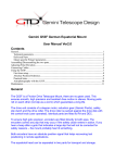
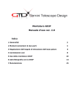
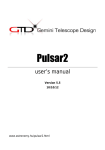
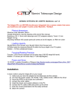
1
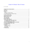
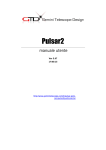
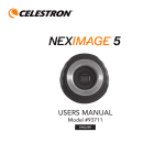
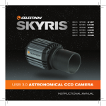
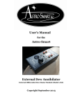
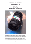
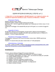
Gemini G53F German Equatorial Mount
User Manual Ver2.1
Contents
General.................................................................................................................................................1
Technical parameters.......................................................................................................................2
Delivered Parts.................................................................................................................................2
Mount specific Pulsar2 parameters..................................................................................................2
Assembling/Disassembling the two parts.............................................................................................3
Adjusting Polar Elevation.....................................................................................................................4
Connecting Cables................................................................................................................................6
Using the G53F.....................................................................................................................................7
First time setup.................................................................................................................................8
Absolute Position Reference............................................................................................................9
Practical hints...................................................................................................................................9
Astrophotography with the G53F..................................................................................................10
Maintenance........................................................................................................................................11
General
The G53F is a Friction Drive Telescope Mount, there are no gears used. This
ensures smooth, high precision and backlash free motion in silence. Moving parts
roll on each other (not slip as a worm) which guarantees a long life.
The drive unit consists of a stepper motor, reduction gear (Gemini Fluido) and the
drive roller. The drive roller is pushed against the drive disk with the torque limited
clutch knob. Identical parts are fitted to RA and DEC.
To ensure high goto precison, encoders are fitted directly to both axes. The
encoders correct any slip that may occur if the drive slips or clutches are opened. If
you hear a beep after a goto that indicates a large slip that will not be corrected for
safety reasons – the mount probably has hit something.
Both encoders have an absolute position signal that helps recovering lost
positioning in remote applications.
The equatorial head can be separated in two parts for transport and storage.
Technical parameters
Steppers: NEMA 17, 400 step, 1,5 Amp
Drive disk: D 220 mm, stainless steel
Drive roller: D 6 mm, hardened and coated steel
Encoders: Optical incremental, 72 000 pulse/rev
Weight: 20 kg
Load capacity: 45 kg
Maximum unbalanced torque: 10 Nm (1kg at 1m radius)
Elevation range: 25-90 deg
Temperature range: -20 to +30
Driver: Pulsar2
Slewing precision: cca +/- 30 arcsec
Max slewing speed with Pulsar2. 4 deg/sec
Tracking precision: 2”/5 minutes
Power: 12-18VDC, 3A (1A continuous draw at 12V)
Telescope interface: Losmandy rail or custom
Delivered Parts
Equatorial head with Losmandy adapter, Counterweight shaft (30mm), Pulsar2 driver with
hand controller, motor cables, encoder cables, power cable with banana plug, cable guide
ring. Optional: counterweights, polar finder, tripod.
Mount specific Pulsar2 parameters
(Non default values only)
Total Red: enter 360, the exact value will be calculated by Pulsar2
Track current: 950mA
GoTo current: 1200mA
Stop current: 400mA or 950 for guided photography
Motor step R/D: 400
Encoders: Mount encoders are fitted (answer Yes to Mount encoder RA and DEC,
answer No to Motor encoder RA and DEC)
Resolution: 72 000 both RA and DEC
Rotation: leave as it is, will be defined by Pulsar2
Umod Sp limit (user parameters) 9900
Ramp (user parameters) Ra 1, Dec 2
Backlash (user parameters):0 arcsec
There are videos on YouTube to help with the setup and other features. Visit this link to see the
updated list: http://www.geminitelescope.com/manuals.html
Assembling/Disassembling the two parts
1 To assemble the equatorial head get ready the parts shown below and the
DEC head. (the 6mm hex key is not delivered)
2 Now place the DEC head into the red saddle as shown below. You can
conveniently hold it with your right hand by reaching into the counterweight
shaft hole. Note the position of the DEC drive unit! (opposing the Ra drive)
3 Put the upper saddle half on the DEC head so that the holes face those in
the lower saddle.
4 Fasten the screws evenly, making sure that the gap between the two saddle
parts is approximately equal on either side. This will have importance if you
put a polar finder on top of the upper saddle.
You are ready now. Disassembling is the reverse of assembling.
Adjusting Polar Elevation
The adjustment range of the elevation screw is cca 20 degrees. If you need
more adjustment you have to reposition the RA head in the elevation plates
as explained below.
1 Remove the DEC head from the RA head. This makes the procedure much
more easy to do.
2 Turn the elevation screw close to the OUT position.
3 Remove both elevation locks and the centering rings which are below the
locks.
4 Pull out backwards the RA head from the fork base.
5 The pin is marked with a blue dot. You must pull the plates away and put
the pins into the correct holes (1 to 4) for your desired latitude. The actual
position (2) is for mid Northern/Southern latitudes, 1 is down to 25 deg, 3 and
4 for far North/South.
6 Push the RA head back into the fork base, insert the centering rings and the
locks, finally mount the DEC head.
1 turn of the elevation screw is cca 0,6 degree change in elevation.
Connecting Cables
You need to connect 3 cables from Pulsar2 to G53F (4 terminals at mount
end). There is a video tutorial also, the link is on our webpage.
Motor cable (1) (DB15 at Pulsar2 end, 2x 4/4 telephone plug at G53F end)
The shorter cable is RA, the longer DEC.
Encoder cables (2) (8/8 UTP at Pulsar2 end, 5pin Tuhel plug at G53F end)
The shorter cable is RA, the longer DEC (only the length is different).
No damage will occur if you swap the cables but the mount will not operate
correctly.
DEC and RA encoder connectors
DEC and Ra motor connectors
Using the G53F
First time setup
If you are using the G53F for the first time or have replaced the Pulsar2
controller check the Mount Parameters in Pulsar2 (and see also the P2
manual). Check if the mount tracks westward, if not change the Rotation
(mount parameters menu)! If all is correct you will want to do the automatic
setup process which calculates the total reduction and the encoder direction.
Insert the counterweight shaft and lock the axes by turning both control knobs
right until you feel strong resistance (cca ½ turn after feeling the build-up of
resistance). The mount is well balanced with the counterweight shaft, remove
any load from the telescope platform.
Correct position for running Red autoset
Enter the Mount Parameters menu, Red (uction) autoset submenu and start
the process. The mount will start rotating slowly cca 45 degrees and back in
both axes. You will have to acknowledge by a right click the calculated values.
(slip factor and reduction). For the slip factor you should get a value above
98%, if it is much lower the balance is off.
When finished, exit the menu, the controller is ready for use.
For loading counterweights and telescopes leave the RA axis open, close the
DEC by turning the DEC control knob right until you hear a click.
For balancing release both axes with the control knob. Try to get a good
balance!
When balanced, lock both control knobs by turning them right until you hear
a click.
Absolute Position Reference
The G53F when used with Pulsar2 can memorize the absolute position signal
of the encoders (sent once in every full rotation of the axes) and use this as a
reference for initializing the mount. You still need to be polar aligned and have
time (UT) and lat/long (in decimals) set correctly. With this feature you can
initialize the G53F remotely, using only an IP camera as your „eyes”.
Select the Set Reference submenu in Mount Parameters and follow the
instructions. You need to have the mount initialized on a star beforehand.You
are asked to slew the mount until the signal has been recieved.
The RA absolute signal is factory adjusted to fall within 2 hours of the
meridian with the OTA on the Western side. If you do not find the reference on the
Western side reverse the dec head in the red saddle!
In Declination the absolute signal is in
the zone of cca -10/+30 deg. This will
allow a safe and convenient initializing
when needed. Note that the Losmandy
lock handknobs must face upwards for
the reference to fall in the above zone.
To initialize the G53F with the encoders
go to the Get Reference submenu in
the User Parameters menu and slew
the mount into the above mentioned
positions as promted by the hand
controller. Reaching the signal is
acknowledged by a beep and the slew
stops automaticly
Practical hints
You can open the axes while the mount is in use and rotate the telescope by
hand but if you do fast movements positioning will partially be lost.
If the mount hits something the integrated slip clutches will protect the drive
system and the telescope from damage. If a goto fails for the above reason
you will hear a beep and there will be no correction. The coordinates will stay
correct.
If the control knobs are lightly locked the drive rollers may slip which
eventually may damage them. To avoid this either open the control knobs
completely (1,5 turns left from locked position) or lock them fully as described
above.
The slewing speed depends on the load you have on the G53F. With a
medium sized telescope (10” SC) you can use 999. For larger loads
experiment with speed, Umod sp limit and ramp to get a reliable result
(reduce speed Umod sp limit and ramp if necessary).
Run the Red Autoset routine (Mount Parameters menu) if the ambient
temperature has changed more than 15 deg C. This ensures the precise
tracking rate.
Before you look for other reasons of goto pointing errors check your polar
alignment. If a 15 min unguided image above +60 deg declination shows no
drift (less than 5 arcsec) you are ok.
After Jan. 2013 the G53F is equipped with autolimiting friction control knobs.
Just turn right the red knob until you hear the „click”! The mount is locked
now. To unlock, turn left one turn.
Astrophotography with the G53F
There are a few things to remember for successful imaging.
1) use the correct guide speed for your pixel scale. E.g. Speed 1-2 for high resolution
(up tp 1.5”/pixel), speed 3-4 for medium and 5 for telephoto imaging.
2) Have stop current set close to track current to avoid jumps in declination
3) Do not let any cables hang off the telescope or camera. Route them all via the
center of the declination head, thru the supplied cable guide ring.
4) Balance the mount as precisely as possible. If you have a Newtonian orient the
focusser exactly facing or opposing the telescope platform. All other positions will
imbalance the telescope in some sky position. If you have a guidescope on the
main tube the same is valid for that.
5) If you have to flip meridian make sure to select the correct direction in Pulsar2.
Setup/User parameters/Pole crossing/Tube rotation. For Newtonians select North,
for all other telescopes that have the camera at the lower end select South. This will
prevent cable problems if you have routed them thru the provided ring.
6) The controller Pulsar2 connects to the computer either as an LX200 non GPS
device or via the ASCOM platform and its dedicated driver. See
www.geminitelescope.com/manuals.html for more help. It has been tested with
MaxIm and Astroart. Do not use an autoguiding cable, connecting the mount via the
serial/usb port gives more precise corrections.
Maintenance
The anodised aluminium surfaces will keep their gloss for a long time if
treated regularly with paraffin oil or silicone oil. Use a soft cloth to disperse
the oil on the surface.
Protect the mount from dust, sand and dirt. If you see dirt on the drive disc,
remove the plastic protection cap and wipe it off with a cotton tip.
No maintenance of the drive system is necessary. For longer periods of
cloudy nights and transport leave the axes disengaged.
Innovation and service since 1996
www.geminitelescope.com