1
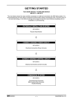
_________________________________________________________ USERS MANUAL MSX2 SERIES SOFT STARTERS ENGINEERED MOTOR CONTROL __________________________________________________________________ ELECTRONIC SOFT STARTERS AND A.C.SPEED DRIVES READ MANUAL COMPLETELY PRIOR TO CONNECTING AND COMMISSIONING THIS EQUIPMENT Fault finding and/or repair of this equipment must be undertaken only by suitably qualified personnel. WARNING LECTRICAL SHOCK HAZARD ENSURE THE MSX2 IS COMPLETELY ISOLATED FROM THE POWER SUPPLY BEFORE ATTEMPTING ANY WORK ON THE UNIT _______________________________________________________ _ AUCOM ELECTRONICS LTD Head Office 123 Wrights Road, Christchurch New Zealand. P.O.Box 21-245, Christchurch New Zealand. Phone : Fax : [64](03)338-8280 [64](03)338-8104 AUCOM ELECTRONICS (AUSTRALIA) PTY LTD Head Office 187 Stanley Street, Melbourne Victoria 3303, Australia. P.O.Box 305, World Trade Centre Victoria 3005, Australia. Phone : Fax : [61](03)328-3335 [64](03)329-1017 AUCOM ELECTRONICS (UK) LTD Head Office Hardy House, Somerset Road, Ashford Kent TN24 8EW, England. Phone : [44](233)643-835 Fax : [44](233)639-320 _______________________________________________________ _ GETTING STARTED THIS USERS MANUAL COVERS MSX2 MODELS MSX2-0011 Ö MSX2-0372 The chart below shows the major activities necessary to install and commission the MSX2 Series starter. It is recommended that all users refer to at least the sections listed, before commencing work. First time users of soft start technology, or the MSX2 are strongly encouraged to read this Users Manual completely prior to installation or commissioning. PHYSICALLY INSTALL THE STARTER refer sections : Physical Specification Ø CONNECT DESIRED POWER CIRCUIT refer sections : Electrical Connection (Power Circuits) Ø CONNECT DESIRED CONTROL CIRCUIT refer sections : Electrical Connection (Control Circuits) Ø COMMISSION STARTER refer sections : Commissioning Procedure MSX2 Programming Procedure Trouble Shooting MSX2 SERIES -- i -- AMM00076 Rev B.2 SECTIONAL INDEX SECTION 1 CAUTION STATEMENTS Details possible causes of equipment damage SECTION 2 GENERAL DESCRIPTION Overview of MSX2 Series SECTION 3 MSX2 FEATURE DESCRIPTIONS - Start Modes Uni-Start TVR Soft Start Current Limit - Tri-Slope Full Voltage - Uni-Stop Soft Stop - Phase Sequence Protection - Control Inputs - Indicators - Relay Outputs - Prestart Circuit Analysis & Configuration - Auto-Reset - Auto-Configuration SECTION 4 ELECTRICAL SPECIFICATION - MSX2 Connection Detail - General Specification - Current Ratings SECTION 5 PHYSICAL SPECIFICATION - Dimensions - Weights - Mounting Precautions - Ventilation : Mounting In Vented Enclosure - Ventilation : Mounting In Non-ventilated Enclosures - Typical Layout Drawings - Control Terminations - DIP Switch set Up Panel SECTION 6 ELECTRICAL CONNECTION (POWER CIRCUIT) - 3 Wire Motor Connection - 6 Wire Motor Connection - Line Contactors - Bridging Contactors - Power Factor Correction MSX2 SERIES -- ii -- AMM00076 Rev B.2 SECTIONAL INDEX SECTION 7 ELECTRICAL CONNECTION (CONTROL CIRCUIT) - MSX2 Control Supply - Control Inputs - Control Outputs - Typical Installation Formats SECTION 8 COMMISSIONING PROCEDURE - Pre-commissioning Checks - Commissioning Procedure SECTION 9 MSX2 PROGRAMMING PROCEDURE - Overview Of MSX2 Adjustments - Programming Procedure SECTION 10 TROUBLE SHOOTING GUIDE Step by Step guide MSX2 SERIES -- iii -- AMM00076 Rev B.2 CAUTION STATEMENTS SECTION 1 CAUTION STATEMENTS Overview : This section highlights potential causes of equipment damage Content : CAUTION Caution List ......................................................................... 1-1 This caution symbol is used throughout the MSX2 Manual to draw special attention to activities which may result in equipment damage. A summary of these cautions is listed below. Such Caution Statements cannot cover every potential cause of equipment damage but can highlight common causes of damage. It is therefore the installers responsibility to adhere to all instructions in this manual, to follow good electrical practice and to seek advice before operating this equipment in a manner other than as detailed in this manual. Ensure that the MSX2 is completely isolated from the power supply before attempting any work on the unit. Entry of metal swarf into the cabinet can cause equipment failure. Do not apply voltage to the MSX2 control input terminals. These are active 24VDC inputs and must be controlled with potential free circuits. Do not connect Power Factor Correction capacitors to the output of the MSX2. If static power factor correction is employed, it must be connected to the supply side of the MSX2. Before installing the MSX2 without a line contactor ensure such connection meets local regulations and by-laws. If installing the MSX2 within a non-ventilated enclosure a by-pass contactor must be utilised to prevent excessive heat build-up. Do not utilise the 6 Wire Motor Connection format without using a line contactor or no volt release circuit breaker. If installing a by-pass contactor ensure phase connections are correctly made ie L1-T1, L2-T2,L3-T3, or L1-L4, L2-L5, L3-L6, or 1-2, 3-4, 5-6 The examples and diagrams in this manual are included solely for illustrative purposes. Users are cautioned that the information contained in this manual is subject to change at any time and without prior notice. In no event will responsibility or liability be accepted for direct or indirect or consequential damages resulting from the use or application of this equipment. MSX2 SERIES 1-1 USERS MANUAL GENERAL DESCRIPTION SECTION 2 GENERAL DESCRIPTION Overview : This section provides overview of MSX2 Seies Content : General Description ............................................................................ 2-1 General Description The MSX2 Series is a microcontroller based soft starter designed to simplify the installation and commissioning of reduced voltage starting systems. The MSX2 Series soft starters offer users a complete solution for their soft starting. Units range from a low 9 Amps right through to 1393 Amp models, all of which, without adjustment, are suitable for use with a wide range of voltages and frequencies. This Users Manual covers MSX2 Series models MSX2-0011 thru MSX2-0372. In operation the MSX2 Series provides : • • • • • soft start of motor and load reduced starting current soft stop of motor and load phase sequence protection prestart phase loss protection In addition to these operational features the MSX2 Series soft starters perform many other sophisticated functions which enhance performance and make installation and commissioning very easy. • • • • • • • • • • • • • MSX2 SERIES automatic motor connection analysis and configuration automatic phase sequence analysis and configuration automatic supply voltage analysis and configuration automatic frequency analysis and configuration Uni-Start soft start current limiting full voltage starting three wire or six wire operation auto reset digital DIP Switch user adjustments Fault/Status Indication LED indicators Relay Outputs - Main Contactor Control Output - Bridging Contactor Control Output - Trip Output 2-1 USERS MANUAL GENERAL DESCRIPTION MSX2 SERIES 2-2 USERS MANUAL MSX2 FEATURE DESCRIPTIONS SECTION 3 MSX2 FEATURE DESCRIPTIONS Overview : This section describes the purpose and operation of each feature of the MSX2 Series Starters. Content : Start Modes Uni-Start TVR Soft Start ................................................... Current Limit - Tri-Slope ................................................... Full Voltage ...................................................................... Soft Stop Modes Uni-Stop Soft Stop ........................................................... Control Inputs ...................................................................... Indicators ............................................................................. Relay Outputs ..................................................................... Prestart Circuit Analysis & Configuration ............................ Auto Reset .......................................................................... Auto-Configuration .............................................................. Uni-Start TVR Soft Start 3-1 3-2 3-2 3-3 3-4 3-4 3-5 3-5 3-6 3-6 Uni-Start TVR (Timed Voltage Ramp) soft start produces a fast voltage ramp up from zero to the required start voltage and then ramps at the user selected ramp rate up to full voltage. A key feature of the MSX2 Series is the inclusion of Uni-Start technology. Uni-Start is an advanced method of control which dynamically adjusts starter output to match the motor characteristics as they change during starting and stopping. UniStart Control is operative in all start and stop modes. This feature eliminates the motor instability sometimes experienced with ordinary soft start systems. Uni-Start TVR provides particular advantage in pumping applications where both starting and stopping times can be adjusted to minimise fluid hammer without the need for dedicated 'pump start' units. 100 80 60 % VOLTAGE 40 START VOLTAGE 20 0 0 5 10 15 20 25 30 35 40 45 50 55 60 65 70 75 TIME (sec) START TIME START VOLTAGE is user selectable (10% - 70%). The adjustable start voltage enables the motor to quickly deliver breakaway torque without an excessive start torque or stall period. MSX2 SERIES 3-1 USERS MANUAL MSX2 FEATURE DESCRIPTIONS START RAMP TIME is user adjustable (2s - 62s). The actual setting required for an application is load and installation dependent and should be set to optimize the starting characteristics of the machine. In order to start a low inertia machine a low start voltage and short ramp time would be appropriate, while a high inertia machine will require an elevated start voltage and extended ramp time. Current limit (TRI-SLOPE) often provides a better start for high inertia machines. Current Limit (TRI-SLOPE) Current Limit (TRI-SLOPE) is useful to limit the maximum starting current with high inertia loads. Use of an elevated start voltage and extended start ramp time will effectively limit the starting current to that required by the machine and motor to reach full speed. Current Limit start mode produces a fast voltage ramp up from zero to the required start voltage, and then holds this voltage for half of the required start ramp time. The voltage then continues to be ramped up to full voltage. % VOLTAGE 100 80 60 40 START VOLTAGE 20 0 0 5 10 15 20 25 30 35 40 45 50 55 60 65 70 75 TIME (sec) START TIME START VOLTAGE is user selectable (10% - 70%). The adjustable start voltage enables the motor to quickly deliver breakaway torque without an excessive start torque or stall period. START RAMP TIME is user adjustable (2s - 62s). Start Ramp Time is the total time taken for full voltage to be achieved. The actual setting required for an application is load and installation dependent and should be set to optimize the starting characteristics of the machine. Full Voltage Starting The full voltage starting option provides maximum starting torque for extreme loads but without the mechanical damage or electrical transients associated with DOL starting. Voltage and torque are applied smoothly over approximately 3 seconds. If process requirements necessitate faster motor acceleration refer to your local representative. The soft starter must be rated according to the connected motor's Locked Rotor Current (LRC). Refer to your local representative for advice. MSX2 SERIES 3-2 USERS MANUAL MSX2 FEATURE DESCRIPTIONS To set the MSX2 Series for a full voltage start set the Start Voltage for 70% and the Start Ramp Time for 2 seconds. 100 80 60 % VOLTAGE 40 20 0 0 5 10 15 20 25 30 35 40 45 50 55 60 65 70 75 BBA10103 Uni-Stop Soft Stop The MSX2 Series soft starters are equipped with a user selectable and adjustable Uni-Stop soft stop function (0s - 62s). Uni-Stop Soft Stop, when enabled, reduces the voltage applied to the motor, causing the motor to stall and decelerate to zero speed. The effect of this is to add inertia to the load and thereby reduce the rate of deceleration. Uni-Stop Soft Stop technology dynamically adjusts starter output to match the motor characteristics as they change during stopping. Uni-Stop Soft Stop eliminates the motor instability sometimes experienced with ordinary soft start and soft stop systems. Uni-Stop provides particular advantage in pumping applications where both starting and stopping times can be adjusted to minimise fluid hammer without the need for dedicated 'pump soft start' units. If utilising the Uni-Stop Soft Stop function and a line contactor, the contactor must not be opened until the end of the stop ramp time. 100 80 % VOLTAGE 60 40 20 0 0 STOP RAMP TIME 5 10 15 20 25 30 35 40 TIME (sec) BBA10105 Phase Sequence Protection MSX2 SERIES To prevent damage from reverse motor rotation caused by incorrect phase sequence of the incoming electrical supply, MSX2 Series starters provide User Selectable Phase Sequence protection. 3-3 USERS MANUAL MSX2 FEATURE DESCRIPTIONS Control Inputs MSX2 Series starters provide three control inputs (Start, Stop and Reset). Refer to section 7 for futher information. Indicators Three groups types of indicator are offered by the MSX2 to provide information on starter, control input and power supply status. POWER (CONTROL) Starter Status LED Display START (OUTPUT ON) Ø1 RUN (FULL VOLTAGE) TRIP MSX S E R I E S Control Input Indicators Ø2 Three Phase Diagnostic Indicators CONTROL INPUT STATUS START STOP RESET Ø3 RUN TRIP M.C.STARTSTOPRESET A. Status LED Panel 1. Power (Yellow) : Control voltage is present. 2. Start (Green) : The MSX2 is supplying voltage to the output, and the Main Contactor (M.C.) relay is closed. The starter may be in the soft start, run or soft stop modes. 3. Run (Green) : The MSX2 is supplying full output voltage, and the Run relay is closed. 4. Trip (Red) : The MSX2 has tripped and is waiting either for a manual reset, or to time out and auto-reset. It also indicates status of the Trip relay output. B. Control Input Indicators 1. Start (Yellow) : Indicates the Start input is closed. 2. Stop (Yellow) : Indicates the Stop input is closed. 3. Reset (Yellow) : Indicates the Reset input is closed. C. Three Phase Diagnostic Indicators The three phase indicator LEDs indicate the voltage differential between the input and output voltage on each phase of the starter. Under normal conditions all three LEDs will be illuminated when the starter is in the OFF condition and will gradually dim as the output voltage increases during a start. The LEDs will completely extinguish when the MSX2 is delivering full output voltage. 1. When the unit is powered up but not running, the three LEDs should glow with equal brightness. 2. If the output voltage is not present on one or more phases, the corresponding LED will not glow. 3. If the output is open circuit on one or more phases, the corresponding LED will not glow. 4. If the voltage is low on one phase, one or more LEDs will glow at only reduced brightness. 5. If the MSX2 is incorrectly connected in the Six-Wire configuration, one or more LEDs will glow at only reduced brightness. 6. If an SCR has failed short circuit, the corresponding LED will not glow. MSX2 SERIES 3-4 USERS MANUAL MSX2 FEATURE DESCRIPTIONS Relay Outputs MSX2 Series starters provide three relay outputs. • Main Contactor Control (M.C.) • Run • Trip CLOSED START SIGNAL OPEN OUTPUT VOLTAGE P R E S T A R T C H E START C RAMP TIME K S - 100% RUN TIME STOP RAMP TIME - 0% CLOSED MAIN (13,14) CONTACTOR OPEN RUN (23,24) (BRIDGING CONTACTOR) CLOSED OPEN CLOSED TRIP(41,42,44) OPEN Prestart Circuit Analysis & Configuration To prevent damage from incorrect installation or supply problems the MSX2 Series starters perform an automatic system analysis before each start. Tests include : • Voltage range • Motor circuit • Supply circuit • Motor connection configuration • Phase Sequence • Frequency range Upon successful completion of the tests voltage is applied to the motor. The MSX2 will perform up to three Prestart Checks before tripping due to failure of any of the pre-start checks. CLOSED START SIGNAL OPEN OUTPUT VOLTAGE P R E S T A R T P R E S T A R T P R E S T A R T C H E C K S C H E C K S C H E C K S - 100% - 0% CLOSED MAIN CONTACTOR OPEN CLOSED RUN (BRIDGING CONTACTOR) OPEN CLOSED TRIP OPEN MSX2 SERIES 3-5 USERS MANUAL MSX2 FEATURE DESCRIPTIONS Auto Reset This feature, if enabled, causes the soft starter to reset after a trip and if the start signal is still present, attempt a restart. Relay Operation During Trip Condition With Auto-Reset Selected CLOSED START SIGNAL OPEN OUTPUT VOLTAGE P R E S T A R T P R E S T A R T P R E S T A R T P R E S T A R T C H E C K S C H E C K S C H E C K S C H E C K S - 100% - 0% CLOSED MAIN CONTACTOR OPEN CLOSED RUN (BRIDGING CONTACTOR) OPEN CLOSED TRIP 2 Sec Aprx OPEN Relay Operation During Trip Condition With Auto-Reset Selected 3 PHASE SUPPLY CLOSED START SIGNAL OPEN OUTPUT VOLTAGE P R E S T A R T C H E START C RAMP TIME K S P R E S T A R T C H E C K S RUN TIME P R E S T A R T C H E C K S - 100% - 0% CLOSED MAIN (13,14) CONTACTOR OPEN RUN (23,24) (BRIDGING CONTACTOR) CLOSED OPEN CLOSED TRIP(41,42,44) Auto-configuration 7 Sec Aprx 2 Sec Aprx OPEN The MSX2 Series automatically determines the motor connection, supply frequency, supply voltage & phase sequence and configures the internal parameters for correct operation, or inhibits operation if a problem is detected. At start, the soft starter is able to determine and configure for 3 Wire or 6 Wire operation. The MSX2 will auto-adjust for 50Hz (± 2Hz) or 60Hz(± 2Hz) will operate for line input voltages as follows : 3 wire connection : 220 VAC to 600 VAC 6 wire connection : 220 VAC to 440 VAC MSX2 SERIES 3-6 USERS MANUAL ELECTRICAL SPECIFICATION SECTION 4 ELECTRICAL SPECIFICATION Overview : This section details the general electrical specification of the MSX2 Series Starters. Content : MSX2 Connection Detail ........................................................... 4-1 Specifications ............................................................................ 4-2 Current Ratings ......................................................................... 4-3 MSX2 CONNECTION DETAIL 3 PHASE 50/60Hz SUPPLY L1/1 (L4) T1/2 L2/3 (L5) T2/4 L3/5 (L6) T3/6 TO MOTOR USA & Canada A1 110V OR +10% -15% 400V +10% 220V -15% OR +10% -15% A2 PT +10% 230V -15% A3 13 C23 START 14 MAIN CONTACTOR 23 C24 24 RUN C31 STOP 41 C32 42 TRIP C41 RESET MSX2 SERIES 44 C42 4-1 USERS MANUAL ELECTRICAL SPECIFICATION SPECIFICATIONS The following specifications are common to all models:- Power Circuit: Reverse parallel connected thyristors (full wave control) Supply Voltage: 200 VAC to 600 VAC (3 Wire) 200 VAC to 440 VAC (6 Wire) Consult local representative for other voltages Supply Frequency: 48Hz to 52Hz, 58Hz to 62Hz Control Voltage: 230/400V +10%/-15% 110/220V +10%/-15% Current Rating: Refer to Table Of Ratings overleaf Motor Connection: 3 Wire or 6 Wire Control Inputs: Active 24 VDC, 8mA approx (C23,C24) Start (C31,C32) Stop (C41,C42) Reset Relay Outputs: 5A @ 250VAC/360VA, 5A @ 30VDC Resistive (23,24) Run (Bridging Contactor Control) (N.O.) (41,42,44) Trip (C/O) (13,14) Main Contactor Control (N.O.) Indicators: Starter Status - Power On - Start - Run - Trip Control Input Status - Start - Stop - Reset Three Phase Diagnostic Indicators - Phase 1, Phase 2, Phase 3 Environmental: Degree of Protection: IP00 Form Designation: Form 1 Rated Insulation Voltage: 2 kV Rated Impulse Voltage: 2 kV Pollution Degree: 3 Rated Short-circuit Current: 50 kA Equipment Class (EMC): Class A. This product has been designed for Class A equipment. Use of the product in domestic environments may cause radio interference, in which case the user may be required to employ additional mitigation methods. Ambient Temperature: 0oC to 45oC (Operating) -5oC to 65oC (Storage) Approved To: UL508 CSA 22.2 No 14. C9 (CISPR-11) CE (IEC947-4-2) MSX2 SERIES 4-2 or Refer Marking On Equipment USERS MANUAL ELECTRICAL SPECIFICATION CONTINUOUS RATINGS 60% DUTY CYCLE (Off Time = 145 seconds) MSX2-0011 Light Load Medium Load Heavy Load 300% x FLC, 10 Sec 10 Starts/Hr AC53a 3-10:60-10 o o 40 C 45 C 11 11 300% x FLC, 30 Sec 10 Starts/Hr AC53a 3-30:60-10 o o 40 C 45 C 10 10 450% x FLC, 30 Sec 10 Starts/Hr AC53a 4.5-30:60-10 o o 40 C 45 C 7 7 MSX2-0013 13 12 12 12 9 8 MSX2-0025 25 24 23 22 17 16 MSX2-0034 34 33 31 30 23 22 MSX2-0039 39 37 36 34 26 25 MSX2-0055 55 53 53 51 37 35 MSX2-0073 73 69 69 66 48 46 MSX2-0080 80 77 76 72 53 51 MSX2-0126 126 120 114 108 82 78 MSX2-0136 136 130 124 118 88 84 MSX2-0158 158 151 152 145 106 101 MSX2-0193 193 185 184 177 130 124 MSX2-0223 223 213 212 204 149 143 MSX2-0264 264 255 251 242 176 170 MSX2-0372 372 355 344 328 243 231 Multilpy by 1.5 for 6 Wire (Inside delta Connection) current rating. 70% DUTY CYCLE (Off Time = 108 seconds) MSX2-0011 Light Load Medium Load Heavy Load 300% x FLC, 10 Sec 10 Starts/Hr AC53a 3-10:70-10 o o 40 C 45 C 11 10 300% x FLC, 30 Sec 10 Starts/Hr AC53a 3-30:70-10 o o 40 C 45 C 10 9 450% x FLC, 30 Sec 10 Starts/Hr AC53a 4.5-30:70-10 o o 40 C 45 C 7 7 MSX2-0013 12 12 12 11 9 8 MSX2-0025 24 23 23 22 16 16 MSX2-0034 33 31 30 28 22 21 MSX2-0039 37 35 34 32 25 24 MSX2-0055 55 52 52 50 37 35 MSX2-0073 71 68 68 64 48 45 MSX2-0080 79 75 74 71 53 50 MSX2-0126 121 115 110 104 80 76 MSX2-0136 131 125 120 114 86 82 MSX2-0158 156 149 150 143 105 100 MSX2-0193 190 183 182 175 129 124 MSX2-0223 219 210 210 201 148 142 MSX2-0264 260 251 248 239 175 168 MSX2-0372 362 346 336 321 239 228 Multilpy by 1.5 for 6 Wire (Inside delta Connection) current rating. MSX2 SERIES 4-3 USERS MANUAL ELECTRICAL SPECIFICATION 80% DUTY CYCLE (Off Time = 73 seconds) MSX2-0011 Light Load Medium Load Heavy Load 300% x FLC, 10 Sec 10 Starts/Hr AC53a 3-10:80-10 o o 40 C 45 C 10 10 300% x FLC, 30 Sec 10 Starts/Hr AC53a 3-30:80-10 o o 40 C 45 C 9 9 450% x FLC, 30 Sec 10 Starts/Hr AC53a 4.5-30:80-10 o o 40 C 45 C 7 7 MSX2-0013 12 12 12 11 8 8 MSX2-0025 24 22 22 21 16 15 MSX2-0034 31 29 28 27 21 20 MSX2-0039 36 34 33 31 24 23 MSX2-0055 54 51 52 49 36 35 MSX2-0073 70 66 66 63 47 45 MSX2-0080 77 73 73 70 52 49 MSX2-0126 115 110 105 100 78 74 MSX2-0136 126 120 116 110 84 80 MSX2-0158 154 147 148 142 104 99 MSX2-0193 188 180 180 173 128 123 MSX2-0223 217 208 207 198 146 140 MSX2-0264 256 246 244 235 173 167 MSX2-0372 352 335 328 312 235 224 Multilpy by 1.5 for 6 Wire (Inside delta Connection) current rating. 90% DUTY CYCLE (Off Time = 35 seconds) MSX2-0011 Light Load Medium Load Heavy Load 300% x FLC, 10 Sec 10 Starts/Hr AC53a 3-10:90-10 o o 40 C 45 C 10 9 300% x FLC, 30 Sec 10 Starts/Hr AC53a 3-30:90-10 o o 40 C 45 C 9 9 450% x FLC, 30 Sec 10 Starts/Hr AC53a 4.5-30:90-10 o o 40 C 45 C 7 6 MSX2-0013 12 11 11 11 8 8 MSX2-0025 23 22 21 20 16 15 MSX2-0034 29 28 27 26 21 20 MSX2-0039 34 32 31 30 24 23 MSX2-0055 53 50 51 48 36 34 MSX2-0073 68 65 65 62 46 44 MSX2-0080 75 71 71 68 51 49 MSX2-0126 109 104 101 96 75 71 MSX2-0136 120 115 111 106 82 78 MSX2-0158 151 144 146 139 103 98 MSX2-0193 185 178 178 171 127 121 MSX2-0223 213 203 204 196 145 138 MSX2-0264 251 242 240 231 171 165 MSX2-0372 340 324 318 303 230 219 Multilpy by 1.5 for 6 Wire (Inside delta Connection) current rating. MSX2 SERIES 4-4 USERS MANUAL ELECTRICAL SPECIFICATION BYPASSED RATINGS 2.5 STARTS PER HOUR MSX2-0011 Light Load Medium Load Heavy Load 300% x FLC, 10 Sec 2.5 start/Hr AC53b 3-10:1430 o o 40 C 45 C 14 13 300% x FLC, 30 Sec 2.5 start/Hr AC53b 3-30: 1410 o o 40 C 45 C 12 12 450%, x FLC,30 Sec 2.5 start/Hr AC53b 4.5-30: 1410 o o 40 C 45 C 8 8 MSX2-0013 14 14 14 13 10 9 MSX2-0025 31 30 29 28 20 19 MSX2-0034 47 45 44 42 30 29 MSX2-0039 52 50 48 46 33 32 MSX2-0055 59 56 57 54 39 37 MSX2-0073 79 76 75 72 52 49 MSX2-0080 88 84 83 80 57 55 MSX2-0126 160 153 144 138 99 95 MSX2-0136 160 153 145 139 100 95 MSX2-0158 166 159 160 153 110 105 MSX2-0193 202 194 194 187 135 130 MSX2-0223 237 227 226 218 157 150 MSX2-0264 282 272 269 259 186 179 MSX2-0372 418 400 387 370 266 254 Multilpy by 1.5 for 6 Wire (Inside delta Connection) current rating. 10 STARTS PER HOUR MSX2-0011 Light Load Medium Load Heavy Load 300% x FLC, 10 Sec 10 starts/Hr AC53b 3-10:350 o o 40 C 45 C 13 13 300%, 30 Sec, 10 start/Hr 10 starts/Hr AC53b 3-30:330 o o 40 C 45 C 12 11 450%, 30 Sec, 10 start/Hr 10 starts/Hr AC53b 4.5-30:330 o o 40 C 45 C 8 8 MSX2-0013 14 14 13 13 9 9 MSX2-0025 30 29 27 26 18 18 MSX2-0034 45 43 39 37 26 25 MSX2-0039 50 47 43 41 30 28 MSX2-0055 59 56 56 53 38 37 MSX2-0073 79 75 73 70 50 48 MSX2-0080 87 83 81 77 56 53 MSX2-0126 155 148 133 127 91 87 MSX2-0136 157 150 138 132 95 90 MSX2-0158 165 158 158 151 108 104 MSX2-0193 201 193 191 184 133 127 MSX2-0223 235 226 222 213 153 147 MSX2-0264 280 270 263 254 182 175 MSX2-0372 413 395 373 357 256 245 Multilpy by 1.5 for 6 Wire (Inside delta Connection) current rating. MSX2 SERIES 4-5 USERS MANUAL ELECTRICAL SPECIFICATION MSX2 SERIES 4-6 USERS MANUAL PHYSICAL SPECIFICATION SECTION 5 PHYSICAL SPECIFICATION Overview : This section details the mounting and ventilation requirements for the MSX2 Series Starters. Content : Dimensions ............................................................................... Weights ..................................................................................... Mounting Precautions ............................................................... Ventilation : Mounting In Ventilated Enclosures ........................ Ventilation : Mounting In Non-Ventilated Enclosures ................ Typical Layout Drawings .......................................................... Control Terminations ................................................................ DIP Switch Set Up Panel .......................................................... 5-1 5-3 5-3 5-4 5-4 5-5 5-6 5-6 Dimensions 206 170 18 A 18 7.5 POWER (CONTROL) START (OUTPUT ON) 1 RUN MSX (FULL VOLTAGE) 331 308.5 TRIP S E R I E S 2 CONTROL INPUT STATUS START STOP RESET C C C C C C 23 24 41 42 44 13 14 23 24 31 32 41 42 RUN TRIP 3 M.C. START STOP RESET 1 3 L1 L2 3 5 L2 L3 2 4 T1 T2 15 A1 A2 A3 4 6 T2 T3 DIMENSION A (mm) MSX2-0011, MSX2-0013, MSX2-0025, MSX2-0034, MSX2-0039 MSX2-0055, MSX2-0073, MSX2-0080, MSX2-0126, MSX2-0136 MSX2 SERIES 5-1 180 250 USERS MANUAL PHYSICAL SPECIFICATION 382mm 350mm 16 295mm 16 7.5 POWER (CONTROL) START (OUTPUT ON) 1 RUN MSX (FULL VOLTAGE) 331 308.5 TRIP S E R I E S 2 CONTROL INPUT STATUS START STOP RESET C C C C C C 23 24 41 42 44 13 14 23 24 31 32 41 42 RUN TRIP 3 M.C. START STOP RESET A1 A2 A3 15 MSX2-0158, MSX2-0193, MSX2-0223, MSX2-0264, MSX2-0372 Wall Mounting The MSX2 The MSX2 can be fitted with an additional Enclosure Extension making the unit IP32 and suitable for wall mounting. The Enclosure Extension is supplied seperately. 206 170 18 A 18 7.5 POWER (CONTROL) START (OUTPUT ON) 1 RUN (FULL VOLTAGE) 461 308.5 TRIP MSX S E R I E S 2 CONTROL INPUT STATUS START STOP RESET C C C C C C 23 24 41 42 44 13 14 23 24 31 32 41 42 3 145 A MSX2-0011, MSX2-0013, MSX2-0025, MSX2-0034, MSX2-0039 MSX2-0055, MSX2-0073, MSX2-0080, MSX2-0126, MSX2-0136 MSX2 SERIES 5-2 180 250 Extension Part No. 9FWM1 9FWM2 USERS MANUAL PHYSICAL SPECIFICATION 382mm 350mm 16 295mm 16 7.5 POWER (CONTROL) START (OUTPUT ON) 1 RUN MSX (FULL VOLTAGE) 560 308.5 TRIP S E R I E S 2 CONTROL INPUT STATUS START STOP RESET C C C C C C 23 24 41 42 44 13 14 23 24 31 32 41 42 RUN TRIP 3 M.C. START STOP RESET 244 Extension Part No. 9FWM3 MSX2-0158, MSX2-0193, MSX2-0223, MSX2-0264, MSX2-0372 Weights MODEL MSX2-0011 MSX2-0013 MSX2-0025 MSX2-0034 MSX2-0039 MSX2-0055 MSX2-0073 MSX2-0080 MSX2-0126 MSX2-0136 MSX2-0158 MSX2-0193 MSX2-0223 MSX2-0264 MSX2-0372 KG 3 5 5 5 6 9 9 9 10 10 19 19 20 21 21 Mounting Precautions Do not mount in direct sunlight Do not locate near heat radiating elements Mount the MSX2 vertically Allow clearance for ventilation Do Not Obstruct Cooling Airflow 50mm 50mm MSX2 50mm 50mm MSX2 SERIES 5-3 USERS MANUAL PHYSICAL SPECIFICATION Mounting In Ventilated Enclosures When mounting a soft starter, or any other equipment which generates heat, into a vented enclosure there must be sufficient airflow through the enclosure to prevent excessive heat build up within the enclosure. MSX MSX MSX Soft starters dissipate approximately 4.5 watts per line amp. The following table shows the airflow required to limit internal temperature rise of an enclosure housing a soft starter to +5oC or +10oC. Where additional heat sources (contactors, cables, isolators etc.) are also housed in the enclosure, airflow will need to be increased accordingly. MOTOR AMPS 10 20 30 40 50 75 100 125 150 175 200 250 300 350 400 450 500 550 600 Mounting In Non-ventilated Enclosures HEAT DISSIPATION (@ 4.5 watts / Amp) 45 90 135 180 225 338 450 563 675 788 900 1125 1350 1575 1800 2025 2250 2475 2700 Airflow m3/minute For: 5oC Rise 10oC Rise 0.5 0.2 0.9 0.5 1.4 0.7 1.8 0.9 2.3 1.1 3.4 1.7 4.5 2.3 5.6 2.8 6.8 3.4 7.9 3.9 9.0 4.5 11.3 5.6 13.5 6.8 15.8 7.9 18.0 9.0 20.3 10.1 22.5 11.3 24.8 12.4 27.0 13.5 If the MSX2 is to be mounted in a non-ventilated enclosure a bridging contactor should be employed to eliminate heat build up in the enclosure. The Bridging contactor can be AC1 rated as it only carries the running current of the motor. • The bridging contactor should be controlled by the MSX2 Run output (23,24) and used to bridge out the SCRs once the motor has started by bridging between : L1-T1, L2-T2,L3-T3 or L1-L4, L2-L5, L3-L6 MSX2 SERIES or 5-4 USERS MANUAL PHYSICAL SPECIFICATION 1-2, 3-4, 5-6 K1M L1/1 (L4) T1/2 L2/3 (L5) T2/4 L3/5 (L6) T3/6 M 3~ SUPPLY 23 BRIDGING CONTACTOR CONTROL SUPPLY 24 RUN K1M Typical Layout DIP Switch Set Up Panel Cover POWER (CONTROL) START (OUTPUT ON) Starter Status LED Display Ø1 RUN MSX (FULL VOLTAGE) TRIP S E R I E S Control Input Indicators Ø2 Three Phase Diagnostic Indicators CONTROL INPUT STATUS START STOP RESET C C C C C C 23 24 41 42 44 13 14 23 24 31 32 41 42 Ø3 Control Terminals RUN TRIP M.C. START STOP RESET 1 3 3 5 L1 L2 L2 L3 2 4 T1 T2 Control Voltage Terminals Output Terminals (T1/2, T2/4, T3/6) Input terminals (L1/1, L2/3, L3/5) MSX2 SERIES A1 A2 A3 4 6 T2 T3 5-5 USERS MANUAL PHYSICAL SPECIFICATION Control Terminations CONTROL INPUT STATUS START STOP RESET C C C C C C 23 24 41 42 44 13 14 23 24 31 32 41 42 RUN TRIP Ø3 M.C. START STOP RESET 1 L1 3 3 L2 L2 2 T1 5 L3 A1 4 4 6 T2 T2 T3 A2 A3 DIP Switch Set Up Panel 0 0 0 0 0 TVR OFF OFF 0 0 0 0 0 0 0 0 +32 +16 STOP RAMP TIME +8 (SEC) +4 +2 CURRENT LIMIT AUTO RESET PHASE SEQUENCE PROTECTION +32 +16 +8 +4 +2 +40 +20 +10 START RAMP TIME (SEC) INITIAL START VOLTAGE (%) Open access cover over DIP Switch Set Up Panel by pressing where shown. POWER ) START PUSH TO OPEN Ø1 RUN MSX TRIP MSX2 SERIES S E R 5-6 I E S USERS MANUAL ELECTRICAL CONNECTION (POWER CIRCUIT) SECTION 6 ELECTRICAL CONNECTION (POWER CIRCUIT) Overview : This section details the various power circuit configurations possible with the MSX2 Series Starters. Content Motor Connection 3 Wire Motor Connection .......................................................... 6 Wire Motor Connection .......................................................... Line Contactors ......................................................................... Bridging Contactors .................................................................. Power Factor Correction ........................................................... 6-1 6-2 6-3 6-3 6-4 The MSX2 can be connected to control a variety of different motors in a number of different circuit configurations. 3 Wire Motor Connection K1M F1 L1/1 MSX2 (L4) T1/2 L2/3 (L5) T2/4 L3/5 (L6) T3/6 M1 The MSX2 may be connected to motors designed star operation or for motor designed for delta operation, so long as the motor is appropriate for the supply voltage. L1/1 (L4) T1/2 L1/1 (L4) T1/2 L2/3 (L5) T2/4 L2/3 (L5) T2/4 L3/5 (L6) T3/6 L3/5 (L6) T3/6 MOTOR TERMINALS STAR CONNECTION MSX2 SERIES MOTOR TERMINALS DELTA CONNECTION 6-1 USERS MANUAL ELECTRICAL CONNECTION (POWER CIRCUIT) 6 Wire Motor Connection K1M F1 L1/1 (L4) T1/2 U1 L2/3 (L5) T2/4 V1 U2 M1 W1 L3/5 V2 W2 (L6) T3/6 Connect the three OUTPUT terminals (T1/2, T2/4, T3/6) of the MSX2 to the motor windings ensuring that the connections are made to one end of each winding only. It is imperative to connect the output of the MSX2 to the same end of each winding and this is usually marked on the motor terminations. L1/1 (L4) T1/2 L2/3 (L5) T2/4 L3/6 (L6) T3/6 MOTOR TERMINALS 6 WIRE CONNECTION The six terminations to the motor windings are usually arranged in two rows of three so that the links can be fitted across from the top three terminations to the lower terminations. In this case connect the MSX2 to the top terminations only. Connect the other three motor terminals to the input of the MSX2 in a manner that connects the end of each winding to a different phase from the input. This is easiest achieved by replacing each delta link in the motor terminal box by one phase of the controller. For example if the delta links are fitted U1-V2,V1-W2,W1-U2 - Connect the incoming phases to L1/1,L2/3,L3/5 on the MSX2. - Connect the MSX2 to the motor. T1/2-U1, T2/4-V1, T3/6-W1 - Connect the other motor terminals to the MSX2 input. V2-L1/1, W2-L2/3, U2-L3/5 CAUTION MSX2 SERIES SIX WIRE CONNECTION SHOULD NOT BE MADE WITHOUT USE OF A LINE CONTACTOR AS THE MOTOR REMAINS CONNECTED TO THE SUPPLY EVEN WHEN THE STARTER IS SWITCHED OFF 6-2 USERS MANUAL ELECTRICAL CONNECTION (POWER CIRCUIT) Line Contactors The MSX2 is designed to operate with or without a line contactor. In many regions there is a statutory requirement that a line contactor be employed with electronic motor control equipment. From a safety point of view, this is the preferable option, however is not necessary for starter operation. The MSX2 can directly control a line contactor via the Main Contactor Control output (13,14). As an alternative to a line contactor, either a circuit breaker with a no volt release coil operated by the MSX2 trip output (41,42,44), or a motor operated circuit breaker can be considered. If a motor operated circuit breaker is used as a line contactor, the potential delay between the breaker being told to close and phase power being applied to the MSX2 could cause the MSX2 to trip on installation faults. This can be avoided by closing the motorised breaker directly and using the breakers auxiliary contacts to control the MSX2. Bridging Contactors If the MSX2 is to be mounted in a non-ventilated enclosure a bridging contactor should be employed to eliminate heat build up in the enclosure. Bridging contactor can be AC1 rated as it only carries the running current of the motor. The bridging contactor should be controlled by the MSX2 Run output (23,24) and used to bridge out the SCRs once the motor has started by bridging between L1/1 - T1/2, L2/3 - T2/4, L3/5 - T3/6. CAUTION IT IS IMPERATIVE THAT THE BRIDGING CONTACTOR CONNECTS L1/1 TO T1/2, L2/3 TO T2/4 AND L3/5 TO T3/6. ANY OTHER COMBINATION WILL CAUSE FUSE FAILURE, CIRCUIT BREAKER TRIP AND POSSIBLE SCR FAILURE. K1M L1/1 (L4) T1/2 L2/3 (L5) T2/4 L3/5 (L6) T3/6 SUPPLY M 3~ 23 BRIDGING CONTACTOR CONTROL SUPPLY 24 RUN K1M Bridging contactors should be controlled to bridge out the MSX2 during run. The MSX2's bridging contactor control output should be used to control the bridging contactor. MSX2 SERIES 6-3 USERS MANUAL ELECTRICAL CONNECTION (POWER CIRCUIT) If using a bridging contactor Connect between the inputs and outputs of the MSX2 ensuring that with the contactor closed, L1/1 connects to T1/2, L2/3 connects to T2/4 and L3/5 connects to T3/6. Power Factor Correction CAUTION Connect the coil of the bridging contactor through the MSX2 Run relay outputs to the control voltage. If static power factor correction is employed, it must be connected to the supply side of the soft starter. UNDER NO CIRCUMSTANCE SHOULD POWER FACTOR CORRECTION CAPACITORS BE CONNECTED BETWEEN THE SOFT STARTER AND THE MOTOR. Ideally power factor correction capacitors should be connected to the supply via a dedicated contactor which is energised once the motor has started. Adding power factor correction capacitance to an inductive supply forms a resonant circuit. This resonant circuit can produce high ringing voltage that can damage the soft starter and other equipment connected to the same supply. Connecting power factor correction capacitors to the supply after the motor has started ensures the supply is loaded and dampens the ringing voltage. This contactor may be controlled using the MSX2 Run relay (23,24). K1M L1/1 (L4) T1/2 L2/3 (L5) T2/4 L3/5 (L6) T3/6 SUPPLY M 3~ 23 POWER FACTOR CORRECTION CONTACTOR CONTROL SUPPLY 24 RUN K1M Phase Sequence MSX2 SERIES The supply may be connected to the starter in any phase sequence. However the MSX2 starters Phase Sequence Protection feature may be used to prevent motor rotation in the reverse direction caused by a negative phase sequence. 6-4 USERS MANUAL ELECTRICAL CONNECTION (CONTROL CIRCUIT) SECTION 7 ELECTRICAL CONNECTION (CONTROL CIRCUIT) Overview : This section details the connection of control voltage to the MSX2 Starters as well as describing the MSX2's various control inputs and outputs. Additionally, typical connection schematics are provided. Content : MSX2 Control Supply ................................................................ Control Inputs Start ..................................................................................... Stop ...................................................................................... Reset .................................................................................... Control Outputs Run ...................................................................................... Trip ....................................................................................... Main Contactor .................................................................... Typical Installation Formats ...................................................... MSX2 ELECTRONICS & FAN SUPPLY 7-1 7-1 7-1 7-1 7-3 7-3 7-3 7-9 The MSX2 must be supplied with control voltage which controls both the electronics and cooling fans (if fan cooled). Refer to labeling on the MSX2 for control voltage options. MSX2 CONTROL VOLTAGE Canada United States of Amercia ELECTRONICS ELECTRONICS A1 110V +10% -15% A2 or A3 400V +10% -15% +10% -15% The MSX2 incorporates the following control inputs. Start (C23,C24) Stop (C31,C32) MSX2 SERIES A1 220V Control Inputs All Other Countries A2 or A3 230V +10% -15% Active 24 VDC Operate with potential free circuit Four Wire Control : The start circuit must be closed fleetingly to start the motor. The start signal is latched internally by the MSX2 until either the starter trips or the stop circuit is opened. Two Wire Control : In a two wire non latching circuit the start input is linked and the MSX2 is controlled by closing and opening the stop input. Contacts used for controlling this input should be low voltage, low current rated. (Gold flash or similar) Active 24 VDC Operate with potential free circuit. (Must be closed for the MSX2 to operate) Contacts used for controlling this input should be low voltage, low current rated. (Gold flash or similar) 7-1 USERS MANUAL ELECTRICAL CONNECTION (CONTROL CIRCUIT) Reset (C41,C42) Active 24 VDC Operate with potential free circuit. (Must be closed for the MSX2 to operate). Closed circuit to open circuit transition resets the MSX2 Contacts used for controlling this input should be low voltage, low current rated. (Gold flash or similar) Simultaneously opening the STOP & RESET circuits will effect an immediate stop, and cause the trip relay to operate, and then reset after approximately 8 seconds. Control Input wiring should be run separately from power wiring to prevent noise and possible induced voltage. CAUTION VOLTAGE MUST NOT BE APPLIED TO THE CONTROL INPUT TERMINALS. APPLICATION OF VOLTAGE IS LIKELY TO CAUSE EQUIPMENT DAMAGE. Operational Overview (Control inputs.) 1) OFF mode. In the OFF mode, the starter microcomputer monitors the START, STOP, RESET and keypad inputs. a) If the RESET input is open circuit, the MSX2 will ignore all other inputs. b) If the STOP, START and RESET are closed, the starter will enter the PRESTART mode. NB. The START input is only monitored in the OFF mode and SOFT STOP mode. 2) PRESTART mode. In the PRESTART mode, the main contactor is closed, the starter microcomputer executes a number of measurements, and depending on the results of these, either auto configures itself and enters the START mode, or trips on an installation or phase sequence fault. 3) START mode In the START mode, the starter microcomputer monitors the STOP and RESET. a) If the STOP is open and the RESET is closed, the starter enters the SOFT STOP mode. b) If both the STOP and the RESET are open, the starter will immediately stop and enter the OFF mode. c) If the output voltage from the starter reaches full voltage, the starter will enter the RUN mode. 4) RUN mode In the RUN mode, the starter microcomputer monitors the STOP and RESET. a) If the STOP is open and the RESET is closed, the starter enters the SOFT STOP mode. b) If both the STOP and the RESET are open, the starter will immediately stop and enter the OFF mode. 5) SOFT STOP mode In the SOFT STOP mode, the starter microcomputer monitors the START, STOP and RESET. In SOFT STOP mode, the output voltage is reduced at the rate determined by the stop time parameter. (soft stop) a) If the stop time parameter is zero, the starter immediately enters the OFF mode. b) If both the STOP and the RESET are open, the starter will immediately stop and enter the OFF mode. c) If the START and STOP are closed, the starter enters the START mode. d) As the output voltage approaches zero, the starter enters OFF mode. 6) TRIP mode In the TRIP mode, the starter microcomputer monitors the RESET input. In TRIP mode, SCR conduction is inhibited. a) If the RESET is closed, the starter enters the OFF mode. MSX2 SERIES 7-2 USERS MANUAL ELECTRICAL CONNECTION (CONTROL CIRCUIT) Control Outputs The MSX2 incorporates the following control outputs START STOP RESET C C C C C C 23 24 41 42 44 13 14 23 24 31 32 41 42 RUN TRIP Ø3 M.C. START STOP RESET 1 L1 3 3 L2 L2 2 T1 5 L3 A1 4 4 6 T2 T2 T3 A2 A3 Run (23,24) Potential Free, Normally Open Relay Contact Closes when MSX2 is applying full line voltage to the motor. Designed to control a bridging contactor, if fitted, and/or as an Off-Load control output for compressors, conveyors, pumps etc. Trip (41,42,44) Potential Free, Changeover Relay Contacts Changes state when the MSX2 is in the tripped state. Main Contactor (13,14) Potential Free, Normally Open Relay Contact Closes when the MSX2 receives start signal, opens when MSX2 stops applying voltage to the motor and when the MSX2 Trips Designed to control operation of a line contactor if fitted to the input of the MSX2. This function is particularly useful when utilising the Soft Stop function and a line contactor, as it closes the contactor on start and opens the contactor at the end of the ramp down period. Starter Operation (Relay outputs.) 1) OFF mode. In the OFF mode, the Main Contactor, Start/Run and Run relay outputs are in their normally open state and the trip relay is in the normal state also. 2) PRESTART mode. In the PRESTART mode, the main contactor is closed, the starter microcomputer executes a number of measurements, and depending on the results of these, either auto configures itself and enters the START mode, or trips on an installation or phase sequence fault. 3) START mode In START mode, the Main Contactor relay is closed. a) If the output voltage from the starter reaches full voltage, the starter will enter the RUN mode. 4) RUN mode In RUN mode, the Main Contactor relay is closed, and the Run relay is closed. 5) SOFT STOP mode In SOFT STOP mode, the Run relay is open. The Main Contactor relay is closed. The output voltage is reduced at the rate determined by the stop time parameter. (soft stop) a) If the stop time is zero, the starter immediately enters the OFF mode. b) As the output voltage approaches zero, the starter enters OFF mode. 6) TRIP mode In TRIP mode, the Main Contactor and Run relays are open and the Trip relay changes state. SCR conduction is inhibited. a) If the RESET is closed, the starter enters the OFF mode. MSX2 SERIES 7-3 USERS MANUAL ELECTRICAL CONNECTION (CONTROL CIRCUIT) Typical Installation Formats The MSX2 Series starters may be connected and controlled in a wide variety of ways. Five common application formats are detailed in the following application examples. If none of these options fully meets application requirements further study of this Users Manual should enable custom design of an appropriate circuit. A typical application where the MSX2 has been installed between a DOL starter and the motor. (Not suitable for applications requiring soft stop). APPLICATION 1: Line Feed Control Voltage Independently Feed Control Voltage MSX2 control voltage may be sourced directly from the incoming supply where the supply voltage is compatible with one or other of the MSX2 control voltage inputs. Refer Control Voltage options marked on the unit or refer page 7-1 of this manual. MSX2 control voltage may be supplied from an independent supply. Refer Control Voltage options marked on the unit. or refer page 7-1 of this manual. 3 PHASE 50/60Hz SUPPLY 3 PHASE 50/60Hz SUPPLY K1M K1M F1 F1 32/2A CONTROL SUPPLY Refer Page 7-1 L1/1 L2/3 L3/5 A1 A2 PT A3 C23 C24 C31 C32 C41 C42 START STOP L1/1 L2/3 L3/5 RESET A1 A2 A3 PT A1 C23 C24 C31 C32 C41 C42 START STOP RESET A1 (L4) (L5) (L6) T1/2 T2/4 T3/6 RUN 23 24 41 TRIP 42 44 (L4) M.C. 13 14 (L5) (L6) T1/2 T2/4 T3/6 TO MOTOR RUN 23 24 41 TRIP 42 44 M.C. 13 14 TO MOTOR LEGEND A1 F1 K1M MSX SOFT STARTER THERMAL OVERLOAD LINE CONTACTOR INSTALLATION PROCEDURE 1. Install the soft starter between the DOL starter and the motor, by connecting the output of the DOL starter to the soft starter Input terminals (L1/1, L2/3 & L3/5), and connecting the motor to the soft starter output terminals (T1/2, T2/4, T3/6). 2. Connect control voltage to the soft starter Power Transformer (Terminals A1 & A2). 3. Ensure a link is installed across the soft starter's Start Terminals located on the Main Control PCB. 4. Starter performance may be adjusted using the DIP SWITCH panel on the Main Control PCB. Refer to the Initial Set Up Procedure section of this manual for adjustment procedure. NOTES 1. Initiating a start closes the line contactor and applies power to the soft starter, allowing it to soft start the motor. Initiating a stop removes power from the soft starter and stops the motor. 2. Soft stop is not available in this configuration. Refer to application circuits 2, 3 & 5 if soft stop required. 3. Trip states may be reset, and fault indication cleared by : • Removal of control voltage from the soft starter. • Operating the soft starter's reset circuit. • The Auto-Reset function. MSX2 SERIES 7-4 USERS MANUAL ELECTRICAL CONNECTION (CONTROL CIRCUIT) APPLICATIONS 2 A typical application where the MSX2, controlled directly via a four wire Start/Stop circuit, is used to control line contactor (K1M) operation. (This circuit is appropriate for applications requiring Soft Stop) Line Feed Control Voltage Independently Feed Control Voltage MSX2 control voltage may be sourced directly from the incoming supply where the supply voltage is compatible with one or other of the MSX2 control voltage inputs. Refer Control Voltage options marked on the unit or refer page 7-1 of this manual. In this configuration, voltage must be sourced on the line side of the contactor. MSX2 control voltage may be supplied from an independent supply. Refer Control Voltage options marked on the unit. or refer page 7-1 of this manual. In this configuration, voltage must be sourced on the line side of the contactor. 3 PHASE 50/60Hz SUPPLY 3 PHASE 50/60Hz SUPPLY 32/2A K1M K1M S1 S2 S1 S3 S2 S3 CONTROL SUPPLY F1 F1 Refer Page 7-1 L1/1 L2/3 L3/5 A1 A2 A3 PT C23 C24 C31 C32 C41 C42 START STOP L1/1 L2/3 L3/5 A1 A2 PT RESET A3 C23 C24 C31 C32 C41 C42 START STOP RESET A1 A1 (L4) (L5) (L6) T1/2 T2/4 T3/6 RUN 23 24 41 TRIP 42 44 (L4) M.C. 13 14 (L5) (L6) T1/2 T2/4 T3/6 RUN 23 24 41 TRIP 42 44 13 M.C. 14 F1 F1 TO MOTOR TO MOTOR K1M K1M CONTROL SUPPLY CONTROL SUPPLY LEGEND A1 F1 K1M S1 S2 S3 MSX SOFT STARTER THERMAL OVERLOAD RELAY LINE CONTACTOR START PUSHBUTTON STOP PUSHBUTTON RESET PUSHBUTTON INSTALLATION PROCEDURE 1. Connect line voltage to the soft starter Input terminals (L1/1, L2/3 & L3/5), via an appropriate line contactor and motor protection device. Connect the motor to the soft starter output terminals (T1/2, T2/4, T3/6). 2. Connect control voltage to the soft starter Power Transformer (Terminals A1 & A2). 3. Connect control circuitry as shown. 4. Starter performance may be adjusted using the DIP SWITCH panel on the Main Control PCB. Refer to the Initial Set Up Procedure section of this manual for adjustment procedure. NOTES 1. Operating the start button initiates a start by causing the soft starter to close the line contactor and apply power to the motor. 2. Operating the stop button causes the soft starter to stop/soft stop the motor. On completion of the stop ramp time the soft starter opens the line contactor. 3. Trip states may be reset, and fault indication cleared by : • Removal of control voltage from the soft starter. • Operating the reset circuit. • The Auto-Reset function. MSX2 SERIES 7-5 USERS MANUAL ELECTRICAL CONNECTION (CONTROL CIRCUIT) APPLICATIONS 3 A typical application where the MSX2 is applied without a line contactor, and is controlled direct by four wire start/stop circuit. (This circuit is appropriate for applications requiring Soft Stop) Line Feed Control Voltage Independently Feed Control Voltage MSX2 control voltage may be sourced directly from the incoming supply where the supply voltage is compatible with one or other of the MSX2 control voltage inputs. Refer Control Voltage options marked on the unit or refer page 7-1 of this manual. In this configuration, voltage must be sourced on the line side of the contactor. MSX2 control voltage may be supplied from an independent supply. Refer Control Voltage options marked on the unit. or refer page 7-1 of this manual. In this configuration, voltage must be sourced on the line side of the contactor. 3 PHASE 50/60Hz SUPPLY 3 PHASE 50/60Hz SUPPLY Q1 Q1 32/2A S1 F1 S2 CONTROL SUPPLY S3 F1 F1 L1/1 L2/3 L3/5 A1 A2 A3 PT L1/1 L2/3 L3/5 C23 C24 C31 C32 C41 C42 START STOP S1 S2 S3 Refer Page 7-1 See Note 6 A1 A2 PT RESET A3 C23 C24 C31 C32 C41 C42 START STOP RESET TRIP 42 44 M.C. 13 14 A1 A1 (L4) (L5) (L6) T1/2 T2/4 T3/6 RUN 23 24 41 TRIP 42 44 M.C. 13 14 (L4) (L5) (L6) T1/2 T2/4 T3/6 RUN 23 24 41 TO MOTOR TO MOTOR LEGEND A1 F1 S1 S2 S3 Q1 MSX SOFT STARTER THERMAL OVERLOAD START PUSBUTTON STOP PUSHBUTTON RESET PUSHBUTTON LINE ISOLATOR INSTALLATION PROCEDURE 1. Connect line voltage to the soft starter Input terminals (L1/1, L2/3 & L3/5), via an appropriate motor protection device. Connect the motor to the soft starter output terminals (T1/2, T2/4, T3/6). 2. Connect control voltage to the soft starter Power Transformer (Terminals A1 & A2). 3. Connect control circuitry as shown. 4. Starter performance may be adjusted using the DIP SWITCH panel on the Main Control PCB. Refer to the Initial Set Up Procedure section of this manual for adjustment procedure. NOTES 1. Operating the start button initiates a start by causing the soft starter to apply power to the motor. 2. Pushing the stop button causes the soft starter to stop/soft stop the motor. 3. Operation without a contactor is allowed in some countries. Ensure that local regulations permit operation without a contactor before using this circuit. 4. Use only three wire motor connection when applying the soft starter without a line contactor. 5. Trip states may be reset, and fault indication cleared by : • Removal of control voltage from the soft starter. • Operating the reset circuit. • The Auto-Reset function. 6. The motor protection trip contact must be used to interrupt control voltage to the MSX2 in the event of an overcurrent trip. MSX2 SERIES 7-6 USERS MANUAL ELECTRICAL CONNECTION (CONTROL CIRCUIT) APPLICATION 4 A typical application where an existing Star/Delta starter installation is modified for soft start. Line Feed Control Voltage Independently Feed Control Voltage MSX2 control voltage may be sourced directly from the incoming supply where the supply voltage is compatible with one or other of the MSX2 control voltage inputs. Refer Control Voltage options marked on the unit or refer page 7-1 of this manual. In this configuration, voltage must be sourced on the line side of the contactor. MSX2 control voltage may be supplied from an independent supply. Refer Control Voltage options marked on the unit. or refer page 7-1 of this manual. In this configuration, voltage must be sourced on the line side of the contactor. 3 PHASE 50/60Hz SUPPLY B W R R 3 PHASE 50/60Hz SUPPLY W B B W R R B W 32/2A K2M K1M K2M S1 S2 K1M S3 F1 CONTROL S1 SUPPLY F1 S2 S3 Refer Page 7-1 L1/1 L2/3 L3/5 A1 A2 PT A3 C23 C24 C31 C32 C41 C42 START STOP L1/1 L2/3 L3/5 RESET A1 A2 PT A1 A3 C23 C24 C31 C32 C41 C42 START STOP RESET A1 (L4) (L5) (L6) T1/2 T2/4 T3/6 RUN 23 24 41 M 3~ U2 V1 M.C. 13 (L4) (L6) RUN 23 24 41 TRIP 42 44 U1 W2 U2 M 3~ 14 W1 W2 V1 K2M M.C. 13 F1 V1 W1 K1M (L5) T1/2 T2/4 T3/6 14 F1 V1 U1 TRIP 42 44 K1M K2M LEGEND A1 F1 K1M K2M S1 S2 S3 MSX SOFT STARTER THERMAL OVERLOAD DELTA CONTACTOR DELTA CONTACTOR START PUSHBUTTON STOP PUSHBUTTON RESET PUSHBUTTON CONTROL SUPPLY CONTROL SUPPLY INSTALLATION PROCEDURE 1. Disconnect and remove the star contactor from the Star/Delta starter. 2. Install the soft starter between the thermal overload and motor as shown below. 3. Connect control voltage to the soft starter Power Transformer (Terminals 1 & 2). 4. Configure control circuitry as shown. 5. Starter performance may be adjusted using the DIP SWITCH panel on the Main Control PCB. Refer to the Initial Set Up Procedure section of this manual for adjustment procedure. NOTES • Initiating a start closes the contactors and applies power to the MSX2, allowing it to soft start the motor. Initiating a stop removes power from the soft starter and stops the motor. • Soft stop is not operative in this configuration because power is removed from the starter when a stop is called for. Refer to application circuits 2, 3 & 5 if soft stop required. • Trip states may be reset, and fault indication cleared, by operating the reset pushbutton. • This connection method sees the MSX2 connected in 6 Wire configuration using existing contactors. 6 Wire connection may also be impliemented using a single appropriately rated line contactor. MSX2 SERIES 7-7 USERS MANUAL ELECTRICAL CONNECTION (CONTROL CIRCUIT) APPLICATIONS 5 A typical application where the MSX2, controlled directly via an automatic two wire potential free contact, is used to control line contactor (K1M) operation. This circuit is appropriate for applications requiring Soft Stop. Line Feed Control Voltage Independently Feed Control Voltage MSX2 control voltage may be sourced directly from the incoming supply where the supply voltage is compatible with one or other of the MSX2 control voltage inputs. Refer Control Voltage options marked on the unit or refer page 7-1 of this manual. In this configuration, voltage must be sourced on the line side of the contactor. MSX2 control voltage may be supplied from an independent supply. Refer Control Voltage options marked on the unit. or refer page 7-1 of this manual. In this configuration, voltage must be sourced on the line side of the contactor. 3 PHASE 50/60Hz SUPPLY 3 PHASE 50/60Hz SUPPLY 32/2A K1M K1M S1 S2 F1 S1 CONTROL SUPPLY F1 S2 Refer Page 7-1 L1/1 L2/3 L3/5 A1 A2 A3 L1/1 L2/3 L3/5 C23 C24 C31 C32 C41 C42 PT START STOP RESET A1 A2 A3 C23 C24 C31 C32 C41 C42 PT A1 START STOP RESET A1 (L4) (L5) (L6) T1/2 T2/4 T3/6 RUN 23 24 42 (L4) M.C. TRIP 41 44 13 (L5) (L6) T1/2 T2/4 T3/6 14 RUN 23 F1 24 M.C. TRIP 41 42 44 13 14 F1 TO MOTOR TO MOTOR K1M K1M LEGEND A1 F1 K1M S1 S2 MSX SOFT STARTER THERMAL OVERLOAD DELTA CONTACTOR START/STOP CONTROL CONTACT RESET PUSHBUTTON CONTROL SUPPLY CONTROL SUPPLY INSTALLATION PROCEDURE 1. Connect line voltage to the soft starter input terminals (L1/1, L2/3 & L3/5), via an appropriate line contactor and motor protection device. Connect the motor to the soft starter output terminals (T1/2, T2/4, T3/6). 2. Connect control voltage to the soft starter Power Transformer (Terminals 1 & 2). 3. Connect control circuitry as shown. 4. Starter performance may be adjusted using the DIP SWITCH panel on the Main Control PCB. Refer to the Initial Set Procedure section of this manual for adjustment procedure. NOTES 1. Closing the STOP input causes the soft starter to close the line contactor and apply power to the motor. 2. Opening the STOP input causes the soft starter to stop/soft stop the motor. On completion of the stop ramp time the soft starter opens the line contactor. 3. Trip states may be reset, and fault indication cleared by : • Removal of control voltage from the soft starter. • Operating the reset circuit. • The Auto-Reset function. MSX2 SERIES 7-8 USERS MANUAL COMMISSIONING PROCEDURE SECTION 8 COMMISSIONING PROCEDURE Overview : This section details commissioning procedures for an MSX2 installation. Content : Pre-commissioning Checks ....................................................... 8-1 Commissioning Procedure ........................................................ 8-2 PRE-COMMISSIONING CHECKS STEP CHECK 1 Ensure that the correct model has been supplied as ordered for the application. 2 Inspect the starter and report any visible signs of damage to the unit. 3 Verify that the control circuit is a) suitable for the application b) compatible with the MSX2 control philosophy. 4 Cooling of the MSX2 is important for the long term reliability of the. Ensure that the ventilation is appropriate for the application and that the MSX2 cooling fans are not obstructed. If the MSX2 is not bypassed during run, ensure that there is provision for sufficient passage of air out of the enclosure to cool the unit. This may require forced ventilation of the enclosure. 5 Check that the Electronics PT input is connected to a control supply, using either terminals A1 and A2, or A2 and A3. NB ONLY TWO TERMINALS ARE TO BE CONNECTED! 6 Following the starter adjustment procedures, detailed in section 9 of this manual, set the starter for the desired starting parameters. MSX2 SERIES 8-1 USERS MANUAL COMMISSIONING PROCEDURE COMMISSIONING PROCEDURE STEP CHECK 1 Ensure the enclosure is free of metallic swarf and wire offcuts. 2 Before connecting the output terminals to the motor, carry out an insulation test of the motor windings to earth. The reading should be in excess of 10 Megohms. If practical, an insulation test between windings should also be carried out. 3 Connect the output terminals to the motor. 4 Ensure that all the main power terminations are tight. 5 Ensure that the voltage applied to the isolator is correct and that all three phases are present. 6 Apply power to the Electronics PT input, and ensure that the POWER LED on the control panel illuminates. 7 Ensure that the incoming supply is connected to L1/1, L2/3 and L3/5. 8 If the MSX2 is installed with a bypass contactor, ensure that the contactor is bypassing the appropriate terminals on the MSX2. L1/1 must connect via the bypass contactor to T1/2, L2/3 must connect via the contactor to T2/4, and L3/5 must connect via the contactor to T3/6. If the MSX2 is incorrectly bypassed, damage to the starter can result. 9 Ensure that the START input to the MSX2 is open circuit. This will ensure that the MSX2 can not start while other test are carried out. 10 Ensure that all fans are running freely (fan cooled units only) and the POWER LED is illuminated. 11 Check the status of all the control inputs by measuring the voltage across them. The STOP and RESET should show zero volts if closed. If two wire control is employed, then the STOP input should be open and have a terminal voltage of between 12 and 24 VDC. 12 Connect an ammeter in the circuit to display the current during start. A sufficiently rated Clamp type meter would be satisfactory. 13 Ensure that the motor, couplings and machine are ready for an attempted start. 14 Start the motor using the MSX2 and monitor the start current and the direction of rotation. If the direction of rotation is incorrect, stop the machine, isolate the starter and : 3 Wire Installations - swap two phases on the input or the output of the starter. 6 Wire Installations - reconfigure the wiring to the starter and motor. 15 Ensure the measured start current does not exceed the ratings of the MSX2. 16 If a Bypass contactor is employed, ensure that it closes once the motor has reached full speed and the start current has fallen. 17 Ensure that the motor and machine operate satisfactorily. MSX2 SERIES 8-2 USERS MANUAL MSX2 PROGRAMMING PROCEDURE SECTION 9 MSX2 PROGRAMMING PROCEDURE Overview : This section provides instruction adjustment of MSX2 start parameters. Content : Overview of MSX2 Function Set ............................................... 9-1 Programming Procedure .......................................................... 9-2 Overview of MSX2 Adjustment The MSX2 is adjusted via a digital DIP Switch adjustment panel. The following adjustments may be made : Soft Stop Ramp Time 0 0 0 0 0 TVR OFF OFF 0 0 0 0 0 0 0 0 +32 +16 +8 STOP RAMP TIME +4 (SEC) +2 CURRENT LIMIT AUTO RESET PHASE SEQUENCE PROTECTION Start Mode (TVR or Current Limit) +32 +16 +8 +4 +2 +40 +20 +10 Phase Sequence Protection (On or Off) Auto Reset (On or Off) START RAMP TIME (SEC) INITIAL START VOLTAGE (%) Soft Start Ramp Time Initial Start Voltage MSX2 SERIES 9-1 USERS MANUAL INITIAL START VOLTAGE (%) START RAMP TIME (SEC) INITIAL START VOLTAGE (%) START RAMP TIME (SEC) +32 +16 +8 +4 +2 +40 +20 +10 INITIAL START VOLTAGE (%) START RAMP TIME (SEC) +32 +16 +8 STOP RAMP TIME +4 (SEC) +2 CURRENT LIMIT AUTO RESET PHASE SEQUENCE PROTECTION +32 +16 +8 +4 +2 +40 +20 +10 +32 +16 +8 STOP RAMP TIME +4 (SEC) +2 CURRENT LIMIT AUTO RESET PHASE SEQUENCE PROTECTION +32 +16 +8 +4 +2 +40 +20 +10 +32 +16 +8 STOP RAMP TIME +4 (SEC) +2 CURRENT LIMIT AUTO RESET PHASE SEQUENCE PROTECTION MSX2 SERIES 0 0 0 0 0 0 0 0 0 0 0 0 0 TVR OFF OFF 0 0 0 0 0 0 0 0 0 0 0 0 0 TVR OFF OFF 0 0 0 0 0 0 0 0 0 0 0 0 0 TVR OFF OFF FUNCTION Initial Start Voltage Soft Start Ramp Time Phase Sequence Protection Auto Reset Start Mode Soft Stop Ramp Time Initial Start Voltage Soft Start Ramp Time Phase Sequence Protection Auto Reset Start Mode Soft Stop Ramp Time Initial Start Voltage Soft Start Ramp Time Phase Sequence Protection Auto Reset Start Mode Soft Stop Ramp Time 9-2 To set the Start Ramp Time thereby regulating the start current and acceleration time. To set the level Start Voltage applied to the motor at commencement of a start. To select the desired start mode. PURPOSE USERS MANUAL The time set does not dictate actual start time as this is dependent on the motor and load characteristics. The start ramp time does however influence the acceleration rate of the motor and should be determined by experimentation. Use a long time for high inertia loads and a short time for low inertia loads. Set the five (5) Start Ramp Time switches to add up to the required start ramp time. Monitor start current during commissioning and ensure the selected ramp time does not cause the measured start current to exceed the MSX2 start current rating. The start voltage should be set high enough to provide breakaway torque for the load. i.e. adjust the Initial Start Voltage setting so that the motor immediately begins to rotate when a start is called for. Set the three (3) Initial Start Voltage switches to add up to the required start voltage. Select Current Limit start mode for high inertia loads. Select TVR start mode for low inertia loads such as pumps. SETTING INSTRUCTIONS INITIAL START VOLTAGE (%) START RAMP TIME (SEC) INITIAL START VOLTAGE (%) START RAMP TIME (SEC) +32 +16 +8 +4 +2 +40 +20 +10 INITIAL START VOLTAGE (%) START RAMP TIME (SEC) +32 +16 STOP RAMP TIME +8 (SEC) +4 +2 CURRENT LIMIT AUTO RESET PHASE SEQUENCE PROTECTION +32 +16 +8 +4 +2 +40 +20 +10 +32 +16 +8 STOP RAMP TIME +4 (SEC) +2 CURRENT LIMIT AUTO RESET PHASE SEQUENCE PROTECTION +32 +16 +8 +4 +2 +40 +20 +10 +32 +16 +8 STOP RAMP TIME +4 (SEC) +2 CURRENT LIMIT AUTO RESET PHASE SEQUENCE PROTECTION MSX2 SERIES 0 0 0 0 0 0 0 0 0 0 0 0 0 TVR OFF OFF 0 0 0 0 0 0 0 0 0 0 0 0 0 TVR OFF OFF 0 0 0 0 0 0 0 0 0 0 0 0 0 TVR OFF OFF Initial Start Voltage Soft Start Ramp Time Phase Sequence Protection Auto Reset Start Mode Soft Stop Ramp Time Initial Start Voltage Soft Start Ramp Time Phase Sequence Protection Auto Reset Start Mode Soft Stop Ramp Time Initial Start Voltage Soft Start Ramp Time Phase Sequence Protection Auto Reset Start Mode Soft Stop Ramp Time 9-3 To activate the Phase Sequence Protection function if required. To activate the Auto Reset function if required. To set the Stop Ramp Time if a Soft Stop is required. USERS MANUAL Defeat the Phase Sequence protection function if reversing contactors are employed. Activate the Phase Sequence Protection function to prevent reverse motor rotation due to changes in the phase sequence of the incoming supply. Set the Phase Sequence Protection switch to activate or defeat the Phase Sequence Protection Function. Before configuring the circuit for an Automatic Restart, ensure such operation meets all relevant safety regulations or considerations. Activate the Auto Reset function to prevent lockout trips and enable a restart attempt if a trip occurs. The MSX2 will only attempt a restart if the start signal is still present. Set the Auto Reset switch to activate or defeat the Auto Reset Function. The time set does not dictate actual stopping time as this is dependent on the motor and load characteristics. The stop ramp time does however influence the deceleration rate of the motor and should be determined by experimentation. The Stop Ramp Time setting should be adjusted to optimise stopping performance for the connected load. Set the five (5) Stop Ramp Time switches to add up to the required stop ramp time. Set all switches off to defeat the Soft Stop function. MSX2 SERIES 9-4 USERS MANUAL TROUBLE SHOOTING SECTION 10 TROUBLE SHOOTING GUIDE Overview : This section details the MSX2 diagnostic displays and provides assistance in identifying system faults. Content : Trouble Shooting Chart ........................................................... 10-2 READ MANUAL COMPLETELY PRIOR TO CONNECTING AND COMMISSIONING THIS EQUIPMENT Fault finding and/or repair of this equipment must be undertaken only by suitably qualified personnel. WARNING ELECTRICAL SHOCK HAZARD ENSURE THE MSX2 IS COMPLETELY ISOLATED FROM THE POWER SUPPLY BEFORE ATTEMPTING ANY WORK ON THE UNIT MSX2 SERIES 10-1 USERS MANUAL MSX2 SERIES Power LED Does Not Illuminate Three Phase Indicator LEDs all glow with equal brilliance Starter Trips - Three Phase Indicator LEDs NOT all illuminated or NOT glowing with equal brilliance. Starter Trips - SYMPTOM Control Fuse Failure 10-2 Ensure that all fuses in the control and power circuits are intact. USERS MANUAL This can be easily checked using an A.C.volt meter and measuring the voltages at the terminals. Voltages should correspond to those listed on the MSX2 nameplate. Ensure that the control voltage is present and correctly connected to the transformer inputs (A1& A2 or A2 & A3). Check the supply frequency. Refer specification section of this manual. Frequency Out Of Range Incorrect Control Voltage If not required, ensure the MSX2's phase sequence protection is switched off and retry. It may be necessary to reverse the incoming phase sequence if phase sequence protection is required. Disconnect all connections to the MSX2 input and output terminals. Measure the insulation resistance of each phase in both directions with a 500V tester. The measured resistance should be approximately 33 Kohms. If the resistance is significantly less than 33Kohms, the SCR is likely to have failed. If the resistance is significantly higher than 33Kohms, the control PCB is likely to have failed. With voltage supplied to the input of the MSX2, check the voltage, input to output, of each phase of the MSX2. If the voltage measured on the phase which has the dim or extinguished LED is zero, low or not equal to the other phases, this indicates potential for a failed SCR. Verify each circuit between the starter and motor. Ensure that each winding of the motor is continuous. Ensure that the motor is correctly connected to the starter in a valid format. Ensure three phases are present at the MSX2 input terminals. With voltage supplied to the input of the MSX2, check the voltage, input to output, of each phase of the MSX2. If the voltage measured on the phase which has the dim or extinguished LED is zero, low or not equal to the other phases, this indicates the potential for an electrical supply problem. Verify the motor connection format referring to Section 6 of this manual. With voltage supplied to the input of the MSX2, check the voltage, input to output, of each phase of the MSX2. If the voltage measured on the phase which has the dim or extinguished LED is zero, low or not equal to the other phases, this indicates the potential for an incorrect motor connection. ACTION / TEST Invalid Phase Sequence Failed SCR Missing Phase(s) POSSIBLE CAUSE Invalid Motor Connection Control Circuit Fault Motor Will Not Start Start Ramp Time Setting Start Current Too High 10-3 USERS MANUAL Ensure that the Stop Ramp Time is set correctly. If all Stop Ramp Time switches are set to zero (0), no stop time has been specified and there will be no soft stop. Stop Ramp Time Setting MSX2 SERIES The soft stop function is not able to work if the start/stop circuit opens the contactor when a stop is called for. Refer to the example soft stop circuit earlier in this manual for correct circuit configuration. Incorrect Stop Circuit Soft Stop Does Not Function Check the Initial Start Voltage settings. Settings higher than necessary will increase the motor acceleration rate. Settings lower than required will cause the motor to remain stationary for a period before accelerating in response to a Start command. Start Voltage Setting Check the Initial Start Voltage settings. Settings higher than necessary will increase the motor acceleration rate. Settings lower than required will cause the motor to remain stationary for a period before accelerating in response to a Start command. High inertia loads should have longer start ramp times. Use of Current Limit start mode will also help to reduce start current. Check the Start Ramp Time setting. Increase the Start Ramp Time to decrease the start current. Ensure that no Power Factor Correction capacitors are connected on the output of the MSX2. This can cause starter damage. Power factor correction capacitors if fitted must be on the input side of the starter. This can be easily checked using an A.C.volt meter and measuring the voltages at the terminals. Voltages should correspond to those listed on the MSX2 nameplate. Ensure that the control voltage is present and correctly connected to the transformer inputs (A1& A2 or A2 & A3). Status of the control inputs can be independently verified using a volt meter and measuring across the terminals. If there is 24 VDC measured across either of the terminals when a start is called, the switch/control is connected incorrectly or is faulty. Check the Control Input Indicators above each of the control inputs and ensure they indicate the expected circuit status. The Stop and Reset circuits must be closed before the unit will accept a start input. The integrity of the MSX2 PT can be checked by measuring the secondary voltage of the transformer. Remove the MSX2 cover to reveal the PT and unplug the white plug from the Main Control PCB. After confirming the correct voltage is applied to the input of the transformer, measure the AC voltage coming from the transformer. This should be 18VAC (±4V) between the two orange leads, and 9VAC (±2V) between the purple lead and each of the orange leads. ACTION / TEST Motor Does Not Breakaway Immediately Start Voltage Setting Power Factor Correction DOL or Uncontrolled Start Incorrect Control Voltage POSSIBLE CAUSE Transformer Failure SYMPTOM Power LED Does Not Illuminate (cont.) MSX2 SERIES SYMPTOM Erratic Motor Operation & Tripping POSSIBLE CAUSE Large Starter Being Test On Very Small Motor. 10-4 USERS MANUAL Where very small motors are used to test operation of large starters there is possibility that the current drawn may insufficient to latch the starter thyristors. Increase motor size and or loading. ACTION / TEST INDEX A P B Bypass Contactors Use for Non-ventilated Enclosures ................... Control of .......................................................... 5-7 6-6 C Caution Statements ................................................... Commissioning Procedure Commissioning ................................................. Post-commissioning Recording ........................ Pre-commissioning Checks .............................. Commissioning Record .............................................. Common Settings ...................................................... Control Inputs Operational Overview ....................................... Ratings ............................................................. Start .................................................................. Stop .................................................................. Reset ................................................................ Control Outputs Operational Overview ....................................... Ratings ............................................................. Main Contactor ................................................. Start/Run .......................................................... Run ................................................................... Trip ................................................................... Control Supply ........................................................... Cooling Fan Supply .................................................... Current Ratings EMX Series ...................................................... Application Specific .......................................... 1-2 8-3 8-3 8-2 i 9-2 7-4 4-3 7-3 7-3 7-3 7-7 4-3 7-5 7-5 7-5 7-5 7-2 7-2 4-4 i D Dimensions ................................................................ 5-2 E Electronics Supply ..................................................... 7-2 F R Reset Input ................................................................. Run Control Output .................................................... 7-3 7-5 S Schematic .................................................................. Six Wire Motor Connection ......................................... Soft Start Modes Uni-Start Constant Current ............................... Uni-Start Current Ramp .................................... Soft Stop Modes Uni-Stop Soft Stop ............................................ Specifications ............................................................. Start Input ................................................................... Start/Run Control Output ............................................ Stop Input ................................................................... 4-2 6-4 3-2 3-3 3-4 4-3 7-3 7-5 7-3 T Three Wire Motor Connection .................................... Trip Control Output ..................................................... 6-4 7-5 U Uni-Start Constant Current Soft Start Description ........................................................ Adjustment of : .................................................. Uni-Start Current Ramp Soft Start Description ........................................................ Adjustment of :.................................................... Uni-Stop Soft Stop Description ........................................................ Adjustment of :.................................................... 3-2 9-6 3-3 9-7 3-4 9-7 V G General Description ................................................... Power Factor Correction ............................................ 6-6 Programming Procedure ............................................ 9-3 Protection Prestart ............................................................. 3-5 Run-Time .......................................................... 3-6 Protection Phase Sequence .............................................. 3-11 2-2 Ventilation .................................................................... 5-7 W H Weights I X J Y K Z ..................................................................... 5-2 L Line Contactors Use of ............................................................... Control of .......................................................... 6-5 6-5 M Main Contactor Control Output .................................. Motor Connection 3 Wire ............................................................... 6 Wire (Inside Delta) ......................................... Mounting Precautions ................................................ 7-5 6-4 6-4 5-4 N O MSX SERIES -- 11-1-- USERS MANUAL UNI-STOP SOFT STOP USERS MANUAL ADDENDUM UNI-STOP SOFT STOP ADDENDUM This unit is equipped with a 124 second soft stop function. The following description and DIP Switch Adjustment Panel diagram replace the corresponding sections in the MSX Series Users Manual AMM00076. Uni-Stop Soft Stop This MSX Series soft starter is equipped with a user selectable and adjustable UniStop soft stop function (0s - 124s). Uni-Stop Soft Stop, when enabled, reduces the voltage applied to the motor, causing the motor to stall and decelerate to zero speed. The effect of this is to add inertia to the load and thereby reduce the rate of deceleration. Uni-Stop Soft Stop technology dynamically adjusts starter output to match the motor characteristics as they change during stopping. Uni-Stop Soft Stop eliminates the motor instability sometimes experienced with ordinary soft start and soft stop systems. Uni-Stop provides particular advantage in pumping applications where both starting and stopping times can be adjusted to minimise fluid hammer without the need for dedicated 'pump soft start' units. If utilising the Uni-Stop Soft Stop function and a line contactor, the contactor must not be opened until the end of the stop ramp time. 100 80 % VOLTAGE 60 40 20 0 0 STOP RAMP TIME 5 10 15 20 25 30 35 40 TIME (sec) BBA10105 Overview of MSX Adjustment The MSX is adjusted via a digital DIP Switch adjustment panel. The following adjustments may be made : Soft Stop Ramp Time 0 0 0 0 0 TVR OFF OFF 0 0 0 0 0 0 0 0 +64 +32 +16 STOP RAMP TIME +8 (SEC) +4 CURRENT LIMIT AUTO RESET PHASE SEQUENCE PROTECTION +32 +16 +8 +4 +2 +40 +20 +10 Start Mode (TVR or Current Limit) Auto Reset (On or Off) Phase Sequence Protection (On or Off) START RAMP TIME (SEC) INITIAL START VOLTAGE (%) Soft Start Ramp Time Initial Start Voltage MSX SERIES AMM00097 Rev A.0