1
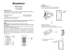
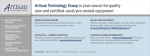
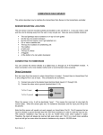
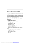
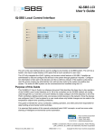
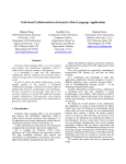
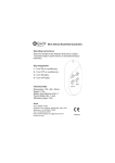
NovarNet
PC
NET
SD
RD
SD
RD
RI
CD
POWER
NovarNet® Interface
Module Setup Instructions
DOC. #560403000–B
11/23/04
PRINTED IN U.S.A.
Disclaimer
NovarNet® and iScope® are registered trademarks of Novar Controls Corporation.
Windows® is a registered trademark of Microsoft Corporation.
The material in this manual is for information purposes only. The contents and the product it
describes are subject to change without notice. Novar Controls Corporation makes no
representations or warranties with respect to this manual.
In no event shall Novar Controls Corporation be liable for technical or editorial omissions or mistakes
in this manual, nor shall it be liable for any damages, direct or incidental, arising out of or related to
the use of this manual.
Copyright © 2004 by Novar Controls Corporation. All rights reserved.
No part of this manual may be reproduced in any form or by any means
without prior written permission from Novar Controls Corporation.
Novar Controls Corporation
6060 Rockside Woods Blvd., Cleveland, OH 44131
Tel.: 800.348.1235
www.novarcontrols.com
NovarNet Interface Module Setup Instructions
Description
NovarNet® is a communication protocol developed by Novar Controls
Corporation that provides simultaneous peer-to-peer communications on a local
area network (LAN). This module allows multiple executive modules and
personal computers (PCs) running Novar Controls building management
software to be set up as nodes on the LAN to communicate and monitor the
remote system data and operating status.
In a NovarNet configuration, the executive modules are connected directly to the
LAN. PCs, which are set up in Novar Controls’ software as NovarNet
monitoring stations, must be connected to the network using a NovarNet
Interface Module.
This module features:
§
A 9-pin or 25-pin RS-232 port for connection to the PC.
§
An RS-485 port for connection to the LAN (through an executive module).
§
Configuration switches to set the address of the NovarNet monitoring station
and several other configuration functions.
§
Modem-style light-emitting diodes (LEDs) communication indicators.
§
Built-in LAN and PC communication capabilities.
Specifications
Power Requirements
Voltage:
Consumption:
24 VAC (transformer supplied)
20 VA
Operating Environment
Temperature:
Humidity:
32° to 140°F (0° to 60°C)
0 to 95% Relative, noncondensing
Physical Dimensions
Height:
Width:
Length:
Weight:
1.38 inches
4.88 inches
7 inches
0.63 lb
Precautions
Take the following precautions during installation:
DOC. #560403000–B
11/23/04
§
Observe all national and local electrical codes.
§
Use the Novar Controls–supplied transformer or an equivalent 24-VAC
transformer for power.
1
NovarNet Interface Module Setup Instructions
Setting Up the NovarNet
Interface Module
The NovarNet Interface Module is shipped with the following items:
§
A 9-pin RS-232 cable to be used to connect the module to a PC
A 25-pin cable adapter is also included to be used in place of a 9-pin port in
case the PC requires a 25-pin serial port.
§
A 24-VAC transformer
§
A green, screw-type wiring connector (Figure 1), which is already plugged
into the Network port on the back of the module. This connector can be
removed to make the wiring connections.
Plug-in Connector
for Wiring
NETWORK
COMM (-) COMM (+)
SHIELD
THIS DEVICE COMPLIES WITH PART 15 OF THE FCC RULES. OPERATION IS SUBJECT
TO THE FOLLOWING TWO CONDITIONS: 1) THIS DEVICE MAY NOT CAUSE HARMFUL
INTERFERENCE , AND 2) THIS DEVICE MUST ACCEPT ANY INTERFERENCE RECEIVED,
INCLUDING INTERFERENCE THAT MAY CAUSE UNDESIRED OPERATION.
PC
24VAC
ON 1 2 3 4
LABEL P/N 5705500
5
6
7
8
A0 A1 A2 A3 A4
RESERVED
6
CONT MODE
BAUD RATE
Connection to EP/2 Network
Connection to PC
Figure 1.
Power Transformer Connection
Configuration Switches
Rear panel of NovarNet Interface Module
Use the following procedures to connect the module to the PC and the executive
module and supply it with power.
Connecting to the PC
Use the following procedure to connect the module to a PC.
Step
Procedure
1
Connect the 9-pin cable supplied with the NovarNet Interface
Module to the PC port on the back of the module.
2
Tighten the screws to secure the cable to the module.
3
Connect the other end of the cable to an unused 9-pin serial port
on the PC
or
Connect the 25-pin adapter to the 9-pin cable and connect the
adapter to the PC’s serial port.
2
DOC. #560403000–B
11/23/04
NovarNet Interface Module Setup Instructions
Connecting to the Executive Module (Local Area Network)
Use a suitable shielded cable (Novar Controls WIR-1010, Belden 8761, or
equivalent) to make the connections to the executive module at the LAN terminals.
Step
1
Procedure
Connect the negative (–) wire to:
§
§
2
Connect the shield wire to:
§
§
3
EP/2: Terminal 23
Lingo: Terminal 28
EP/2: Terminal 24
Lingo: Terminal 29
Connect the positive (+) wire to:
§
§
EP/2: Terminal 25
Lingo: Terminal 30
Make the necessary network connections to the port labeled Network on the back
of the NovarNet Interface Module. If necessary, the connector can be removed
to make the connections.
Step
Procedure
1
Connect the negative (–) wire to the Comm negative (–) terminal.
2
Connect the shield wire to the Shield terminal.
3
Connect the positive (+) wire to the Comm positive (+) terminal.
Connecting Power
Use the transformer supplied with the module or an equivalent 24-VAC
transformer and make the following connections to supply power to the module.
Step
Procedure
1
Connect the 24-VAC transformer to the 24-VAC port on the
back of the module.
2
Plug the other end of the transformer into an available wall
socket.
§
When power is supplied, the Power LED on the front of the
module should light.
Setting the Address
The address switches are located on the back of the module (see Figure 1). The
first five switches are used to set the address of the NovarNet monitoring station
(the PC connected to the NovarNet Interface Module).
Refer to Figure 2 and set the first five switches to match the correct address of
the module (default is address 16).
DOC. #560403000–B
11/23/04
3
NovarNet Interface Module Setup Instructions
NOTE! The unit number in ESS32 is always one number higher
than the unit address. Also, although address 00 is shown
in Figure 2, a NovarNet Monitoring Station cannot use
address 00; an executive module must use that address.
ADDRESS
SWITCH
SETTINGS
ON
Figure 2.
ADDRESS
SWITCH
SETTINGS
ON
Address settings
Configuration switches 6, 7, and 8 are used for specific settings (Figure 3) related
to the operation of the NovarNet Interface Module with the PC and with
NovarNet.
Figure 3. Settings for Configuration Switches 6, 7, and 8
4
DOC. #560403000–B
11/23/04
NovarNet Interface Module Setup Instructions
§
Switch #6 is labeled “Reserved.” This switch relates to a NovarNet
communications timing operation that is dependent on the PROM level of the
executive module being used.
— For executive modules with PROM levels prior to version 18.00, set the
switch to on.
— For executive modules with PROM versions 18.00 or greater, set the
switch to off (the default).
§
Switch #7 refers to the communication baud rate between the NovarNet
Interface Module and the PC.
— Setting the switch to the on position sets the baud rate at 2400.
— Setting the switch to the off (default) position sets the baud rate at 9600.
In most applications, Novar Controls recommends keeping the baud rate at
9600 unless communication problems occur at this setting.
§
Switch #8 refers to NovarNet continuous mode. Continuous mode is only
functional when set at the node with the lowest address (typically 00) on a
LAN. This switch is not applicable to the NovarNet Interface Module because
a NovarNet monitoring station cannot be the lowest address on the network;
only an executive module can. It has been included for possible future
enhancements to NovarNet. Novar Controls recommends that this switch be
set at the default on position.
LED Communication
Indicators
Figure 4 shows the LED communication indicators on the front of the NovarNet
Interface Module.
NovarNet
PC
NET
SD
RD
SD
RD
RI
CD
POWER
Power Indicator
Sending Data (SD)
& Receiving Data (RD)
on the LAN
Figure 4.
DOC. #560403000–B
11/23/04
Carrier Dectect (CD)
Indicator
Ring Indicator (RI) to signal beginning
of alarms being reported to PC
Receiving Data (RD)
& Sending Data (SD)
with the PC
Front view of NovarNet Interface Module
§
As indicated previously, the Power LED lights when power is successfully
supplied to the module.
§
The send and receive data LEDs for the network side (the left SD and RD
LEDs) and the PC side (the right SD and RD LEDs) flash when data is
transmitted.
§
The ring indicator LED lights when an alarm session is beginning (the module
has a speaker that will also emit a sound each time the ring indicator LED
lights).
§
The carrier detect LED indicates that an online connection has been made
between the PC and the remote system.
5
NovarNet Interface Module Setup Instructions
Software Installation
Notes
The NovarNet Interface Module was designed for use with Novar Controls
Corporation’s iScope® and ESS32 software packages that run in the Windows ®
95/98/NT operating systems. When installing this software, select NovarNet
with the appropriate communication (Comm) port.
Refer to Novar Controls’ iScope® User’s Manual (Doc. No. 569041000) for
information about installing iScope. Refer to the Novar Controls Software
Installation Instructions (Doc. No. 569042000) for information about installing
ESS32. Both documents are available through any authorized Novar Technology
Center (NTC) or account representative.
Operating Notes
An advantage of the NovarNet Interface Module is that it can be left powered on
even if the PC to which it is connected is turned off. The module continues to
communicate with the LAN so that the network does not have to reconfigure
each time the PC is turned on and off.
If communication problems occur, all connections should be checked to make
sure they are secure.
Model and Part Numbers
Use the part numbers provided in Table 1 to order the necessary Novar Controls
parts.
Table 1. Novar Controls Part Numbers
PRODUCT
6
MODEL NO.
PART NO.
NovarNet Interface Module
NIM
734099000
Two-Conductor Shielded Cable
WIR-1010
709001000
ESS32/iScope Software Library CD )
ESS32/iScope
700199000
DOC. #560403000–B
11/23/04