1
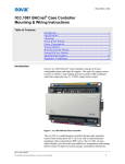
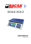
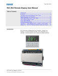
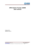
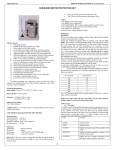
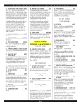
Artisan Technology Group is your source for quality
new and certified-used/pre-owned equipment
• FAST SHIPPING AND
DELIVERY
• TENS OF THOUSANDS OF
IN-STOCK ITEMS
• EQUIPMENT DEMOS
• HUNDREDS OF
MANUFACTURERS
SUPPORTED
• LEASING/MONTHLY
RENTALS
• ITAR CERTIFIED
SECURE ASSET SOLUTIONS
SERVICE CENTER REPAIRS
Experienced engineers and technicians on staff
at our full-service, in-house repair center
WE BUY USED EQUIPMENT
Sell your excess, underutilized, and idle used equipment
We also offer credit for buy-backs and trade-ins
www.artisantg.com/WeBuyEquipment
InstraView REMOTE INSPECTION
LOOKING FOR MORE INFORMATION?
Visit us on the web at www.artisantg.com for more
information on price quotations, drivers, technical
specifications, manuals, and documentation
SM
Remotely inspect equipment before purchasing with
our interactive website at www.instraview.com
Contact us: (888) 88-SOURCE | [email protected] | www.artisantg.com
A-201E SERIES
LINE REGENERATIVE
AC VARIABLE
FREQUENCY DRIVES
71/2 TO 75HP
Artisan Technology Group - Quality Instrumentation ... Guaranteed | (888) 88-SOURCE | www.artisantg.com
Built-in Power Supply Regeneration Function Makes
Mitsubishi Inverters even more Powerful.
The A201E Takes Inverter Performance to the Next Level
The high performance general purpose A200E series of inverters has just expanded with the addition of
a line regenerative version for demanding brake applications; the A201E.Advanced technologies have
been incorporated into a compact single unit to produce performance that is perfect for applications
such as elevators and line controls. It can improve performance while reducing the panel size for any
machinery that requires heavy duty braking such as elevators, centrifuges, testing equipment and
winders.
Artisan Technology Group - Quality Instrumentation ... Guaranteed | (888) 88-SOURCE | www.artisantg.com
Features
Comparison Chart (For 30 KW rating)
■ The inverter is integrated with a line regenerative
converter for a more compact unit.
Inverter + power supply
regenerative converter
Inverter with built-in power
supply regeneration
The area needed for installation is only 60-80% of conventional
models with stand-alone converters, for a big saving in required
panel space. Since the braking circuitry is built in, the troublesome chore of selecting a braking unit is eliminated.
■ Braking power dramatically increased
Enables 100% continuous regeneration and provides an ample
margin for overloads, handling 150% overloads for 60 seconds.
■ Packed with specialized functions
Operating functions ideal for elevator applications, such as stopping control and load detection high speed frequency control,
are standard.
■ Uses a multi-function, high-performance inverter
The inverter is based on the A200E which includes magnetic
flux vector control, auto-tuning, fast-response current restriction
and instant stop restarting. (See the user manual for details.)
(Units: mm/inch)
Comparative installation area: 100%
Comparative standard price: 100%
Braking power: 75% continuous, 150%
for 3 seconds
Main circuit wiring: 8 locations in the
inverter, 5 locations in the power supply
regenerative converter, 11 total lines
Comparative installation area: 72%
Comparative standard price: 96%
Braking power: 100% continuous, 150%
for 60 seconds
Main circuit wiring: 6 total I/Os
Line Regeneration
Power factor improvement reactor
Energy leakage during regeneration
A-201E
■ Total costs can be reduced
Costs are lower than conventional system combinations (inverter
power supply regenerative converters with power factor
improvement AC reactors). Since regenerative energy is returned
to the power supply, less heat is generated than in resistor braking systems and energy is used more efficiently.
AC reactor
Power
supply
IM
Regenerated
energy is
returned to the
power supply
here.
■ Full line-up
5.5K to 55K ratings are provided for both 200 V and 400 V classes.
Braking force is greatly increased by channeling regenerative energy back
from motor to power supply.
Certified under ISO9001.
R
R
Note: ISO9001 is a standard covering products, processes, and quality systems.
Artisan Technology Group - Quality Instrumentation ... Guaranteed | (888) 88-SOURCE | www.artisantg.com
Technical Overview
Machine Configurations
Applicable Motor Rating (KW)
200 V class
400 V class
5.5
FR-A221E-5.5K-UL
FR-A241E-5.5K-UL
7.5
FR-A221E-7.5K-UL
FR-A241E-7.5K-UL
11
FR-A221E-11K-UL
FR-A241E-11K-UL
15
FR-A221E-15K-UL
FR-A241E-15K-UL
18.5
FR-A221E-18.5K-UL
FR-A241E-18.5K-UL
22
FR-A221E-22K-UL
FR-A241E-22K-UL
30
FR-A221E-30K-UL
FR-A241E-30K-UL
37
FR-A221E-37K-UL
FR-A241E-37K-UL
45
FR-A221E-45K-UL
FR-A241E-45K-UL
55
FR-A221E-55K-UL
FR-A241E-55K-UL
FR - A221E - 5.5K - UL
Characteristics
7.5K11K 15K 22K
30K
37K 45K
55K
UL/C-UL Listed
Applicable Motor Rating
5.5K
~
Rating indicated in kW
55K
Symbol
Voltage Class
A221E
200V Class
A241E
400V Class
Symbol
Model
FR
FREQROL
Length of use td (sec)
500
Symbol
300
200
100
50
30
10
10
20
30
40
50
60
70
80
Short-term permissible regenerative power WRS (KW)
Sample applications
Elevator garages
Ceiling Crane
Trolley wire
Trolley wire
MC
NFB
Inverter with built-in power
supply regenerative function
B
Power supply
IM
Winding motor
IM
Programmable
controller
FRA201E
Operating
panel
Electromagnetic
brake
Operation
signals
Motor
DC reactor for
improving power
factor*
Running motor
Running motor
*
G
IM
Crane
IM
W
Circulating garage system
* Required when the power factor must be further improved.
Artisan Technology Group - Quality Instrumentation ... Guaranteed | (888) 88-SOURCE | www.artisantg.com
G
Wheel
Rail
External Dimension Drawings
(Units: mm)
(H4)
Two φC holes
Mounting leg (movable)
H1
H2
H
*
Location
where
parameter
unit is
installed
H3
C
D3
W2
W
D
200 V Class
D1
D2
400 V Class
250
300
390
450
470
600
234
284
370
430
450
580
190
220
290
350
370
480
470
600
600
700
700
900
425
540
535
635
630
830
FR-A241E-5.5/7.5K-UL
FR-A241E-11/15K-UL
FR-A241E-18.5/22K-UL
FR-A241E-30K-UL
FR-A241E-37/45K-UL
FR-A241E-55K-UL
250
300
390
450
470
600
234
284
370
430
450
580
190
220
290
350
370
480
470
600
600
700
700
900
454
575
575
675
670
870
8
10
10
10
15
15
425
540
535
635
630
830
454
575
575
675
670
870
8
10
10
10
15
15
8
15
15
15
15
15
D
270
294
320
340
368
405
8
15
15
15
15
15
H1 H2 H3 H4
W W1 W2 H
Inverter model
W1
H1 H2 H3 H4
W W1 W2 H
Inverter model
FR-A221E-5.5/7.5K-UL
FR-A221E-11/15K-UL
FR-A221E-18.5/22K-UL
FR-A221E-30K-UL
FR-A221E-37/45K-UL
FR-A221E-55K -UL
D
270
294
320
340
368
405
D1 D2 D3
C
2.3
3.2
3.2
3.2
3.2
3.2
10
10
12
12
14
14
170
169
190
195
205
215
100
125
130
145
163
190
D1 D2 D3
C
2.3
3.2
3.2
3.2
3.2
3.2
10
10
12
12
14
14
170
169
190
195
205
215
100
125
130
145
163
190
* Parameter unit is optional.
Panel Cut-out Dimensions
Modifications For a Smaller Enclosure
Enclosure
4 C screws
H3
H2
H5
Inside of
Enclosure
Inverter
When enclosing the inverter, placing the
heat sink fin so that it protrudes from the
casing, as shown in the figure at left, can
dramatically reduce the heat generated
within the casing.
Mitsubishi recommends these mounting
dimensions when designing more compact
fully sealed inverters, encased inverters,
and the like.
H4
Note: Remove the upper and lower mounting brackets
during installation so they can be moved. Follow the panel
cut-out dimensions below for the mounted sections.
W2
W3
(Units: mm)
Inverter model
W2
W3
H2
H3
H4
H5
C
Inverter model
W2
W3
H2
H3
H4
H5
C
FR-A221E-5.5/7.5K-UL
FR-A221E-11/15K-UL
FR-A221E-18.5/22K-UL
FR-A221E-30K-UL
FR-A221E-37/45K-UL
FR-A221E-55K-UL
190
220
290
350
370
480
240
290
376
436
456
586
454
575
575
675
670
870
434
548
546
646
641
841
12
17
17
17
17
17
8
10
12
12
12
12
M8
M8
M10
M10
M12
M12
FR-A241E-5.5/7.5K-UL
FR-A241E-11/15K-UL
FR-A241E-18.5/22K-UL
FR-A241E-30K-UL
FR-A241E-37/45K-UL
FR-A241E-55K-UL
190
220
260
350
370
480
240
290
346
436
456
586
454
575
575
675
670
870
434
548
546
646
641
841
12
17
17
17
17
17
8
10
12
12
12
12
M8
M8
M10
M10
M12
M12
Artisan Technology Group - Quality Instrumentation ... Guaranteed | (888) 88-SOURCE | www.artisantg.com
Specifications
Control specifications
Specifications
Control system
High carrier frequency sine-wave PWM control(select V/F control or magnetic flux vector control)
Output frequency range
0.2 to 400 Hz
Frequency
setting
resolution
Analog input
0.015 Hz/60 Hz (terminal input 2: 12 bit/0 to 10 V, 11 bit/0 to 5 V; terminal input 1: 12 bit/-10 to +10 V, 11 bit/-5 to
+5 V) 0.030 Hz/60 Hz
Digital input
0.002 Hz/60 Hz (when using PU: 0.01 Hz)
Frequency precision
For analog input: within ±0.2% of the maximum output frequency (25(°C ±10(°C). For digital input: within ±0.01%
of the set output frequency.
Voltage/frequency characteristics
Can be set anywhere with a base frequency of 0 to 400 Hz. Select constant torque or declining torque pattern.
Starting torque
150% 1 Hz (for magnetic flux vector control)
Torque boost
Manual and automatic torque boost
Acceleration/deceleration time
setting
0 to 3600 sec (set independently for acceleration and deceleration). Select between linear and S curve acceleration deceleration modes.
DC injection braking
Variable operating frequency (0 to 120 Hz), operating time (0 to 10 sec) and operating voltage (0 to 30%).
Stall prevention operating level
Analog input
Dislay
Input signal
Digital input
Set to BCD3 digit of 12 bit binary using the parameter unit (when using the optional FR-EPA or FR-EPE).
Select between independent forward and reverse or start signal self-holding input (3-wire input)
Multi-stage speed selection
Select up to 7 speeds (Each speed settable in 0 to 400 Hz range. Operating speed can be changed during operation using the parameter
unit.)
Second acceleration/deceleration
time selection
0 to 3600 sec (set independently for acceleration and deceleration).
Jogging operation selection
Terminal for selecting jogging (JOG) operating mode.*5
Current input selection
Select the input of a frequency setting signal DC 4 to 20 mA (terminal 4).
Output stop
Instant shut-off of inverter output (frequency and voltage)
Error reset
Clears holds after the protection function engages.
Upper and lower limit frequency settings, frequency jump operation, external thermal input selection, reversible polarity operation, instant stop
restart operation, commercial switching operation, forward/reverse prevention, slip compensation, operating mode selection, auto-tuning function, break sequence for elevators,*9 and load torque high-speed frequency control.*9
Operating status
Select 4 from among inverter operating, frequency reached, instant power stop (insufficient voltage), frequency detection, second frequency
detection, PU operating, overload alarm, and electronic thermal pre-alarm. Open collector output. Contact output: 1c contact (AC 230 V 0.3 A,
DC 30 V 0.3 A). Open collector: Alarm code (4 bit) output.
Error (inverter trip)
Contact output: 1c contact (AC 230 V 0.3 A, DC 30V 0.3 A). Open collector: Alarm code (4 bit) output.
For display meter
Select 1 from among output frequency, motor current (constant or peak value), output voltage, frequency setting, operating speed, motor
torque, converter output voltage (constant or peak value), electronic thermal load factor, input power, output power, load meter, and motor
excitation current. Pulse string output (1440 Hz/full-scale) or analog output (DC 0 to 10 V).
Display on parameter unit or main unit
LED
Addition display
possible only on
parameter unit
Operating status
Select from among output frequency, motor current (constant or peak value), output voltage, frequency setting, operating speed, motor
torque, overload, converter output voltage (constant or peak value), electronic thermal
load factor, input power, output power,*6 load meter, and cumulative running time.
Error
Display of error contents when protection function is engaged and storage of information of 8 errors.
Operating status
Presence of input terminal signal and status of output terminal signal.
Error
Output voltage, current, frequency, and I/O terminals status prior to engagement of protection function.
Interactive guidance
Protection and alarm function
Dislay
DC 0 to 5 V, 0 to 10 V, 0 to ± 5 V, 0 to ±10 V, 4 to 20 mA
Starting signal
Operation function
Output signal
Operating specifications
Frequency setting
signal
Settable operating current (0 to 200%); can be set whether to have a level or not.
Operations guide, trouble-shooting and graphic display for help function
Overcurrent breaking (acceleration, deceleration, constant speed), regenerative overvoltage breaking, insufficient voltage, instant stop, overload breaking (electronic thermal), ground overcurrent, output short, main circuit element overheating, stall prevention, overload warning, and
power supply regeneration circuit error.
Ambient temperature
–10°to +50°C (no freezing)
Ambient humidity
90% RH max. (no condensation)
Storage temperature*7
–20° to +65°C
Atmosphere
Indoor use. No corrosive gases, flammable gases, oil misting, or dust.
Altitude/vibration
1000 m above sea level max., 5.9 m/S2 {0.6 G max.} (based on JIS C 0911)
Notes
1 The rated output capacity shown is for an output voltage of 220 V for 200 V class and 440 V
for 400 V class.
2 The % value for overload current rating indicates the ratio to the inverter's rated output current.When using repeatedly, wait until the inverter and motor temperature fall below the temperature when at 100% load.
3 The maximum output voltage cannot go above the power supply voltage.The maximum output voltage can be set anywhere below the power supply voltage.
4 The power supply capacity varies with the value of the power supply impedance (including
input reactor and power lines).
5 Jogging operation is also possible with the parameter unit.
6 Shown as a positive value when running under power and a negative value during regeneration.
7 The temperature that can be applied for short times, such as in transit.
8 When the power supply voltage fluctuation with a 400 V class inverter is at or below 342 V or
at or above 484 V, a built-in transformer tap switch is required. See the manual for details.
9 See the manual for details
Artisan Technology Group - Quality Instrumentation ... Guaranteed | (888) 88-SOURCE | www.artisantg.com
Ratings
200 V class
Model
400 V Class
11K
15K
18.5K
22K
30K
37K
45K
55K
5.5K 7.5K
11K
15K
18.5K 22K
30K
37K
45K
55K
5.5
7.5
11
15
18.5
22
30
37
45
55
5.5
7.5
11
15
18.5
30
37
45
55
Rated capacity (kVA)*1
9.2
12.6
17.6
23.3
29
34
44
55
67
82
9.1
13
17.5
23.6
29
Rated current (A)
24
33
46
61
76
90
115
145
175
215
12
17
23
31
38
Output
5.5K 7.5K
Applicable Motor capacity (kw)
Overload current rating*2
Rated input AC voltage and frequency
Power supply
43
57
3 phase 200-220 V 50 Hz, 200-230 V 60 Hz
3 phase 380 to 460 V 50/60 Hz
100% continuous, 150% 60 sec
100% continuous, 150% 60 sec
3 phase 200-220 V 50 Hz, 200-230 V 60 Hz
3 phase 380-460 V 50/60 Hz
170-242 V 50 Hz, 170-253 V 60 Hz
323-506 V 50/60 Hz*8
±5%
±5%
Regenerative braking torque
Permissible fluctuation in AC voltage
32.8 43.4
Permissible fluctuation in frequency
54
65
84
71
86
110
150% 60 sec, 200% 0.5 sec (characteristics when outside limits)
150% 60 sec, 200% 0.5 sec (characteristics when outside limits)
Voltage *3
22
Amount of instantaneous voltage drop that can be
withstood
When operated at or above 165 V continuously and voltage falls from When operated at or above 320 V continuously and voltage falls from
rated voltage to under 165 V, 15 msec of
rated voltage to under 320 V, 15 msec of
continuous operation
continuous operation
Power supply facility capacity (kVA)*4
12
17
20
28
34
Approximate mass (kg (lb.))
23
(50.6)
52
66
80
100
12
17
20
28
34
41
52
Open type (IP00)
Open type (IP00)
Forced-air cooling
Forced-air cooling
Protective structure (JEM 1030)
Cooling system
41
23
34
32
52
(50.6)
(74.9)
(81.4)
(114.4)
52
63
(114.4) (138.6)
85
87
120
24
24
37
37
(187)
(191.4)
(264)
(52.8)
(52.8)
(81.5)
(81.5)
48
48
(105.6) (105.6)
66
80
100
63
85
85
120
(138.6)
(187)
(187)
(264)
Cautions
See the A200E Series catalog for information on cautions other than those listed below.
■ To Ensure Safe Use
• To ensure safe use, read the manual before using the product.
• This general-purpose inverter is not designed or manufactured to
be used in machinery and systems in situations where life may
depend on their operation. Contact the Mitsubishi customer liaison office before using this product in special applications such
as machinery or systems for automobiles, medical applications,
aerospace, nuclear power, electrical power, or undersea relays.
• Although this inverter was manufactured under strict quality control, safety devices should be installed if it is used in equipment in
which its failure may cause major damage or loss.
• Do not use it with loads other than 3-phase inductive motors.
• This product requires electrical work. Have all electrical work
done by an electrician.
■ Noise
During quiet operation, electromagnetic noise tends to increase, so
countermeasures should be taken. Depending on how the inverter
is installed, noise may have effects even when the carrier frequency is lowered.
Main Countermeasures
• The noise level can be reduced by lowering the carrier frequency.
• An FR-BIF(H) radio noise filter is effective at countering AM radio
noise.
• An FR-BSFO1 or FR-BLF line noise filter is effective at preventing
sensor malfunctions.
• Separate it at least 30 cm (at the very least 10 cm) from inductive
noise from inverter power wires and use twisted pair shielded
cable for signal lines.
■ Leaking Current
Electrostatic capacitance occurs between inverter I/O wiring and
other wiring, the ground and motors. Current can leak through any
of these. Its value can be affected by the carrier frequency and the
like, so in low noise operation leaking current increases and leaking power breakers and relays can operate at unwanted times.
Adopt the following counter measure to prevent this.
Countermeasure
• Lower inverter carrier frequency Pr.72. Motor noise, however, will
increase.
■ Power Supply Harmonics
A harmonic is defined as having a frequency that is an integer multiple of its basic frequency. Normally, frequencies up to 40 or 50
times (to several kHz) are defined as harmonics, while higher harmonics are treated as noise. The table below clarifies causes and
responses to noise and harmonics.
Item
Noise
Frequency band
Harmonic (10 kHz on up)
Harmonic
40 to 50 times (to several kHz)
Main cause
Inverter area
Converter area
Transmission route
Cable runs, space, induction
Cable runs
Effect
Distance, wiring route
Line impedance
Amount produced
Voltage change rate
Switching frequency
Current capacitance
Phenomenon
Misdetection of sensors, radio noise, etc.
Heat produced by condensive capacitors and generators
Remedy
Change wiring route
Install noise filter
Install reactor
■ Inverter Drives for 400 V Class Motors
When inverter drives are used on 400 V class motors, microsurge
voltages to the motor terminals can be produced, causing insulation breakdown.
(1) Strengthen motor insulation
Use a motor recommended by its manufacturer for use with
IGBT type variable frequency drives.
(2) Suppress microsurge voltages on the inverter side
Connect a filter on the inverter's secondary side to suppress
microsurge voltages that might create motor terminal voltages
of 850 V or below. When driving a Mitsubishi inverter, connect
the optional surge voltage suppression filter (FR-ASF-H) to the
inverter's secondary side.
Artisan Technology Group - Quality Instrumentation ... Guaranteed | (888) 88-SOURCE | www.artisantg.com
Sales Offices
CALIFORNIA - NORTH
1150 Bayhill Drive #301
San Bruno, CA 94066
Tel (415)873-0395
Fax (415)873-0397
CALIFORNIA - SOUTH
5665 Plaza Drive
Cypress, CA 90630
Tel (714)220-2500
Fax (714)229-3897
GEORGIA - SOUTH
3100 Avalon Ridge Place Ste 200
Norcross, GA 30071
Tel (770)613-5817
Fax (770)613-5849
GEORGIA - NATIONAL
3100 Avalon Ridge Place Ste 200
Norcross, GA 30071
Tel (770)613-5878
Fax (770)613-5849
ILLINOIS
500 Corporate Woods Parkway
Vernon Hills, IL 60061
Tel (847)478-2100
Fax (847)478-2253
INDIANA
599 Industrial Drive, Ste 102
Carmael, IN 46032
Tel (317)581-8999
Fax (317)581-8974
MASSACHUSETTS
410 Forest Street
Marlborough, MA 01752
Tel (508)303-0919
Fax (508)303-0694
MICHIGAN - EAST
46501 Commerce Center
Plymouth, MI 48170
Tel (313)453-6200
Fax (313)453-6211
PENNSYLVANIA
5 Great Valley Parkway #256
Malvern, PA 19355
Tel (610)648-3838
Fax (610)644-7048
MICHIGAN - WEST
1386 Baldwin Ave.
Jenison, MI 49428
Tel (616)457-8500
Fax (616)457-8578
TEXAS
9000 Royal Lane
Irving,TX 75063
Tel (972)929-0046
Fax (972)929-5396
MISSOURI
1802 Union Street #1 NW
St.Joseph, MO 64501
Tel (816)233-9797
Fax (816)233-6099
WASHINGTON
8000 N.E. Parkway Dr., Ste 300B
Vancouver,WA 98662
Tel (360)891-1661
Fax (360)891-1690
NEW JERSEY
800 Cottontail Lane
Somerset, NJ 08873
Tel (908)563-9889
Fax (908)563-9196
VIRGINIA
2025 E. Main Street - Suite 110
Richmond,VA 23223
Tel (804)644-1553
Fax (804)644-1556
NORTH CAROLINA
8307 University Executive Pk. Dr.
Charlotte, NC 28262
Tel (704)503-3500
Fax (704)503-3600
CANADA - ONTARIO
4299 14th Avenue
Markham, Ontario L3R 0J2
Tel (905)475-7728
Fax (905)475-7935
OHIO - NORTH
4807 Rockside Road Ste 400
Cleveland , OH 44145
Tel (216)642-8293
Fax (216)642-8294
OHIO - SOUTH
7566 Paragon Road
Centerville, OH 45459
Tel (937)291-4600
Fax (937)291-4606
Mitsubishi Electric Automation, Inc.
500 Corporate Woods Parkway,
Vernon Hills, Illinois 60061
Phone: (847) 478-2100
Fax (847) 478-0328
Mitsubishi Electric Sales Canada, Inc.
Industrial Automation Division
4299 14th Avenue
Markham, Ontario L3R OJ2
Phone: (905)475-7728
Fax: (905)475-7935
Artisan Technology Group - Quality Instrumentation ... Guaranteed | (888) 88-SOURCE | www.artisantg.com
Artisan Technology Group is your source for quality
new and certified-used/pre-owned equipment
• FAST SHIPPING AND
DELIVERY
• TENS OF THOUSANDS OF
IN-STOCK ITEMS
• EQUIPMENT DEMOS
• HUNDREDS OF
MANUFACTURERS
SUPPORTED
• LEASING/MONTHLY
RENTALS
• ITAR CERTIFIED
SECURE ASSET SOLUTIONS
SERVICE CENTER REPAIRS
Experienced engineers and technicians on staff
at our full-service, in-house repair center
WE BUY USED EQUIPMENT
Sell your excess, underutilized, and idle used equipment
We also offer credit for buy-backs and trade-ins
www.artisantg.com/WeBuyEquipment
InstraView REMOTE INSPECTION
LOOKING FOR MORE INFORMATION?
Visit us on the web at www.artisantg.com for more
information on price quotations, drivers, technical
specifications, manuals, and documentation
SM
Remotely inspect equipment before purchasing with
our interactive website at www.instraview.com
Contact us: (888) 88-SOURCE | [email protected] | www.artisantg.com