1
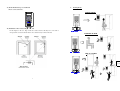
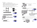
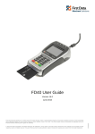
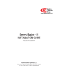
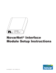
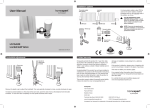
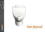
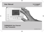
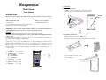
1.
Installation
1.1) Mounting of back-plate
a. Mark holes on the wall near the door with the back-plate.
Shed Alarm
b. Then use the screws provided to hang on the back-plate.
User Manual
INTRODUCTION
Mounting
The Response Shed Alarm is an intruder alarm and chime integrated system, designed to
Holes
protect your shed. It is a simple to use, easy to install unit.
Whats included in the pack :
1 x Shed Alarm
What you need to purchase :
1 x 9V PP3 Alkaline Battery
1 x Door/Window Contact Detector fitted with 5m cable
Fixing Kit (cable clips, screws and wall plugs)
IMPORTANT – Please read this manual carefully, in full, before commencing installation. You
will find installation easier if you follow these steps in the sequence shown.
SAFETY
Before proceeding with the installation, please note the following safety warnings:
DO NOT connect the mains supply directly to the products, this will cause permanent damage
to the products.
Control panel and Door/Window contact are for indoor use only. Avoid mounting location which can
expose the product to splashing or dripping liquid.
Always follow the manufacturer’s advice when using power tools and wear suitable protective
1.2) Installation of Main Unit
a. Make sure the Slide Switch is on OFF position.
b. Install the 9V battery into the battery compartment of the main unit
equipment (e.g. safety goggles) when drilling holes, etc. Before drilling holes in walls, check for
hidden electricity cables and water pipes. The use of a cable/pipe locator is advisable if in doubt.
.
Batteries should not be exposed to excessive heat such as sunshine, fire or the like; danger of
damage if battery is incorrectly replaced. Replace only with the same or equivalent type. (Do not
mix batteries type).
1.
2.
Installation
-------------P. 2-3
Working modes --------- P. 4-5
Door chime
Instant alarm
Delay alarm
3.
Panic alarm -------------P.6
4.
Change password -------P.6
5.
Alarm Hold -------------P.6
6.
Indications
c. Secure the Main Unit top case / PCB
onto the back-plate.
-------------P.7
1
2
1.3) Fix the Main Unit top case / PCB with
2.
Working Modes
the two screws at the base.
DOOR CHIME
1.4) Installation of Door Contact Magnetic Switch.
Fix the magnet on the door, align it with. the contact switch so that they are no more than 8
mm apart. The contacts should be fitted no more than 5m away from the man unit.
HOME OFF
OUT
INSTANT ALARM
HOME
OFF OUT
DELAY ALARM
Open door
20 seconds
HOME OFF OUT
3
4
How to operate
Use the slide switch to select HOME, OFF, and OUT mode.
3)
Panic Alarm
At HOME mode, the alarm will sound immediately when the door is opened.
Press Buttons “7” and “9” together, alarm will sound immediately.
(In case of emergency)
At OUT mode, when the door is opened, there is a 20 seconds delay before the alarm sounds.
The user may enter the PIN within the delay time to avoid the alarm being activated. (There is
+
7
a short Beep to indicate the exit delay is over and the system is armed)
9
At OFF mode, an entry chime (2 “Ding-Dong”) will sound when the door is opened.
The user may disable this Chime function by pulling out the “JUMPER”. (As shown on the
PCB diagram) (Factory default setting is with the “Chime” on)
4)
SW1
SW2
Change PIN Number
Red LED
User is highly recommended to change the PIN number when using it for the first time.
1)
BATT
Push the slide switch to “OFF” position.
SP1
2)
}Numbers
A)
0
T1
JP
Jumper
Slide Switch
U1
HOME
Key in the PIN numbers as follows:
1
OUT
4
3
Turn on Alarm System while Exiting the Shed
Current PIN
1) Push the slide switch to “OUT” position.
HOME
2) Close the door and leave the shed within 20 seconds.
B)
2
OFF
OFF
OUT
6
5
0
8
7
Switch off Alarm System when Entering the Shed
1) Enter your own four-digit PIN number within 20 seconds. (Note: The factory preset PIN no. is “1 2 3 4”. To
New PIN no.(e.g.5678)
change the PIN, please see procedure “4”)
3)
1
2
3
4
HOME
OFF
OUT
5)
If new PIN is accepted, a short beep sounds. If the command is rejected, a long beep sounds.
Alarm Hold
After Magnetic Switch was triggered and continued sounding for 1.5 minutes, the Alarm Hold
Light (Red
LED Indication) turns on. To turn off the Red LED Indication, do as follows
1)
2) Press Button “0”. Then wait for 5 seconds.
2) Push the slide switch to “OFF” position.
C)
Push the slide switch to “OFF” position.
HOME
When Inside the Shed
HOME
1) Push the slide switch to “HOME” position.
2) Magnetic Switch is activated to protect your shed
5
OFF
OUT
0
6
OFF
OUT
6.
Indications:
·Alarm hold indication – Red led blinks once every second.
·Low battery indication – Red led blinks once every 4 seconds.
– Red led blinks once
·Mode change
– No led on
·Normal condition
– One long beep
·Negative response
Note:
1. Pressing the valid four-digit PIN number can stop any alarm.
2. Red led blinks once per 4 seconds indicates that it is in low battery situation. Replace a new battery according to the
Installation section.
3. In case you forget the PIN number, take off the battery and replace it again after a couple of minutes. This restores the
PIN number to the factory default setting (1 2 3 4).
Disposal and Recycling
Batteries and waste electrical products should not be disposed of with household waste. Please recycle
where these facilities exist. Check with your local authority or retailer for recycling advice.
Guarantee
Novar ED&S undertakes to replace or repair at its discretion goods (excluding non rechargeable
batteries) should they become defective within 1 year solely as a result of faulty materials and
workmanship.
Understandably if the product has not been installed, operated or maintained in accordance with the
instructions, has not been used appropriately or if any attempt has been made to rectify, dismantle or
alter the product in any way the guarantee will be invalidated.
The guarantee states Novar ED&S entire liability. It does not extent to cover consequential loss or
damage or installation costs arising from the defective product. This guarantee does not in any way
affect the statutory or other rights of a consumer and applies to products installed within UK and
Eire only.
If an item develops a fault, the product must be returned to the point of sale with :
1. Proof of purchase.
2. A full description of the fault.
3. All relevant batteries (disconnected).
CUSTOMER HELPLINE
0844 736 9149
Most issues can be solved over the phone in a few minutes. Please contact our Helpline
Team on the above number for any installation and general advice regarding our products
Lines open 9.00 am to 5.00pm, Monday to Friday. Calls are charged at service providers
national rate.
Novar Electrical Devices and Systems.
The Arnold Centre, Paycocke Road, Basildon, Essex SS14 3EA.
7
50041720.REVA