1
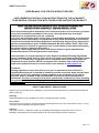
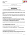
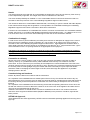
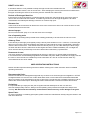
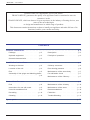
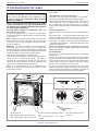
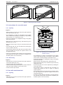
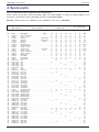
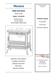
Belfort 2 19/09/2012 FR EN NL ES IT Multifuel stove Model : 134 04 11 Output : 4,5 kW DIN EN 13240 : 2005-10 Technical manual to be saved by the user for future reference Description of the appliance Installation instructions Parc d’activités de la Verte Rue Operating instructions Allée des Prêles 59270 BAILLEUL Spare parts Warranty certificate Tél. : 03 28 40 32 50 DRAFT 24 Jul 2013 USER MANUAL FOR STOVES WITHOUT BOILERS SUPPLEMENTARY INSTALLATION INSTRUCTIONS FOR THE UK MARKET TO BE READ IN CONJUNCTION WITH THOSE IN THE INSTRUCTION BOOKLET These instructions together with those in the instruction booklet cover the basic principles to ensure the satisfactory installation of the stove, although detail may need slight modification to suit particular local site conditions. In all cases the installation must comply with current Building Regulations, Local Authority Byelaws and other specifications or regulations as they affect the installation of the stove. It should be noted that the Building Regulations requirements may be met by adopting the relevant recommendations given in British Standards BS 8303, BS EN 15287-1:2007 as an alternative means to achieve an equivalent level of performance to that obtained following the guidance given in Approved Document J. Should any conflict apply between these instructions and the original manufacturers instructions then the most stringent advice must apply. Please note that it is a legal requirement under England and Wales Building Regulations that the installation of the stove is either carried out under Local Authority Building Control approval or is installed by a Competent Person registered with a Government approved Competent Persons Scheme. HETAS Ltd operate such a Scheme and a listing of their Registered Competent Persons can be found on their website at www.hetas.co.uk. CO Alarms:Building regulations require that when ever a new or replacement fixed solid fuel or wood/biomass appliance is installed in a dwelling a carbon monoxide alarm must be fitted in the same room as the appliance. Further guidance on the installation of the carbon monoxide alarm is available in BS EN 50292:2002 and from the alarm manufacturer’s instructions. Provision of an alarm must not be considered a substitute for either installing the appliance correctly or ensuring regular servicing and maintenance of the appliance and chimney system. HEALTH AND SAFETY PRECAUTIONS Special care must be taken when installing the stove such that the requirements of the Health and Safety at Work Act are met. Handling Adequate facilities must be available for loading, unloading and site handling. Fire Cement Some types of fire cement are caustic and should not be allowed to come into contact with the skin. In case of contact wash immediately with plenty of water. Asbestos This stove contains no asbestos. If there is a possibility of disturbing any asbestos in the course of installation then please seek specialist guidance and use appropriate protective equipment. Page 1 of 5 DRAFT 24 Jul 2013 Metal Parts When installing or servicing this stove care should be taken to avoid the possibility of personal injury. STOVE PERFORMANCE Refer to the manufacturer’s main instruction manual for details of the stove’s performance. PREPARATORY WORK AND SAFETY CHECKS IMPORTANT WARNING This stove must not be installed into a chimney that serves any other heating appliance. There must not be an extractor fan fitted in the same room as the stove as this can cause the stove to emit fumes into the room. Chimney In order for the stove to perform satisfactorily the chimney height must be sufficient to ensure an adequate draught of approximately 15 Pa so as to clear the products of combustion and prevent smoke problems into the room. NOTE: A chimney height of not less than 4.5 metres measured vertically from the outlet of the stove to the top of the chimney should be satisfactory. Alternatively the calculation procedure given in EN 13384-1 may be used as the basis for deciding whether a particular chimney design will provide sufficient draught. BS EN 15287-1:2007 gives additional details. The outlet from the chimney should be above the roof of the building in accordance with the provisions of Building Regulations Approved Document J. If installation is into an existing chimney then it must be sound and have no cracks or other faults which might allow fumes into the house. Older properties, especially, may have chimney faults or the cross section may be too large i.e. more than 230 mm x 230 mm. Remedial action should be taken, if required, seeking expert advice, if necessary. If it is found necessary to line the chimney then a flue liner suitable for solid fuel must be used in accordance with Building Regulations Approved Document J. Any existing chimney must be clear of obstruction and have been swept clean immediately before installation of the stove. If the stove is fitted in place of an open fire then the chimney should be swept one month after installation to clear any soot falls which may have occurred due to the difference in combustion between the stove and the open fire. If there is no existing chimney then any new system must be to the designation described above and in accordance with Building Regulations Approved Document J. A single wall metal fluepipe is suitable for connecting the stove to the chimney but is not suitable for use as the complete chimney. The chimney and connecting fluepipe must have a minimum diameter of 150 mm and its dimension should be not less than the size of the outlet socket of the stove. Any bend in the chimney or connecting fluepipe should not exceed 45. 90 bends should not be used. Combustible material should not be located where the heat dissipating through the walls of fireplaces or flues could ignite it. Therefore when installing the stove in the presence of combustible materials due account must be taken of the guidance on the separation of combustible material given in Building Regulations Approved Document J and also in these stove instructions. If it is found that there is excessive draught in the chimney then a draught stabiliser should be fitted. Fitting of a draught stabiliser will affect the requirement for the permanent air supply into the room in which the stove is fitted in accordance with Approved Document J (see also combustion air supply). Adequate provision e.g. easily accessible soot door or doors must be provided for sweeping the chimney and connecting fluepipe where it is not intended for the chimney to be swept through the appliance. Page 2 of 5 DRAFT 24 Jul 2013 Hearth The hearth should be level and able to accommodate the weight of the stove and its chimney if the chimney is not independently supported. The weight of the stove is indicated in the brochure. The stove should preferably be installed on a non-combustible hearth of a size and construction that is in accordance with the provisions of the current Building Regulations Approved Document J. The clearance distances to combustible material beneath, surrounding or upon the hearth and walls adjacent to the hearth should comply with the guidance on the separation of combustible material given in Building Regulations Approved Document J and also in these stove instructions. If the stove is to be installed on a combustible floor surface, it must be covered with a non-combustible material at least 12mm thick, in accordance with Building Regulations Approved Document J, to a distance of 30 cm in front of the stove and 15 cm to each side measuring from the door of the combustion chamber. Combustion air supply In order for the stove to perform efficiently and safely there must be an adequate air supply into the room in which the stove is installed to provide combustion air. The provision of air supply to the stove must be in accordance with current Building Regulations Approved Document J. Special attention should be taken in newer build properties where the design air permeability is less than 5m 3/h.m2. Approved Document J gives more information on this. An opening window is not appropriate for this purpose. The fitting of an external air kit direct to outside air must not be considered substitute for installing the appliance with a permanently open air vent in compliance with ventilation requirements stated in Approved Document J. Please reference ADJ for further guidance. Connection to chimney Stoves may have a choice of either a rear or top flue gas connector that allows connection to either a masonry chimney or a prefabricated factory made insulated metal chimney in accordance with their instructions. In some cases it may be necessary to fit an adaptor to increase the diameter of the flue to the minimum required 150 mm section of the chimney or liner. All joints in the connection between the stove and the chimney must be made gastight using fire cement and where necessary fire-proof rope infill. Means should be made for sweeping the entire length of the flue, be that through the appliance or by suitable sweeping hatch in the flue. Commissioning and handover Ensure all parts are fitted in accordance with the instructions. On completion of the installation allow a suitable period of time for any fire cement and mortar to dry out, before lighting the stove. Once the stove is under fire check all seals for soundness and check that the flue is functioning correctly and that all products of combustion are vented safely to atmosphere via the chimney terminal. On completion of the installation and commissioning ensure that the operating instructions for the stove are left with the customer. Ensure to advise the customer on the correct use of the appliance and warn them to use only the recommended fuel for the stove. Advise the user what to do should smoke or fumes be emitted from the stove. The customer should be warned to use a fireguard to BS 8423:2002 (Replaces BS 6539) in the presence of children, aged and/or infirm persons. HETAS Ltd Approval; These appliances have been approved by HETAS Ltd as an intermittent operating appliance for burning wood logs only. Page 3 of 5 DRAFT 24 Jul 2013 USER MANUAL FOR STOVES WITHOUT BOILERS SUPPLEMENTARY OPERATING INSTRUCTIONS FOR THE UK MARKET TO BE READ IN CONJUNCTION WITH THOSE IN THE INSTRUCTION BOOKLET WARNING NOTE Properly installed, operated and maintained this stove will not emit fumes into the dwelling. Occasional fumes from de-ashing and re-fuelling may occur. However, persistent fume emission is potentially dangerous and must not be tolerated. If fume emission does persist, then the following immediate action should be taken: (a) Open doors and windows to ventilate the room and then leave the premises. (b) Let the fire go out. (c) Check for flue or chimney blockage and clean if required (d) Do not attempt to relight the fire until the cause of the fume emission has been identified and corrected. If necessary seek expert advice. The most common cause of fume emission is flueway or chimney blockage. For your own safety these must be kept clean at all times. IMPORTANT NOTES General Before lighting the stove check with the installer that the installation work and commissioning checks described above have been carried out correctly and that the chimney has been swept clean, is sound and free from any obstructions. As part of the stoves’ commissioning and handover the installer should have shown you how to operate the stove correctly. CO Alarm Your installer should have fitted a CO alarm in the same room as the appliance. If the alarm sounds unexpectedly, follow the instructions given under “Warning Note” above. Air Controls Manually operated air control can be managed by adjusting the air control valve to increase/decrease the air flow to the stove. Use of fireguard When using the stove in situations where children, aged and/or infirm persons are present a fireguard must be used to prevent accidental contact with the stove. The fireguard should be manufactured in accordance with BS 8423:2002. Chimney cleaning The chimney should be swept at least twice a year. It is important that the flue connection and chimney are swept prior to lighting up after a prolonged shutdown period. If the stove is fitted in place of an open fire then the chimney will require sweeping after a month of continuous operation. This is a precaution to ensure that any “softer” deposits left from the open fire usage have not been loosened by the higher flue temperatures generated by the closed stove. Page 4 of 5 DRAFT 24 Jul 2013 In situations where it is not possible to sweep through the stove the installer will have provided alternative means, such as a soot door. After sweeping the chimney the stove flue outlet and the flue pipe connecting the stove to the chimney must be cleaned with a flue brush. Periods of Prolonged Non-Use If the stove is to be left unused for a prolonged period of time then it should be given a thorough clean to remove ash and unburned fuel residues. To enable a good flow of air through the appliance to reduce condensation and subsequent damage, leave the air controls fully open. Extractor fan There must not be an extractor fan fitted in the same room as the stove as this can cause the stove to emit smoke and fumes into the room. Aerosol sprays Do not use an aerosol spray on or near the stove when it is alight. Use of operating tools Always use the operating tools provided when handling parts likely to be hot when the stove is in use. Chimney Fires If the chimney is thoroughly and regularly swept, chimney fires should not occur. However, if a chimney fire does occur turn off the stove immediately and isolate the mains electricity supply (if applicable), and tightly close the doors of the stove. This should cause the chimney fire to go out. If the chimney fire does not go out when the above action is taken then the fire brigade should be called immediately. Do not relight the stove until the chimney and flueway have been cleaned and examined by a professional. Permanent air vent The stove requires a permanent and adequate air supply in order for it to operate safely and efficiently. In accordance with current Building Regulations the installer may have fitted a permanent air supply vent into the room in which the stove is installed to provide combustion air. This air vent should not under any circumstances be shut off or sealed. USER OPERATING INSTRUCTIONS Please read the important notices given above before referring to the main instruction book for detailed operating instructions. Recommended fuels: Please note that HETAS Ltd Appliance Approval only covers the use of wood logs on this appliance. HETAS Ltd Approval does not cover the use of other fuels either alone or mixed with the recommended fuels listed above, nor does it cover instructions for the use of other fuels. The stoves have a refuelling interval of 0.75h to achieve the nominal rated output. Wood logs should be seasoned with a moisture content of around 20%. De-Ashing: It is important that you empty the ash pan at regular intervals and dispose of ash in a safe and environmentally friendly manner. Always use the operating tools provided and replace the ashpit cover correctly. DO NOT allow ash to build up underneath the bed as this may cause damage to the grate. Spare Parts: For more information on obtaining spare parts, please contact the manufacturer directly using the contact in the main stove brochure. Page 5 of 5 “BELFORT” - ref. 134 04 11 FRANCO BELGE congratulates you on your choice. FRANCO BELGE, guarantees the quality of its appliances and is committed to meet its customers’ needs. FRANCO BELGE, which can boast a 80-year experience in the industry of heating devices, uses state-of-the-art technologies to design and manufacture its whole range of products. This document contains instructions on how to install your appliance and make full use of its functions, both for your comfort and safety. CONTENTS Product information . . . . . . . . . . . . . . . . . . . . . . . . . . . . . . . . . . . . . p. 3 Package . . . . . . . . . . . . . . . . . . p. 3 Description . . . . . . . . . . . . . . . . p. 3 Optional equipment. . . . . . . . . . . . p. 3 Principle of operation. . . . . . . . . . . p. 3 General characteristics. . . . . . . . . . p. 3 Installation instructions . . . . . . . . . . . . . . . . . . . . . . . . . . . . . . . . . . . p. 4 Warning to the user . . . . . . . . . . . p. 4 Chimney connector . . . . . . . . . . . . p. 6 Location of the unit . . . . . . . . . . . . p. 4 Door closing pressure . . . . . . . . . . p. 6 Flue . . . . . . . . . . . . . . . . . . . . p. 5 Maintenance of the stove body . . . . . p. 7 Assembly of flue spigot and blanking plates . . . . . . . . . . . . . . . . . . . . . . . p. 6 Pre-utilisation check . . . . . . . . . . . p. 7 Maintenance of the Chimney . . . . . . p. 7 Instructions for user . . . . . . . . . . . . . . . . . . . . . . . . . . . . . . . . . . . . . p. 8 Fuel . . . . . . . . . . . . . . . . . . . . p. 8 Maintenance of the chimney . . . . . . p. 10 Instructions for use with wood . . . . . . p. 9 Maintenance of the stove . . . . . . . . p. 10 Use with smokeless fuel . . . . . . . . . p. 9 Recommendations . . . . . . . . . . . p. 10 De-ashing . . . . . . . . . . . . . . . . p. 10 Firebricks . . . . . . . . . . . . . . . . p. 10 Cleaning . . . . . . . . . . . . . . . . . p. 10 Trouble Shooting . . . . . . . . . . . . p. 11 Spare parts . . . . . . . . . . . . . . . . . . . . . . . . . . . . . . . . . . . . . . . . . p. 12 2 Technical manual “1174” “BELFORT” - ref. 134 04 11 Product information This appliance is meant to burn wood or coal safely Warning An incorrectly installed wood stove can cause serious accidents. We recommend that you engage the services of a professional engineer for its installation and the regular maintenance requirements 1. Product information 1.1. Package - • 1 package : Stove complete. 1.2. Optional equipment Flue gas temperature . . . . . . . . °C Flue gas mass flow . . . . . . . . . g/s Efficiency . . . . . . . . . . . . . . . % Co (13% O2) . . . . . . . . . . . . . % Fuel rate . . . . . . . . . . . . . . kg/h 339 5,4 73,6 0,14 0,9 1.4. Description • Set of 4 long legs. Multifuel stove. In conformity with DIN EN 13240 : 2005-10. 1.3. General characteristics FUEL : WOOD Chimney draught required . . . . . . Pa Heated volume . . . . . . . . . . . . m3 Grate dimensions : - width . . . . . . . . . . . . . . . . mm - depth . . . . . . . . . . . . . . . . mm - usable height . . . . . . . . . . . . mm Max. log size - Length maxi . . . . . . . . . . . . . cm Ash pan capacity . . . . . . . . . . litres Net weight . . . . . . . . . . . . . . kg Flue gas temperature . . . . . . . . . °C - Nominal output . . . . . . . . . . . kW - Efficiency . . . . . . . . . . . . . . . % - Co (13% O2) . . . . . . . . . . . . . % - Flue gas mass flow . . . . . . . . . g/s - Fuel rate . . . . . . . . . . . . . . kg/h 12 130 270 200 240 25 3 77 290 4,5 74,3 0,36 5 1,5 FUEL : ANTHRACITE (SMOKELESS-FUEL) Tested with fuel brand name “phurnacite” entering in catégory A, table B2 from the standard EN 13240 - Nominal Heat Output . . . . . . . . kW 5,6 - Chimney draught required . . . . . Pa 12 • Intermittent-burning heating appliance. • Wood burnt on grate. • Wood and anthracite burning stove. • Close cast iron firebox. • Removable appliance, to be installed near a wall. • Detachable flue spigot for rear or top chimney connection. • Detachable top for easy handling and cleaning (rear smoke exit only). • Adjustable air controls for controlling the burning rate. • Spin wheel for lighting. • Large ash-pan. • Grate shaker control. 1.5. Principle of operation 340 420 Ø 139 Ø 125 550 131 The “ Belfort ” is designed for operation with the door closed. Heat is mainly diffused by radiation, through the window and body of the appliance. Combustion occurs on the grate, with draught entry through the top of the combustion chamber when using wood and under the grate when using smokeless fuels. 409 Figure 1 - Dimensions in mm Technical manual “1174” 3 “BELFORT” - ref. 134 04 11 Installation instructions 2. Installation instructions 2.1. Warning to the user An incorrectly installed heating appliance can cause serious accidents (chimney fires, burning of plastic insulation materials, in partition walls, etc.). This stove is exempted by DEFRA for burning wood logs in UK Smoke Control Areas (SCA). DEFRA exemption is dependent upon the appliance being fitted with a mechanical stop to prevent closure of the secondary air control beyond the 25% open position. You should check that this stop mechanism is fitted before installation of the stove and certainly before using the stove in a SCA to burn wood logs. If the stop mechanism is fitted then the minimum chimney flue diameter can be 125 mm but if the stop mechanism is not fitted then the stove is not exempted and the minimum chimney flue diameter is 150 mm in accordance with Approved Document J of the building regulations. The insulation of both the appliance and the exhaust gas pipe has to be reinforced and done according to the Standards and the Building Regulations for safety reasons. The installation must be carried out according to the Standards and the Building Regulations. Failure to respect the mounting instructions leads to engage the responsibility of the one doing the installation. The manufacturer’s responsibility shall be limited to the supply of the appliance. The installation of the appliance and the flue system must be in accordance with current Building Regulations. Failure to install the appliance with the Building Regulations will lead to the appliance warranty becoming in validated. material. Otherwise it must be necessary to install a non combustible protection. There must be a clearance of at least 350 mm at each side (back and sides) of the appliance in accordance with the below recommandations from a non combustible wall. This distance must be extended to a minimum clearance of 400 mm from any combustible material. If any part of the back or sides of the appliance lies within 350 mm horizontally of the wall, than the wall should be of solid non-combustible construction at least 75 mm thick from level to a level of 300 mm above the top of the appliance and 1200 mm above the hearth. Il however, any part or sides of the appliance lies within 50 mm of the wall, then the wall should be of solid non-combustible construction at least 200 mm thick from floor level to a level of 300 mm above the top of the appliance and 1200 mm above the hearth. Where the hearth itself in at least 150 mm from an adjacent wall. There is no requirement for protection of the wall. It should be noted that these thicknesses of solid non-combustible material can be substituted by thinner material if the same overall level of protection can be achieved. When using a single wall flue pipe, there must be a clearance (A) of at least three times its diameter (B) from any combustible materials. If the appliance has to be located in an opening, this distance must be extended to a minimum clearance (A) of 450 mm from the pipe or the stove body to any combustible materials. 2.2. Location of the unit Ventilation : For satisfactory appliance operation with a natural draught, check that sufficient air for combustion is available in the room. In houses equipped with one VMC (controlled mechanical ventilation), this one aspire and renew the ambient air; in this case, the residence is under slight low pressure and a non-sealable external air intake must be installed in addition to the chimney itself, at least 50 cm² in section. Position of the unit : For new installations, select a central position within the house, to provide a good heat distribution around the building. The heat distribution towards the other rooms will be made through the communicating doors. These 350 rooms must be at low pressure or fitted with non-adjustable air registers, placed so that they cannot be obstructed, to encourage circulation of the hot air. Floor and walls : make sure there are not combustible or covered with non combustible 4 300 350 Figure 2 - Clearances Technical manual “1174” “BELFORT” - ref. 134 04 11 Installation instructions Hearth : The appliance must stand on a fireproof hearth. It is possible to provide a hearth made of non combusible board/sheet material or tiles at least 12 mm thick (C). Constructional hearths should be constructed of solid non combustible material at least 125 mm thick (including the thickness of any non combustible floor under the hearth). The hearth must protrude at least 300 mm in front of the stove and 150 mm each side. Hearths are provided to prevent combustion appliances setting fire to the building fabric and furnishings and to limit the risk of people being accidentally burnt. Therefore, they should be separated from adjacent combustible materials and should be satisfactorily delineated from surrounding floor finishes (carpets etc.) as follows. Combustible material should not be placed under a constructional hearth for a solid fuel appliance within a vertical distance of 250 mm from the upper surface of the hearth, unless there is an airspace of at least 50 mm 1 3 2 Figure 3 - Removing the flue baffle the hearth. Where a superimposed hearth has been placed onto a constructional hearth, combustible material placed on or besid the constructional hearth should not extend under the superimposed hearth by more than 25 mm or closer to the appliance than 150 mm. Ensure that the hearth (superimposed or constructional) is suitably delineated to discourage combustible floor finishes from being laid too close to the appliance, by marking the edges or providing a change of level. Position the appliance on the hearth such that combustible marerial cannot be laid closer to the base of the appliance than : (a) At the front, 300 mm if the appliance is an open fire or stove which an, when opened , be operated as an open fire, or 225 mm in any other case. (b) At the back and sides, 300 mm or in accordance with the recommendations below which relate to distance from hearth to walls. Please refer to section J of the Building regulations. When using a single wall flue pipe, there must be a clearance (A) of at least 450 mm from any combustible materials (timber mantel, girder). Figure 4 - Smoke exit on the top Figure 5 - Smoke exit at rear Technical manual “1174” 5 “BELFORT” - ref. 134 04 11 Installation instructions Figure 6 Chimney connections 1 - Chimney 2 - Funnel-shape fireproof material 3 - Non combustible register plate 4 - Cleaning access door 5 - Liner 6 - Non combustible register plate and ventilated air 2.3. Flue The chimney must comply with Current Building Regulations. If in doubt, consult your Dealer or local Building Inspector. Existing flue : - The flue must be in good condition and must provide sufficient draught. - The flue must be suitable for the installation of solid fuel burning appliances and comply with Current Building Regulations. spigot (rep. 26, page 13) using the three bolts and washers supplied. - Check that the two blanking plates are fixed to the back wall (rep. 25 & 35, page 13). - Replace the internal baffle. - The flue must be clean. It should be swept to remove - Fix the sealing rope in the groove on the rear and fit soot and dislodge tar deposits. - The flue must be well insulated. If the flue inner wall surfaces are cold, a good thermal draw is impossible causing condensation problems (tar formation etc) to occur. - The flue must not be shared with other appliances. - The chimney must be at least 4.5 m (15 ft high). - In case of a flat roof or when the roof gradient is lower than 15°, the stack must be 1,2 m (4 feet) high at least. - If the chimney has any down draught tendency, due to its position in relation to nearby obstacles, then an anti-down draught cowl must be installed on the chimney or the chimney height must be increased. - If the decompression in the chimney is excessive, a draught stabiliser must be installed. Chimney to be built / new flue : - The flue must not be supported by the stove. - Consult a chimney specialist for advice on suitable flue systems for solid fuel appliances. 2.4. Assembly of flue spigot and blanking plates The stove is supplied with a connection flue spigot with an inner diameter of 125 mm or an outer diameter of 139 mm. - Remove the internal baffle (rep. 17, page 13). - Fit the sealing rope in the groove and attach the flue 6 - Remove the internal baffle (rep. 17, page 13) and the rear heat shield (rep. 16, page 13). the flue spigot, ensuring there is a good seal. - Fix the sealing rope in the groove on the top and fit the two blanking plates, ensuring there is a good seal. - Replace the internal baffle. - Remove the cut-out in the rear heat shield and re-fit. 2.5. Chimney connector The connection to flue must be carried out according to local building regulations. - The appliance must be installed as close as possible to the chimney. - Any connection pipe must be suitable for use with solid fuel burning appliances in accordance with Approved Document J of the building regulations. The connecting pipe must not reduce in diameter at any point to less than the diameter of the outlet of the stove. - The connection can be either vertical or horizontal. For horizontal connections, avoid right angle bends. - The join between the connection pipe and the stovepipe, and the flue, must be leak tight. - For the premises equipped with a mechanical controlled ventilation, the airtightness has to prevent the exhauster drawing out the smokes from the exhaust gas pipe. - The connection pipe and any draught stabiliser must have access for cleaning. - The spigot should be connected to a minimum of 125 mm flue system and in that case the appliance is capable of burning untreated wood and recommended solid fuels. Technical manual “1174” “BELFORT” - ref. 134 04 11 Installation instructions 2.6. Door closing pressure Figure 7 The closing latch rotates around a pressure screw positioned cam. - Loosen pressure screw 1. - Turn cam to desired position 2 . - Tighten pressure screw 1. The cast iron body panels of non-enamelled stoves can be cleaned with a proprietary stove cleaner or re-sprayed / touched up using a stove paint. These products are available from your Franco Belge Dealer. Caution ! : The appearance of cracks when burning the enamelled units is quite usual and tends to disappear when the appliance is cooling down. It should not be considered as a defect but rather as a patina of the enamel which does not affect its quality nor its service ability. 2.8. Pre-utilisation check 1 2 1 Screw 2 Cam Figure 7 - Door closing pressure 2.7. Maintenance of the stove body ‡The stove must be regularly cleaned. ‡Remove all deposits from the combustion chamber and clean the grate area. ‡The vitro ceramic glass can only be cleaned using a soft cloth and stove glass cleaner, available from your Franco Belge Dealer. DO NOT USE ABRASIVES ‡The vitro ceramic glass resists a temperature of 750°C. If the glass should be broken, it is recommended that only an original factory replacement should be fitted. For enamelled finishes, the stove body can be cleaned using a soft cloth either dry, or slightly damp with a very mild detergent. NEVER CLEAN ENAMEL SURFACES WHILST THE STOVE IS HOT. Technical manual “1174” Check the condition of the filler seals, that the door closes correctly. - Check that the glass is not damaged. - Check that the smoke passages are not obstructed by packaging or removable parts. - Check that the seals of the smoke-line are in good condition. - Check that the doors close correctly. - Check that all removable parts are correctly installed (fuel retainer (fig. 9), oscillating grate (fig. 10), baffle (fig. 3) etc... - Fit the ash tray, located in the ash pan, between the front legs (rep. 2, fig. 10). Note : if it acts of a ceramics braid, it is consumable and thus brought to be changed by the user. 2.9. Maintenance of the Chimney Very important ! In order to avoid any incident (chimney fire, etc...), maintenance tasks must be carried out regularly. If the appliance is regularly used, the chimney should be swept several times per year, together with the stovepipe connection section. If the chimney catches fire, you must cut off the flue draught, close the doors and windows, hatches and keys and call the Fire Brigade without delay. DO NOT OPEN THE DOOR OF THE APPLIANCE (OR AIR INLET) UNDER ANY CIRCUMSTANCES. 7 “BELFORT” - ref. 134 04 11 Instructions for user 3. Instructions for user The manufacturer will not be responsible for damages on parts of the appliance due to the use of prohibited fuel or due to an alteration of the appliance or its installation. Only use replacement parts supplied by the manufacturer. Don’t run the stove in mild weather with coal : Under certain circumstances (e.g. fog and repeated thaw) the chimney will not draw sufficiently well and thus be at the origin of asphyxia. Awaiting better weather circumstances, don’t use any coal but only wood. At the first lighting, the fire must be progressively increased to allow the various parts to expand normally and to dry up. Note : When the fire is lit for the first time, the stove may give off fumes from the new paint. This is normal but ensure the room is well ventilated during the first few hours of operation. Warning : properly installed and operated this appliance will not emit fumes into the dwelling. Occasional fumes from de-ashing and re-fuelling may occur. Persistent fume emission is dangerous and must not be tolerated. If fume emission does persist : Open doors and windows to ventilate room. Let the fire out and dispose of fuel from the appliance. Check for flue or chimney blockage, and clean if required. Do not attempt to relight the fire until the cause of the fume emission has been identified and corrected. If necessary seek expert advice. Note : It is recommended to use a fireguard in the presence of children, and also in the presence of old and/or infirm people. 3.1. Fuel This appliance is not an incinerator. Use hard wood logs, which have been cut for at least two years and stored, under a ventilated shelter. Use hardwood that have a higher calorific value per cu metre (Yoke-elm, oak, ash, maple, birch, elm, beech, etc.). Large logs must be split and cut to an useful length, before being stored in a sheltered and ventilated place. • Recommended fuel : The best fuels for use with the Franco Belge “Belfort” are : Seasoned wood. - hard wood logs that have been cut, split and stored for at least two years with a minimum moisture content of 20 % e.g. oak, beech, elm etc. Anthracite – dry steam coal fuels as described in type A – table B2 of the Standard – smokeless fuels along with coalite and anthracite. We do not recommend the use of Homefire on your stove due to the number of glass panels which have been effected by this fuel. • Prohibited fuel : Any form of housecoal (bituminous coal) or petroleum based fuels. We do not recommend that unseasoned wood (green wood) is used due to it’s high levels of moisture which will produce tar and in turn can cause the insides of the stove and the lining of the chimney to become coated which in turn could lead to a chimney fire. We do not recommend recovered wood e.g railway sleepers,chipboard, pallets are burned as these have been treated and will product a great deal of pollution to the environment and will overheat the appliance. B A B1 C B2 C1 C2 D E A : Door lock B : draught control (secondary air) B1 = flap opened B2 = flap closed C : Spin wheel for lighting (primary air) C1 = wheel opened C2 = wheel closed D : Grate shaker control E : Tool Figure 8 - Operating devices 8 Technical manual “1174” “BELFORT” - ref. 134 04 11 Instructions for user 1 2 1 2 Figure 9 - Removing the fuel retainer 3.2. Instructions for use with wood 1 3.2.1. Lighting Figure 8 • Slide the top air control (rep. B1) to the right. Open the lower spin wheel (rep. C1). • Lay firelighters or rolled up newspapers on the grate with a reasonable quantity, if necessary, of dry kindling wood. Place 2 or 3 small logs on top. • Light the newspaper or firelighters using a long taper and close the door. • When the fire is burning fiercely, add further logs of a diameter up to 10 cm. 2 • When the stove body is very hot, close the lower spin wheel. • The burning rate can now be lowered by moving the top air control to the left. • The airwash system works with the top airslide. When the top airslide is full open the system works at its strongest efficiency. 1 Oscillating grate 2 Ash tray • The more closed down the airslide is, the less effective Figure 10 - Mounting the oscillating grate and the ash tray the airwash will be (when shut down completely, the airwash system can not function). - Lay firelighters or rolled up newspapers on the grate 3.2.2. Re-fuelling Figure 8 - Slide the top air control (rep. B1) to the right. Open the lower spin wheel (rep. C1). - Open the glass door and add logs. - Leave the lower spin wheel open for a few minutes to allow the initial volatiles in the wood to burn. - Close the lower spin wheel. 3.3. Use with smokeless fuel 3.3.1. Lighting Figure 8 - Slide the top air control (rep. B1) to the right. Open the lower spin wheel. Technical manual “1174” with a reasonable quantity, if necessary, of dry kindling wood. Place a small quantity of solid fuel on top. - Light the newspaper or firelighters using a long taper and close the door. - When the fire is burning fiercely, add further fuel. - When the stove body is hot, close the top air control by sliding to the left. - The burning rate can now be adjusted by rotating the lower spin wheel. - The nominal output is achieved with secondary air closed and primary air (rep. C, figure 8, page 8) opened at 50 %. - The airwash system works with the top airslide. When the top airslide is full open the system works at its strongest efficiency. - The more closed down the airslide is, the less effective the airwash will be (when shut down completely, the airwash system can not function). 9 “BELFORT” - ref. 134 04 11 Instructions for user 3.3.2. Re-fuelling 3.7. Maintenance of the stove - Open the lower spin wheel. - Open the glass door and add fuel. - Leave the lower spin wheel open for a few minutes to • The appliance must be cleaned regularly, together with allow the initial volatiles in the fuel to burn. - Adjust the lower spin wheel to the desired position. 3.4. De-ashing the connecting pipe and the flue pipe. • Remove all deposits from the combustion chamber and clean the grate area. • The glass can be cleaned using a soft cloth dampened with a mix of water and vinegar or a specialist stove glass cleaning solution (obtainable from your local stockist). • It is vital that the ashpan is regularly emptied. • If the ashes are allowed to build up in the ashpan, • This must only be done when the appliance is cold, Do these will “sandwich” the grate between two layers of ash and will cause damage and premature wear to the grate. • The vitro ceramic glass resists a temperature of 750°C. • It is best to empty the ashpan when the appliance is • Check that there are no obstructions before relighting cold. • Always remove the ashpan with the tool supplied. • Dispose of the ashes carefully - there may still be hot embers within the ashes. 3.5. Cleaning It is essential to keep the grate free from a heavy build up of ashes. The Belfort is equipped with a grate riddling device which is used to “shake” ashes off the grate into the ash pan. Whenever the stove is burning without life when the lower spin wheel is open, use the riddling lever to clear the grate of surplus ashes. REMEMBER TO BURN SOLID FUEL CORRECTLY, AlR SHOULD BE ALLOWED TO FLOW FROM THE ASH PIT AREA THROUGH THE GRATE AND THROUGH THE FUEL. IF THE GRATE OR ASH PAN ARE CONGESTED, THE PERFOMANCE WILL BE EFFECTED. If burning solid fuel, always empty the ash pan at least once a day or whenever it is full of ashes. Never allow the ashpan to overfill allowing ash to be in contact with the underside of the grate. If this condition is allowed, the grate will wear out pre-maturely. 3.6. Maintenance of the chimney Very important ! In order to avoid any incident (chimney fire, etc...), maintenance tasks must be carried out regularly. If the appliance is regularly used, the chimney should be swept several times per year, together with the stovepipe connection section. If the chimney catches fire, you must cut off the flue draught, close the doors and windows, hatches and keys and call the Fire Brigade without delay. not use abrasive cleaners. If the glass should be broken, it is recommended that only an original factory replacement should be fitted. after a long period of disuse. • The appliance must not be used with a flue serving several appliances. • The baffle plates should be removed regularly and any ash or deposits cleaned away. • Ashes must not be allowed to build up. • The door rope seals should be checked annually and replaced when required. • The grates must be free from any obstructions always ensure there are no pieces of dislodged fuel or embers in between the grate castings. For enamelled finishes, the stove body can be cleaned using a soft cloth either dry, or slightly damp with a very mild detergent. NEVER CLEAN ENAMEL SURFACES WHILST THE STOVE IS HOT. The cast iron body panels of non-enamelled stoves can be cleaned with a proprietary stove cleaner or re-sprayed / touched up using a stove paint. These products are available from your Franco Belge Dealer. 3.8. Recommendations This room heater is a high heat producing appliance and may cause severe burns if touched on the glass front door, or on top directly over the burner. KEEP CHILDREN AWAY. The stove may still be hot even when fire has burnt out. DO NOT OPEN THE DOOR OF THE APPLIANCE (OR AIR INLET) UNDER ANY CIRCUMSTANCES. Chimney condition should be checked at least once per year by a professional engineer. 10 3.9. Firebricks When replacing firebricks, the fire must be progressively increased to allow the firebricks to expand normally and to dry up. Technical manual “1174” “BELFORT” - ref. 134 04 11 Instructions for user 3.10. Trouble Shooting þ : This sign means that you should ask for a qualified engineer to do the work. Problem Probable causes - Action Fire difficult to start Fire goes out Wood green, too damp or poor quality. - Use the recommended fuel. Logs are too big. - To light the fire, use small, very dry twigs. To maintain Air starvation. - Open lower air control (coal) or top air control (wood). the fire, use split logs. Insufficient draught. þ - Check that the flue is not obstructed, sweep it if necessary - Seek advice from a chimney specialist. Fire burns too quickly. Too much draught. - Ensure that the lower air control is closed (with wood burning) - Partially close the top air control lever. Excessive draught. þ Poor quality wood. - Install a draught stabiliser. Consult your Dealer. - Do not continuously burn small wood, sticks, bundles, carpentry offcuts (plywood, pallets), etc. Smokes when lighting up. Flue duct is cold. - Burn paper and kindling wood to increase heat. Room is in decompression. - In houses equipped with mechanical ventilation, partly open a window until the fire is well established. Smokes while burning. Draught is insufficient. þ - Consult a chimney specialist. - Check that the flue is not obstructed, sweep if necessary. Down draught. þ - Install an anti-down draught cowl. Consult your Dealer. Room is in decompression. þ - In houses equipped with Mechanical Ventilation, an outside air intake must be installed for the chimney. Low heat output. Technical manual “1174” Incorrect Fuels. - Use the recommended fuel. 11 “BELFORT” - ref. 134 04 11 Spare parts 4. Spare parts Only use replacement parts supplied by the manufacturer. When ordering spare parts, specify the stove type and serial number, including the colour index (on the guarantee or identification plate), the name of the part and the part number. Example : Belfort wood stove : “Belfort”, model : 134 04 11, colour Y, top : 352136 EF. A = 1340411 Y B = 1340411 J N° Code 1 2 3 4 5 7 8 9 10 11 13 14 15 16 17 18 19 20 20 20 20 20 20 21 22 22 22 22 22 22 22 23 23 23 23 23 23 24 25 25 25 25 25 25 26 26 26 26 26 26 27 28 29 29 29 29 29 29 30 30 30 100917 105123 105261 105262 110404 134258 181632 163196 166003 181614 181615 188798 189103 205368 222542 259015 262321 300118 300118 300118 300118 300118 300118 300477 301526 301526 301526 301526 301526 301526 301526 301742 301742 301742 301742 301742 301742 301901 303718 303718 303718 303718 303718 303718 303860 303860 303860 303860 303860 303860 306268 307432 309870 309870 309870 309870 309870 309870 309989 309989 309989 12 C = 1340411 C D = 1340411 I E = 1340411 D F = 1340411 P G = 1340411 E . . . Description . . . . . . . . . . . . . Type . . . . A . . . B . . . C . . . D . . . E . . . F . . . G . . Qty . . . . . . . . . . . . . . . . . . . . . . . . . . . . . . . . . . 79. EF MK MP RH RP . . 66. 79. EF MK MP RH RP 79. EF MK MP RH RP . . 79. EF MK MP RH RP 79. EF MK MP RH RP . . . . 79. EF MK MP RH RP 66. 79. EF . . . . . . . . . . . . . . . . . . . . . . . . . . . . . . . . . . . . . . . . . . . . . . . . . . . . . . . . . . . . . Cam pin12x20 M7 . . . . . . . . . . . . . . . . . A . . . B . . . C . . . D . . . E Knob . 191B. . . . . . . . . . . . . . . . . . . . A . . . B . . . C . . . D . . . E Firebrick . . . . . . . . . . . . . 328X70X35 . . A . . . B . . . C . . . D . . . E Firebrick . . . . . . . . . . . . . 207X207X35 . . A . . . B . . . C . . . D . . . E Hinge pin . . . . . . . . . . . . . . 6X30 . . . . A . . . B . . . C . . . D . . . E Bushing . . . . . . . . . . . . . . . . . . . . . . . A . . . B . . . C . . . D . . . E Adhesive rope . . . . . . . . . . . . . . . . . . . A . . . B . . . C . . . D . . . E Descriptive plate . . . . . . . . . . . . . . . . . . A . . . B . . . C . . . D . . . E Spring. 11x15 . . . . . . . . . . . . . . . . . . . A . . . B . . . C . . . D . . . E Ceramic rope . . . . . . . . . . . Ø 9,5mm . . . A . . . B . . . C . . . D . . . E Ceramic rope . . . . . . . . . . . . Ø 12 . . . . A . . . B . . . C . . . D . . . E Glass . 267X205. . . . . . . . . . . . . . . . . . A . . . B . . . C . . . D . . . E Screw . 27x8x6 . . . . . . . . . . . . . . . . . . A . . . B . . . C . . . D . . . E Back panel . . . . . . . . . . . . . . . . . . . . . A . . . B . . . C . . . D . . . E Flue baffle . . . . . . . . . . . . . . . . . . . . . A . . . B . . . C . . . D . . . E Fixing plate . . . . . . . . . . . . . . . . . . . . . A . . . B . . . C . . . D . . . E Heat shield . . . . . . . . . . . . . . . . . . . . . . . . . B . . . C . . . D . . . . Leg . . . . . . . . . . . . . . . . . . . . . . . . . . . . . B . . . . . . . . . . . . . Leg . . . . . . . . . . . . . . . . . . . . . . . . . A . . . . . . . . . . . . . . . . E Leg. . . . . . . . . . . . . . . . . . . . . . . . . . . . . . . . . . C . . . . . . . . . Leg . . . . . . . . . . . . . . . . . . . . . . . . . . . . . . . . . . . . . . D . . . . Leg . . . . . . . . . . . . . . . . . . . . . . . . . . . . . . . . . . . . . . . . . . . Leg. . . . . . . . . . . . . . . . . . . . . . . . . . . . . . . . . . . . . . . . . . . . Base . . . . . . . . . . . . . . . . . . . . . . . . A . . . B . . . C . . . D . . . E Door lock . . . . . . . . . . . . . . . . . . . . . . . . . . . . . . . . . . . . . . . E Door lock . . . . . . . . . . . . . . . . . . . . . . . . . . B . . . . . . . . . . . . . Door lock . . . . . . . . . . . . . . . . . . . . . . A . . . . . . . . . . . . . . . . . Door lock . . . . . . . . . . . . . . . . . . . . . . . . . . . . . . C . . . . . . . . . Door lock . . . . . . . . . . . . . . . . . . . . . . . . . . . . . . . . . . . D . . . . Door lock . . . . . . . . . . . . . . . . . . . . . . . . . . . . . . . . . . . . . . . . Door lock . . . . . . . . . . . . . . . . . . . . . . . . . . . . . . . . . . . . . . . . Air damper . . . . . . . . . . . . . . . . . . . . . . . . . B . . . . . . . . . . . . . Air damper . . . . . . . . . . . . . . . . . . . . . A . . . . . . . . . . . . . . . . E Air damper. . . . . . . . . . . . . . . . . . . . . . . . . . . . . . C . . . . . . . . . Air damper . . . . . . . . . . . . . . . . . . . . . . . . . . . . . . . . . . D . . . . Air damper . . . . . . . . . . . . . . . . . . . . . . . . . . . . . . . . . . . . . . . Air damper. . . . . . . . . . . . . . . . . . . . . . . . . . . . . . . . . . . . . . . . Oscillating grate . . . . . . . . . . . . . . . . . . A . . . B . . . C . . . D . . . E Blanking plate. . . . . . . . . . . . . . . . . . . . . . . . B . . . . . . . . . . . . . Blanking plate . . . . . . . . . . . . . . . . . . . A . . . . . . . . . . . . . . . . E Blanking plate . . . . . . . . . . . . . . . . . . . . . . . . . . . . C . . . . . . . . . Blanking plate . . . . . . . . . . . . . . . . . . . . . . . . . . . . . . . . D . . . . Blanking plate . . . . . . . . . . . . . . . . . . . . . . . . . . . . . . . . . . . . . . Blanking plate . . . . . . . . . . . . . . . . . . . . . . . . . . . . . . . . . . . . . . Flue collar . . . . . . . . . . . . . . . . . . . . . . . . . . B . . . . . . . . . . . . . Flue collar . . . . . . . . . . . . . . . . . . . . . A . . . . . . . . . . . . . . . . E Flue collar . . . . . . . . . . . . . . . . . . . . . . . . . . . . . . C . . . . . . . . . Flue collar . . . . . . . . . . . . . . . . . . . . . . . . . . . . . . . . . . D . . . . Flue collar . . . . . . . . . . . . . . . . . . . . . . . . . . . . . . . . . . . . . . . . Flue collar . . . . . . . . . . . . . . . . . . . . . . . . . . . . . . . . . . . . . . . . Back wall . . . . . . . . . . . . . . . . . . . . . . A . . . B . . . C . . . D . . . E Fuel retainer . . . . . . . . . . . . . . . . . . . . A . . . B . . . C . . . D . . . E Front plate . . . . . . . . . . . . . . . . . . . . . . . . . B . . . . . . . . . . . . . Front plate . . . . . . . . . . . . . . . . . . . . . A . . . . . . . . . . . . . . . . E Front plate . . . . . . . . . . . . . . . . . . . . . . . . . . . . . . C . . . . . . . . . Front plate . . . . . . . . . . . . . . . . . . . . . . . . . . . . . . . . . . D . . . . Front plate . . . . . . . . . . . . . . . . . . . . . . . . . . . . . . . . . . . . . . . Front plate . . . . . . . . . . . . . . . . . . . . . . . . . . . . . . . . . . . . . . . . Main door . . . . . . . . . . . . . . . . . . . . . . . . . . . . . . . . . . . . . . . E Main door . . . . . . . . . . . . . . . . . . . . . . . . . . B . . . . . . . . . . . . . Main door . . . . . . . . . . . . . . . . . . . . . . A . . . . . . . . . . . . . . . . . . . . . . . . . . . . . . . . . . . . . . . . . . . . . . . . . . . . . . . . . . . . . . . . . . . . . . . . . . . . . . . . . . . . . . . . . . . . . . . . . . . . . . . . . . . . . . . . . . . . . . . . . . . . . . . . . . . . . . . . . . . . . . . . . . . . . . . . . . . . . . . . . . . . . . . . . . . . . . . . . . . . . . . . . . . . . . . . . . . . . . . . F F F F F F F F F F F F F F F F F . . . . F . F . . . . . F . . . . . F . F . . . . F . . . . . F . F F . . . . F . . . . . . . . . . . . . . . . . . . . . . . . . . . . . . . . . . . . . . . . . . . . . . . . . . . . . . . . . . . . . . . . . . . . . . . . . . . . . . . . . . . . . . . . . . . . . . . . . . . . . . . . . . . . . . . . . . . . . . . . . . . . . . . . . . . . . . . . . . . . . . . . . . . . . . . . . . . . . . . . . . . . . . . . . . . . . . . . . . . . . . . . . . . G. G. G. G. G. G. G G. G. G G G. G. G. G. G. G. . . . . . . . . . . G. G. . . . . . . . . . . . . G. . . . . . . . . . . G. G. . . . . . . . . . . G. . . . . . . . . . . G. G. G. . . . . . . . . . . G. . . . . . . . . . . . . . . . . . . . . . . . . . . . . . . . . . . . . . . . . . . . . . . . . . . . . . . . . . . . . . . . . . . . . 01 . 01 . 01 . 02 . 02 . 01 0,90 m . 01 . 01 1,92 m 1,35 m . 01 . 01 . 01 . 01 . 04 . 01 . 04 . 04 . 04 . 04 . 04 . 04 . 01 . 01 . 01 . 01 . 01 . 01 . 01 . 01 . 01 . 01 . 01 . 01 . 01 . 01 . 01 . 01 . 01 . 01 . 01 . 01 . 01 . 01 . 01 . 01 . 01 . 01 . 01 . 01 . 01 . 01 . 01 . 01 . 01 . 01 . 01 . 01 . 01 . 01 Technical manual “1174” “BELFORT” - ref. 134 04 11 Spare parts ! $ $ ' " $ ! % " ! ! # " " ! ' " # " ! " ! ! " % % & " & & ! # ! & ! ' % ! " # # ! # ! ' ! & ! $ " " % " " " " Figure 11 - Stove - explosed view Technical manual “1174” 13 “BELFORT” - ref. 134 04 11 A = 1340411 Y B = 1340411 J N° Code 30 30 30 30 31 31 31 31 31 31 32 32 32 32 32 32 33 34 35 36 36 36 36 36 36 37 37 37 37 37 37 38 39 40 41 42 43 44 44 44 44 45 45 45 45 45 45 45 46 47 48 309989 309989 309989 309989 310724 310724 310724 310724 310724 310724 310822 310822 310822 310822 310822 310822 315603 319731 327801 327902 327902 327902 327902 327902 327902 352136 352136 352136 352136 352136 352136 237423 458404 624040 613302 808001 325304 161027 161048 161032 161039 988839 988841 988882 988843 988889 988897 988840 181607 300122 142881 14 Spare parts C = 1340411 C D = 1340411 I E = 1340411 D F = 1340411 P G = 1340411 E . . . Description . . . . . . . . . . . . . Type . . . . A . . . B . . . C . . . D . . . E . . . F . . . G . . Qty MK MP RH RP 79. EF MK MP RH RP 79. EF MK MP RH RP . . . . . . 79. EF MK MP RH RP 79. EF MK MP RH RP . . . . . . 60. ED . . . . . . . . . . . . . . . . . . . . . . . . . . . . . . . . . . . . . . . . . . . . . . . . . . . . . . . . . . . . . . . . . . . . . . . . . . . . . . . . . Main door . . . . . . . . . . . . . . . . . . . . . . . . . . . . . . C . . . . . . . . . Main door . . . . . . . . . . . . . . . . . . . . . . . . . . . . . . . . . . D . . . . Main door . . . . . . . . . . . . . . . . . . . . . . . . . . . . . . . . . . . . . . . . Main door . . . . . . . . . . . . . . . . . . . . . . . . . . . . . . . . . . . . . . . . R. side panel . . . . . . . . . . . . . . . . . . . . . . . . B . . . . . . . . . . . . . R. side panel . . . . . . . . . . . . . . . . . . . . A . . . . . . . . . . . . . . . . E R. side panel . . . . . . . . . . . . . . . . . . . . . . . . . . . . C . . . . . . . . . R. side panel . . . . . . . . . . . . . . . . . . . . . . . . . . . . . . . . . D . . . . R. side panel . . . . . . . . . . . . . . . . . . . . . . . . . . . . . . . . . . . . . . R. side panel . . . . . . . . . . . . . . . . . . . . . . . . . . . . . . . . . . . . . . L. side panel . . . . . . . . . . . . . . . . . . . . . . . . B . . . . . . . . . . . . . L. side panel . . . . . . . . . . . . . . . . . . . . A . . . . . . . . . . . . . . . . E L. side panel. . . . . . . . . . . . . . . . . . . . . . . . . . . . . C . . . . . . . . . L. side panel . . . . . . . . . . . . . . . . . . . . . . . . . . . . . . . . . D . . . . L. side panel . . . . . . . . . . . . . . . . . . . . . . . . . . . . . . . . . . . . . . L. side panel. . . . . . . . . . . . . . . . . . . . . . . . . . . . . . . . . . . . . . . Air duct . . . . . . . . . . . . . . . . . . . . . . . A . . . B . . . C . . . D . . . E Grate support. . . . . . . . . . . . . . . . . . . . A . . . B . . . C . . . D . . . E Clamp. . . . . . . . . . . . . . . . . . . . . . . . A . . . B . . . C . . . D . . . E Ash-tray . . . . . . . . . . . . . . . . . . . . . . . . . . . B . . . . . . . . . . . . . Ash-tray. . . . . . . . . . . . . . . . . . . . . . . A . . . . . . . . . . . . . . . . E Ash-tray . . . . . . . . . . . . . . . . . . . . . . . . . . . . . . . C . . . . . . . . . Ash-tray . . . . . . . . . . . . . . . . . . . . . . . . . . . . . . . . . . . D . . . . Ash-tray . . . . . . . . . . . . . . . . . . . . . . . . . . . . . . . . . . . . . . . . . Ash-tray . . . . . . . . . . . . . . . . . . . . . . . . . . . . . . . . . . . . . . . . . Top plate . . . . . . . . . . . . . . . . . . . . . . . . . . B . . . . . . . . . . . . . Top plate . . . . . . . . . . . . . . . . . . . . . . A . . . . . . . . . . . . . . . . E Top plate . . . . . . . . . . . . . . . . . . . . . . . . . . . . . . C . . . . . . . . . Top plate . . . . . . . . . . . . . . . . . . . . . . . . . . . . . . . . . . . D . . . . Top plate . . . . . . . . . . . . . . . . . . . . . . . . . . . . . . . . . . . . . . . . Top plate . . . . . . . . . . . . . . . . . . . . . . . . . . . . . . . . . . . . . . . . Reducing plate . . . . . . . . . . . . . . . . . . . A . . . B . . . C . . . D . . . E Rod . . . . . . . . . . . . . . . . . . . . . . . . . A . . . B . . . C . . . D . . . E Ash-pan. . . . . . . . . . . . . . . . . . . . . . . A . . . B . . . C . . . D . . . E Air control flap . . . . . . . . . . . . . . . . . . . A . . . B . . . C . . . D . . . E Hand tool . . . . . . . . . . . . . . . . . . . . . . A . . . B . . . C . . . D . . . E Reducing plate . . . . . . . . . . . . . . . . . . . A . . . B . . . C . . . D . . . E Touch-up paint . . . . . . . . . . . . . . . . . . . . . . . B . . . . . . . . . . . . . Touch-up paint. . . . . . . . . . . . . . . . . . . . . . . . . . . . . . . . D . . . . Touch-up paint . . . . . . . . . . . . . . . . . . . . . . . . . . . C . . . . . . . . . Touch-up paint . . . . . . . . . . . . . . . . . . . . . . . . . . . . . . . . . . . . . Main door complete . . . . . . . . . . . . . . . . A . . . . . . . . . . . . . . . . . Main door complete. . . . . . . . . . . . . . . . . . . . . B . . . . . . . . . . . . . Main door complete . . . . . . . . . . . . . . . . . . . . . . . . . . . . . D . . . . Main door complete . . . . . . . . . . . . . . . . . . . . . . . . . C . . . . . . . . . Main door complete . . . . . . . . . . . . . . . . . . . . . . . . . . . . . . . . . E Main door complete. . . . . . . . . . . . . . . . . . . . . . . . . . . . . . . . . . . Main door complete . . . . . . . . . . . . . . . . . . . . . . . . . . . . . . . . . . . Ceramic rope . . . . . . . . . . . . . . . . . . . . A . . . B . . . C . . . D . . . E High leg (optional) . . . . . . . . . . . . . . . . . A . . . . . . . . . . . . . . . . E Gasket . . . . . . . . . . . . . . . . . . . . . . . A . . . B . . . C . . . D . . . E . . . . . . . . . . . . . . . . . . . . . . . . . . . . . . . . . . . . . . . . . . . . . . . . . . . . . . . . . . . . . . . . . . . . . . . . . . . . . . . . . . . . . . . . . . . . . . . . . . . . . . . . . . . . . . . . . . . . . . . . . . . . . . . . . . . . . . . . . . . . . . . . . . . . . . . . . . . F . . . . . F . . . . . F . F F F . . . . F . . . . . F . F F F F F F . . . F . . . . . F . F . F . . . . . . . . . . . . . . . . . . . . . . . . . . . . . . . . . . . . . . . . . . . . . . . . . . . . . . . . . . . . . . . . . . . . . . . . . . . . . . . . . . . . . . . . . . . . . . . . . . . . . . . . . . . . . . . . . . . . . . . . . . . . . . . . . . . . . . . . . . . . . . . . . . . . . . . . . . . . . . . G. . . . . . . . . . . G. . . . . . . . . . . G. G. G. G. . . . . . . . . . . G. . . . . . . . . . . G. G. G. G. G. G. G. . . . . . . . . . . . . . . . . . . . . G. G . . G. . . . . . . . . . . . . . . . . . . . . . . . . . . . . . . . . . . . . . . . . . . . . . . . . . . . . 01 . 01 . 01 . 01 . 01 . 01 . 01 . 01 . 01 . 01 . 01 . 01 . 01 . 01 . 01 . 01 . 01 . 01 . 01 . 01 . 01 . 01 . 01 . 01 . 01 . 01 . 01 . 01 . 01 . 01 . 01 . 01 . 01 . 01 . 01 . 01 . 02 . 01 . 01 . 01 . 01 . 01 . 01 . 01 . 01 . 01 . 01 . 01 0,50 m . 04 . 04 Technical manual “1174” “BELFORT” - ref. 134 04 11 Note Note Technical manual “1174” 15 Guarantee certificate Legal guarantee labour is at the user’s cost. Moreover, if the repair or replacement of parts covered by the guarantee is found to be too costly vis-à-vis the price of the appliance, the decision to replace or repair the appliance will be taken by the vendor. Our guarantee is for 2 (two) years for all appliances, with the exception of closed combustion fireplace and inserts for which our guarantee is 5 (five) years excluding the following: The specifications, dimensions and information shown on our documents are provided for information purposes only and under no circumstances are binding upon the vendor. With the aim of constantly improving our equipment, all modifications considered as necessary by our departments may be made without notice. The provisions of the present guarantee certificate are not excluding or limiting the owner of the equipment’s rights, concerning the legal guarantee regarding faults or hidden vices which applies in all circumstances, in the conditions detailed in articles 1641and following of the civil code, and in the country in which the equipment was purchased. 1) Indicator lights, fuses, electrical elements and fans. 2) Parts subject to wear or in contact with high temperatures namely : soles and burner grates,bottom plates baffles, ash pans, paintwork and surface treatments for decorative parts. Also excluded from this guarantee are seals and windows. 3) Any damage which may result from the use of the appliance with a fuel other than that stipulated in our instructions. 4) Damage occurring to parts caused by elements outside the appliance (down draught, storm damage, damp, abnormal pressure or vacuum, heat shocks, etc...). 5) Damage to electrical parts caused by plugging in and using the appliance on a mains system, the voltage of which (measured at the entrance to the appliance) is 10% above or below the nominal voltage of 220 V. Contractual guarantee Our equipment is guaranteed against faults and hidden vices subject to the following conditions : 1) Installation and adjustment of the device by a professional installer. 2) Observance of the instructions provided in our technical documents and our installation/adjustment instructions. 3) The installation, use and maintenance of the device carried out in conformity with the applicable standards and legislation, and with the indications provided in the technical instructions accompanying the device. Exclusion of liability In the case of a product manufactured at the client’s request, under no circumstances may we, as a subcontractor, be considered liable vis-a-vis the client or third parties for defects arising from the installation or a design fault with the item in question. This guarantee covers the replacement, in our factory, of parts recognised as being defective from the outset by our “Guarantee Inspection” Department. Carriage and Name and address of the installer : _ _ _ _ _ _ _ _ _ _ _ _ _ _ _ _ _ _ _ _ _ _ _ _ _ _ _ _ _ _ _ _ _ _ _ _ _ _ _ _ _ _ _ _ _ _ _ _ _ _ _ _ _ _ _ _ _ _ _ _ _ _ _ _ _ _ _ _ _ _ _ _ _ _ _ Telephone : _ _ _ _ _ _ _ _ _ _ _ _ _ _ _ _ _ _ _ _ _ _ _ _ _ _ _ _ _ _ _ _ _ _ _ _ _ _ _ Name and address of the customer : _ _ _ _ _ _ _ _ _ _ _ _ _ _ _ _ _ _ _ _ _ _ _ _ _ _ _ _ _ _ _ _ _ _ _ _ _ _ _ _ _ _ _ _ _ _ _ _ _ _ _ _ _ _ _ _ _ _ _ _ _ _ _ _ _ _ _ _ _ _ _ _ _ _ _ Date of installation : __ __ / __ __ /__ __ __ __ 134 04 11 Model of the appliance : Color : Y J Serial number : I C D P E ___ ___ ___ ___ ___ ___ • This certificate has to be completed and kept carefully. In case of claims, send a copy of this to : BOUTIQUES DU FEU - FRANCO BELGE Parc d’activités de la Verte Rue - Allée des Prêles - 59270 BAILLEUL - FRANCE