1
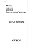
5 Installation and Wiring
5-1
Fail-safe Circuits
This section describes the fail-safe circuits that must be set up outside the CP1E.
Always set up safety circuits outside of the PLC to prevent dangerous conditions in the event of errors in
the CP1E CPU Unit or external power supply.
In particular, be careful of the following points.
Timing of Supplying Power to the PLC and the Controlled System
If the PLC’s power supply is turned ON after the controlled system’s power supply, outputs in Units such
as DC Output Units may momentarily not function properly.
To prevent any malfunction, add an external circuit that prevents the power supply to the controlled system from going ON before the power supply to the PLC itself.
Safety Circuit for Errors (Outputs Turned OFF)
When any of the following errors occur, PLC operation (program execution) will stop and all outputs
from the Units will be turned OFF.
• A CPU error (watchdog timer error) or CPU on standby
• A fatal error (memory error, I/O bus error, too many I/O points error, program error, cycle time
exceeded error, or FALS error)
Be sure to add any circuits necessary outside of the PLC to ensure the safety of the system in the event
of an error that stops PLC operation.
Safety Circuit after a Malfunction (When an Output Remains ON)
It is possible for an output to remain ON due to a malfunction in the internal circuitry of the Output Unit,
such as a relay or transistor malfunction. Always add any circuits necessary outside of the PLC to
ensure the safety of the system in the event that an output fails to go OFF.
External Interlock Circuits
When the PLC controls operation such as the clockwise and counterclockwise operation of a motor and
if there is any possibility of an accident or mechanical damage due to faulty PLC operation, provide an
external interlock such as the one shown below to prevent both the forward and reverse outputs from
turning ON at the same time.
Example:
Interlock Circuits
100.00
MC2
Motor
MC1 clockwise
operation
MC1
Motor
MC2 counterclock
wise operation
CP1E
100.01
5-2
A circuit like the one shown in the diagram on the left is required to prevent
outputs MC1 and MC2 from both being
ON at the same time even if both PLC
outputs CIO 100.00 and CIO 100.01
are both ON.
D3E Electronique Parc du Grand TROYES 3 Rond Point Winston CHURCHILL 10302 SAINTE SAVINE
Tél: 03 25 71 31 65 Fax: 03 25 74 38 82 Email: [email protected] www.d3e.fr