1
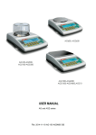
Adam Equipment PGL SERIES (P.N. 9326, Revision C2, December 2008) 1|Page © Adam Equipment Company 2008 Easy Reference: Model name of the scale: Serial number of the unit: Software revision number (Displayed when power is first turned on): Date of Purchase: Name of the supplier and place: 2|Page © Adam Equipment Company 2008 CONTENTS 2.0 3.0 INTRODUCTION...................................................................................5 SET UP .................................................................................................6 3.1 3.2 3.3 3.4 4.0 5.0 UNPACKING AND SETTING UP YOUR SCALE ................................................ 6 ASSEMBLING THE BALANCE (PGL 203 to PGL 8001)..................................... 6 LEVELLING THE BALANCE ............................................................................... 7 WARM-UP TIME ................................................................................................. 7 DISPLAY...............................................................................................9 KEYPAD .............................................................................................10 5.1 6.0 NUMERIC ENTRY METHOD ............................................................................ 11 BASIC OPERATION ...........................................................................12 6.1 6.2 6.3 6.4 7.0 INITIALISATION ................................................................................................ 12 PASSCODES .................................................................................................... 13 WEIGHING........................................................................................................ 13 WEIGHING UNITS ............................................................................................ 14 FUNCTIONS .......................................................................................15 7.1 7.2 7.3 7.4 8.0 PARTS COUNTING .......................................................................................... 15 PERCENT WEIGHING...................................................................................... 16 CHECK WEIGHING .......................................................................................... 17 DENSITY DETERMINATION ........................................................................... 19 CALIBRATION....................................................................................22 8.1 8.2 8.3 8.4 9.0 MANUAL CALIBRATION................................................................................... 22 AUTOMATIC CALIBRATION ............................................................................ 23 CALIBRATION ERRORS .................................................................................. 23 CALIBRATION REPORT................................................................................... 24 RS-232 INTERFACE...........................................................................25 9.1 9.2 9.3 HARDWARE ..................................................................................................... 25 STANDARD FORMAT....................................................................................... 27 INPUT COMMANDS USING REMOTE KEYS .................................................. 27 10.0 BATTERY OPERATION .....................................................................29 11.0 ERROR CHECKING ...........................................................................29 12.0 SUPERVISOR MENUS......................................................................30 12.1 12.2 12.3 12.4 12.5 12.6 ENABLE WEIGHING UNITS ............................................................................. 30 ENABLE WEIGHING MODES........................................................................... 31 ENABLE SERIAL INTERFACE PARAMETERS................................................ 31 SETUP PARAMETERS..................................................................................... 33 CALIBRATION SETUP...................................................................................... 34 PASSCODES .................................................................................................... 35 13.0 SPECIFICATIONS .............................................................................36 14.0 WARRANTY STATEMENT ................................................................38 3|Page © Adam Equipment Company 2008 4|Page © Adam Equipment Company 2008 2.0 INTRODUCTION Thank you for selecting the PGL Balance. This Instruction Manual will familiarize you with the installation, accessories, trouble-shooting, after sales service information, general maintenance of the balance, etc. and will guide you through the various applications. Please read this Manual thoroughly before starting the operation. If you need any clarifications, feel free to contact your supplier or Adam Equipment. PRODUCT OVERVIEW The PGL balances are ideal for laboratory and general purpose weighing. The balances can also be used for some advanced weighing functions. FEATURES: • Large easy to read LCD display with backlight • Standard applications include weighing, check weighing, percentage weighing, parts counting, and density determination • Bi-directional RS-232 interface • Can be configured to print a GLP Compliant report after each calibration to include the time, date, balance number and a verification of the calibration PGL series • • • • • • • • Multiple weighing units Capacity tracker Date and time Easy to use, sealed keypad Below balance weighing facility Password protection Security locking point (up to PGL 8001) Robust metal casing 5|Page © Adam Equipment Company 2008 3.0 SET UP 3.1 UNPACKING AND SETTING UP YOUR SCALE Remove the balance from the packing by carefully lifting it out of the box. Inside the box you will find everything needed to start using the balance- 3.2 AC adapter Four rubber pan supports Stainless Steel Top Pan Draught shield (for mg models only) This User Manual ASSEMBLING THE BALANCE (PGL 203 TO PGL 8001) Locate the balance on a solid surface, free from vibration Gently place the 4 pan supports (if not already fitted) and then the stainless steel pan on the weighing platform Place the draught shield frame and the top cover around the pan (PGL 203, 303 models only) Level the balance using the adjustable feet and spirit level Connect power to the balance For best performance, let the balance warm up for 30 minutes and calibrate before using 6|Page © Adam Equipment Company 2008 3.3 LEVELLING THE BALANCE After placing the balance in a suitable place, level it by using the spirit level on the rear of the balance. To level the balance turn the two adjustable feet at the rear of the balance until the bubble in the spirit level is centered. 3.4 WARM-UP TIME Attach the power supply cable to the connector on the rear of the balance. Plug the power supply module into the mains. The display will indicate the balance serial number (if set) and the software revision number followed by the capacity of the balance. Next the balance will run a self-test by displaying all segments followed by a symbol indicating the balance is in busy mode. If the balance serial number is not set the display will show dashes. The display will show zeroes accompanied by the 0 symbol. Before you start weighing, you have to wait for the balance to achieve a stable internal temperature. A stable sign ~ is shown when the balance is in stable condition. It will turn off if the balance is not stable. Exact zero is shown when the “0 “ symbol is on to the left of the display area. 7|Page © Adam Equipment Company 2008 3.5 LOCATING AND PROTECTING YOUR SCALE In order to keep your scale functioning at its best we suggest that you do the following: Avoid extremes of temperature. Do not place in direct sunlight or near air conditioning vents. Make sure the scale is located on a strong table and free from vibration. Avoid unstable power sources. Do not use near large users of electricity such as welding equipment or large motors. Do not mix batteries and use only the factory approved power adapter supplied with the machine. Do not use batteries and the AC adapter at the same time. Keep free from vibration. Do not place near heavy or vibrating machinery. Avoid high humidity that might cause condensation. Keep away from direct contact with water. Do not spray or immerse the scales in water. Do not place near open windows, air-conditioning vents or fans that may cause a draft and unstable readings. Keep the scales clean. Do not stack material on the scale / balance when it is not in use. 8|Page © Adam Equipment Company 2008 4.0 DISPLAY The LCD has unique symbols to indicate the following: 0 Zero Stable Net Net weight A bar graph indicating the proportion of the balance capacity being used by the weight on the pan g, kg, ct, oz, lb, ozt, GN, dwt, dr, tl H, tl Symbols shown for the units T, tl S, MM, T, ti, N, g/cc, Pcs, %, M, and Not all weighing units are used S Low Battery symbol. On when the battery voltage is low, signaling the battery should be recharged. INDICATORS “CAL” When calibration is occurring or is requested “ºC” When a temperature is shown “ti” For a time driven calibration “Net” When a net weight is shown “0%”, “100%” When the capacity tracker is showing percent of maximum range used 9|Page © Adam Equipment Company 2008 5.0 KEYPAD The keypad has the following keys to operate the balance. Keys [ 0/T ] or [Esc] [Unit] / or [Down] Primary function Secondary function To turn the balance to ON or Standby - A combined zero and tare function To escape from setup functions and modes -Selects weighing units by cycling through a set of enabled units To decrement or change a displayed value or scroll through options backwards -Scrolls through the options [Mode] / or [move right] Enters the Mode Selection Menu To advance a flashing digit by one position to the right. To go back by one step during setup functions [Print] / or [move left] Instructs the balance to print data To advance a flashing digit by one position to the left [Cal] / or [Up] Starts the calibration function To increase or change a displayed value or scroll through options forward [Setup]/ or [Enter] Enters the Setup parameters (Supervisor Menus) Enters a function or saves a value while manually entering unit weight or check weighing limits 10 | P a g e © Adam Equipment Company 2008 5.1 NUMERIC ENTRY METHOD To set a value when required, use the keys as given below- [Up] and [Down] keys to increase or decrease the flashing digit - [Advance] and [Back] keys to advance or move back the digit - [Enter] key to accept the value 11 | P a g e © Adam Equipment Company 2008 6.0 BASIC OPERATION 6.1 INITIALISATION 1) When the balance is first switched on, it will display the balance serial number (if set), software revision, model capacity and then all segments on the display will be shown. Overall the time taken is usually 5 -10 seconds. 2) If a passcode has been set, the display will show “PASSCODE” and the main display will show a zero. In this case you must enter the passcode to continue using the numeric entry method (see section 5.1). A different passcode may be set for a Supervisor to weigh or to have access to the selected User menus. If the passcode has not been set the balance will continue as below. 3) The display will show zero reading along with the zero symbol “→0←” and the weighing unit last used. If automatic time calibration is enabled the balance will calibrate after power up and again after the pre-set time interval. 12 | P a g e © Adam Equipment Company 2008 6.2 PASSCODES If a passcode has been set to limit access to the weighing functions of the balance the display will show “PASSCODES” with the main digit set to zero. The display will change to show 7 digits set to zero with the rightmost digit flashing. Use the numeric entry method (see section 5.1) to enter the code. Make sure to enter the correct passcode to continue. See the Section 12.6 for details. 6.3 WEIGHING 1) Press [→ →0/T← ←] to zero the balance, if required, “→0←” will be displayed 2) Place a mass on the pan and the weight will be displayed 3) If a container is used press [→ →0/T← ←] to tare the balance (zero the display) when the stable symbol “~” is on. “Net” will be displayed to indicate that the balance is tared 4) When the display shows zero, place the item to be weighed. Only the net weight will be displayed. The capacity tracker at the bottom of the LCD will indicate the weight graphically with respect to the maximum weighing capacity 5) At any time the [Unit] key can be pressed to select another unit. Use the [Up] or [Down] key to scroll through the units and select the desired unit by pressing the [Enter] key, the display will change to show the weight in the selected weighing unit. The available weighing units can be enabled or disabled by the user (see section 12.1). Only weighing units that have been enabled will be cycled through when the [Unit] key is pressed 13 | P a g e © Adam Equipment Company 2008 6.4 WEIGHING UNITS You can select alternative weighing units to display the weight by pressing the [Unit] key. The common weighing units are: Unit Symbol Conversion Factor 1g = Grams Kilograms Carat Ounces Pounds Troy ounces Grains Pennyweights Newtons Custom g kg ct oz lb ozt GN dwt N Custom 1 0.001 5 0.035273962 0.0022046 0.032150747 15.43236 0.643014865 0.00980665 As specified Conversion Factor 1 unit = grams 1.0 1000 0.2 28.349523 453.5924 31.103476 0.0647989 1.555174 101.921623 As specified If “CUSTOM” unit is selected, the balance will prompt for entering a multiplier by displaying “MULTIPLIER XX,XXX”, where “XX,XXX” is the last stored value. Any value ranging from 0.100 to 10.000 may be entered, by which the weight in grams will be multiplied before being displayed. If a multiplier of greater than 1.000 is entered, the number of decimal places displayed will be reduced by one. This multiplier value will be saved for the next use till it is changed by the user. It is possible to set the balance to display only grams. Grams will always be one of the units enabled, by default. The balance displays the alternate weighing units with as much precision as possible. For example, the 4000g x 0.1g balance could weigh up to: Grams Kilograms Carat Ounces Pounds Troy ounces Grains Pennyweights Newtons 14 | P a g e Unit g kg ct oz lb ozt GN dwt N Maximum 4000.0 4.0000 20000.0 141.100 8.8180 128.605 61730 2572.1 39.226 d= 0.1 0.0001 0.5 0.005 0.0005 0.005 2 0.1 0.001 © Adam Equipment Company 2008 7.0 FUNCTIONS When weighing, the user can access the applications that have been enabled (see section 12.2). • • • • • Weighing Parts counting Percent weighing Check weighing Density determination The selectable functions can be enabled using a similar method to the Units above by turning the functions on or off. 7.1 PARTS COUNTING This allows the user to weigh a sample of parts to compute an average unit weight and then determine the number of items being weighed by dividing the net weight by the unit weight value. The result is always a whole number of parts. The balance will have a preset number of parts to be used as a sample. These values are 10, 25, 50 or 100 items. Steps: 1) Press [Mode] and then the [Up] or [Down] key to select parts counting, “PARTS” will be displayed 2) Enter parts counting by pressing [Enter] 3) Press the [Up] or [Down] key to select the sample size, “REF QTY”, 10, 25, 50, 100, etc., then press [Enter] to confirm 4) When “LOAD XX Pcs” is shown place XX number of items on the pan and press [Enter] to compute the average piece weight. Display will indicate the busy symbol 5) Remove the sample when display shows “XX Pcs” and then place an unknown quantity on the pan. The balance will then compute the number of parts based upon the average piece weight. The display will show the result in Pcs 6) To count another item press [Mode] and continue from step 2. 7) To return to normal weighing, press [Mode] then press [Esc] 15 | P a g e © Adam Equipment Company 2008 8) During parts counting checks will be made to determine that the weight of the reference parts is large enough for reasonably accurate counting (weight of each piece should be > 1d) 7.2 PERCENT WEIGHING Percent weighing will be done by defining a certain weight to be 100%. The weight to be used can either be entered by the user or taken from a sample. Steps: 1) Press [Mode] and then the [Up] or [Down] key to select Percent weighing, “PERCENT” will be displayed 2) Press [Enter] to enter the function 3) Display will show, “PERCENT SAMPLE” 4) Press [Enter] to select the sample method (see step 5) or press the [Up] or [Down] key to select the manual entry of weight method (see step 9). 5) When “LOAD 100 %” is shown, add the sample 6) Press [Enter] to set this weight to be 100%, the busy symbol will turn on. When ready the display will show “100%” 7) Remove the sample and place an unknown sample to display the percentage weight 8) To set another weight as 100%, press [Mode] and continue from step 2 above. 9) To manually enter a value to be set as 100%, press [Up] or [Down] key when “PERCENT SAMPLE” is shown to select “PERCENT Ent Wt” 10) Press [Enter] to select the manually entered weight method 11) Enter the weight using the numeric entry method (see section 5.1) 16 | P a g e © Adam Equipment Company 2008 12) Place unknown sample to display the percentage weight 13) To perform percent weighing with another sample press [Mode] and continue from step 2 above. 14) To return to normal weighing, press [Mode] then press [Esc]. Note: Percentage will be displayed to the maximum number of decimal places based on the resolution of the balance. To increase or decrease by one decimal place, press the [Up] or [Down] key respectively. 7.3 CHECK WEIGHING During weighing of a sample the balance can be set to show if the weight is above or below an upper and a lower limit. The display will use the arrows under the fill guide to show the check weighing is operating. The arrows and bars between the arrows will indicate when the weight is below the lower limit, between the limits or above the upper limit. The buzzer can be set to be active when the weight is outside the limits (below the lower or above the upper) or within the limits (above the lower and below the upper limit), or turned off. If desired, only one limit needs to be set. If only one limit is set the other limit is considered to be zero (lower) or the maximum (upper). The Check weighing is not active from zero to 20 scale divisions however the arrows will still be turned on below the fill guide and the weight will still be displayed. Steps: 1) Press [Mode] and then the [Up] or [Down] key to select Check Weighing. When “CHECK” is displayed press the [Enter] key to enter Check Weighing mode 2) Press [Up] or [Down] to set the “LOW LIMIT” to “On” or “OFF” 3) Press [Enter] to proceed. If the “LOW LIMIT” was set to “On” the display will show the current low limit and allow you to change the limit using the numeric entry method (see section 5.1). The display will show the weigh in the current 17 | P a g e © Adam Equipment Company 2008 weighing unit. If the weighing unit is pounds: ounces the limit is set in decimal pounds, 1.500 lb = 1 lb 8oz. 4) Press [Enter] to proceed 5) If the “LOW LIMIT” was set to “OFF” or the setting of the low limit is complete, then the display will change to “HIGH LIMIT”. Use [Up] and [Down] to set the “HIGH LIMIT” to “On” or “OFF” 6) Press [Enter] to proceed 7) If the “HIGH LIMIT” was set to “On”, the display will show the current high limit which can be changed by using the numeric entry method (see section 5.1) 8) Press [Enter] to proceed 9) Next the beeper setting is displayed. Press [Up] or [Down] to scroll through the options – 10) “BUZZER OFF” (Beeper set to off at all times) 11) “BUZZER In” (Beeper will sound when the weight on the pan is within the limit) or 12) “BUZZER Out” (Beeper will sound when the weight on the pan is outside the set limits) 13) Confirm the beeper setting by pressing [Enter] 14) Press [Enter] again to start the Check Weighing 15) When a weight is placed on the pan now, the display will indicate whether the weight is below the LOW LIMIT between the LOW and HIGH LIMITS or higher than the HIGH LIMIT using the capacity tracker, 16) To perform check weighing with another sample press [Mode] and continue as before 17) To return to normal weighing, press [Mode] then press [Esc]. 18 | P a g e © Adam Equipment Company 2008 7.4 DENSITY DETERMINATION It is possible to determine the density of solids or liquids using this mode. The user selects the type of density to be determined and then enters values to be used by the balance. The density mode allows the user to use a special Density Kit or use the below pan weighing facility to perform the necessary weighing. DENSITY OF SOLIDS To perform the density of solids test, the user must have a method to immerse the sample in the chosen liquid. The density of the liquid must be known or determined from a look-up table. For water and ethanol the density will be calculated based on the temperatures entered using the numeric entry method (see section 5.1) Steps: 1) Press [Mode] and then [Up] and [Down] keys to select density 2) Press [Enter] to enter Density mode. 3) Press the [Up] and [Down] keys to select the solids or Liquid method when “DENSITY SOLId” or “DENSITY LIqUId” is displayed 4) Press [Enter] to select the solids method 5) Press [Up] or [Down] to select the liquid of choice- Water, Ethanol or Other 6) Press [Enter] to select the choice. For water and Ethanol the temperature will be asked for. Enter the temperature using the numeric entry method (see section 5.1) 7) For the “Other” choice the density will be asked for. Enter the density (g/cc) using the numeric entry method (see section 5.1) 8) Press [Enter] to continue 19 | P a g e © Adam Equipment Company 2008 9) The balance will request the weight of the sample in air by displaying “AIR WEIGHT”. Place the item on the pan or receptacle, if the density kit is used. Press [Enter] to determine the value 10) After completion of the air weighing, the balance will request the weight in liquid by displaying “LIQUID WT”. Submerge the item in the liquid and press [Enter] to start the liquid weighing. The balance will compute the density of the sample and display it as “DENSITY XXXX g/cc” 11) After completion of the liquid weighing, remove the item from the pan 12) Press [Mode] to continue with a new sample or press [Esc] to return to normal weighing DENSITY OF LIQUID When finding the density of a liquid, it is necessary to weigh a sample of known volume in air and then in the liquid. The volume of the sample must be entered by the user. The last known volume is stored for use at any time. If using the density determination kit, the volume of the plumb is marked on its support, i.e. 10.123 Steps: 1) Press [Mode] and then [Up] and [Down] to select Density mode. 2) Press [Enter] to select the Density mode 3) Use [Up] and [Down] to scroll through the solid or liquid method 4) When “DENSITY LIqUId” is displayed, press [Enter] to enter the liquids method 5) The volume will be asked for. Enter the volume using the numeric entry method (see section 5.1) or continue using the last volume entered 6) Press [Enter] to continue 20 | P a g e © Adam Equipment Company 2008 7) The balance will request the weight in air by displaying “AIR WEIGHT”. Place the glass plumb supplied with the density determination kit in air on the weighing pan and press [Enter] to start the air weighing 8) On completion of the air weighing, the balance will request the weight in liquid by displaying “LIQUID WT”. Submerge the glass disk in the liquid and press the [Enter] key. The balance will compute the density of the liquid and display it. Remove the item from the pan 9) Press [Mode] to continue with a new sample or press [Mode] then [Esc] to return to normal weighing 21 | P a g e © Adam Equipment Company 2008 8.0 CALIBRATION The PGL series can only be calibrated with an external mass. 8.1 MANUAL CALIBRATION Pressing the [Cal] key will start calibration. Calibration can also be called for after a set time period as determined by the user (see section 12.5). Calibration using External Calibration mass: 1) Pressing [Esc] will abort the calibration at any time 2) Check the display is at zero. Tare if necessary 3) Press the [Cal] key 4) The display will show the balance setting a new Zero condition by showing “LOAD 0”. Make sure the pan is empty then press the [Enter] key to continue 5) The balance will then show the value of the calibration mass required sounding a beep, for example “LOAD 1000 g” 6) If a different mass is desired press the up or down arrow key to show the alternate masses possible for the scale. PGL 203 PGL 303 PGL 2002 PGL 3002 PGL 4001 PGL 6001 PGL 8001 PGL 10001 PGL 20001 Mass1 100 g 100 g 1000 g 1000 g 2000 g 3000 g 4000 g 5 kg 10 kg Mass2 200 g 200 g 2000 g 2000 g 3000 g 4000 g 5000 g 10 kg 15 kg 3000 g 4000 g 5000 g 6000 g 6000 g 7000 g Mass3 Mass4 Mass5 22 | P a g e 300 g 8000 g © Adam Equipment Company 2008 20 kg 7) Place the mass on the balance. Press [Enter] to continue 8) The display will show the busy symbol and after calibration is complete it will display the weight. Remove the weight. 8.2 AUTOMATIC CALIBRATION The balance will ask for calibration when the balance has automatic calibration enabled and the conditions of the automatic calibration have been met. The calibration will be called for if the time since last calibration exceeds a preset time, typically 4 hours. The balance will call for calibration to be carried out by flashing the “CAL” symbol on the display. As soon as the balance is calibrated the symbol will be turned off. The Auto calibration feature can be enabled, disabled or changed by the user options to meet the requirements of the users. See section 12.5. 8.3 CALIBRATION ERRORS Occasionally during calibration an error will be detected. These errors can be caused by: Unstable readings Improper calibration weights being used Large shifts of zero from the factory settings When an error is found a displayed message will be shown and the calibration must be done again. If the balance has error messages more than once it is possible the mechanics have been damaged. 23 | P a g e © Adam Equipment Company 2008 8.4 CALIBRATION REPORT The calibration report will show the details from the balance and give the user a place to sign showing he did the calibration. <SOH> CALIBRATION REPORT Ser No: AE435402 ID No: 123321 Date: 05/03/2008 Time: 18:41:57 Cal: External Mass: 2000g The data for the form will be preceded by a start-ofheader <SOH> character (01H) and terminated with an end-of-transmission <EOT> character (04H). These characters will be ignored by a serial printer but will allow a computer program which reads the data to distinguish between this block report format and plain text. Carriage returns and line feeds complete each line. Calibration complete Signed: __________ <EOT> 24 | P a g e © Adam Equipment Company 2008 9.0 RS-232 INTERFACE The balances have the ability to send or receive data over the serial interface. The weighing data can be sent over the interface either automatically or when the user presses the [Print] key. The user has control over what data is to be printed. The following gives a description of the RS-232 interface. 9.1 HARDWARE The RS-232 interface is a simple 3 wire connection. The input and output connections are: Connector: 9 pin D-sub miniature socket Pin 2 input to balance RXD Pin 3 output from balance TXD Pin 5 Signal ground GND Handshaking is not applied. Baud rate: 4800, 9600, 19200, 38400 Parity: NONE (=8N1), EVEN (=8E1) or ODD (=8 O 1) All lines are terminated with carriage return and line feed (<CR><LF>). In continuous output mode, or if single-line output on demand is selected, the serial output format will be a single line in the form “1234.567 g<CR><LF>”. The format of the single-line output will change depending on the mode in which the balance is operating, as described below. 25 | P a g e © Adam Equipment Company 2008 If output on demand is selected, the user may optionally configure the serial output as a choice of 3 styles of form, either in a default format or in one of two custom formats. Each of the custom formats can be configured to output up to 15 lines of data. The data types that can be printed are: NAME TEXT PRINTED ID number Serial number Date Time Net weight Gross weight Tare weight Unit weight Count Reference weight Percent Checkweigh lower limit Checkweigh upper limit A blank line printed ID no.: xxxxxxxxxxxx Serial no. xxxxxxxxxxxx DATE dd/mm/yyyy TIME hh:mm:ss Net: xxx.xxx g Gross: xxx.xxx g Tare: xxx.xxx g Unit wt: xxx.xxx g Count: xxxx pcs Ref. wt: xxx.xxx g Percent: xx.xxx % Low: xxx.xxx g High: xxx.xxx g <CR><LF> only. Any of these can be printed on any of the 15 lines available. Not all items need to be used and any one can be used more than once. The data for each form will be preceded by a start-of-header <SOH> character (01) and terminated with an end-of-transmission <EOT> character (04). These characters will be ignored by a serial printer but will allow a computer program which reads the data to distinguish between this block report format and the single-line output format described above. 26 | P a g e © Adam Equipment Company 2008 9.2 STANDARD FORMAT The balance will print the following data as the standard form. The standard form cannot be changed. The format of the custom forms #1 and #2 will be the same as the standard form until modified by the user. Line 1 Line 2 Line 3 Line 4 Line 5 Line 6 Line 7 Line 8 Date Time Blank line ID number Blank line Result Blank line Blank line This will result in a printout that looks like: Date: 23/09/04 Time: 15:45 ID No: 123456 NOTE: The format of the results line will change depending on the mode in which the balance is operating, e.g. Normal weighing, Check weighing: “123.456 g” Parts counting: “1234 pcs” Percent weighing: “12.345 %” 9.3 INPUT COMMANDS USING REMOTE KEYS The balance can be controlled with the following commands sent using remote keys such as from a PC. The commands must be sent in upper case letters, i.e. “KT” not “kt”. Press the Enter key of the PC after each command (the action of Carriage Return is denoted as <CR> as shown below). 27 | P a g e © Adam Equipment Company 2008 Basic Input Commands: !KT<CR> Tares the balance to display the net weight. This is the same as pressing the [Zero / Tare] key when the balance is in the normal weighing mode. !KS<CR> Enters the Setup section. This is the same as pressing the [Setup] key when the balance is in the normal weighing mode. Once entered the Setup section, the balance can be controlled remotely using the Input Commands (as mentioned in this table) which will perform the same key functions as described in section 10.0 !KP<CR> Transmits data over RS-232 interface. This is the same as pressing the [Print] key when the balance is in the normal weighing mode. !KM<CR> Enters the Modes section. This is the same as pressing the [Mode] key when the balance is in the normal weighing mode. !KC<CR> Enters the Calibration section. This is the same as pressing the [Cal] key when the balance is in the normal weighing mode. !KU<CR> Enters the Unit selection section. This is the same as pressing the [Unit] key when the balance is in the normal weighing mode. Invalid Input Command: If an invalid command is received, then the command is returned as followsInvalid Command Message returned Remarks !NT<CR> !EU<CR> Command character is not ‘K’ !KK<CR> !EK<CR> Key character is not ‘T’, ‘S’, ‘P’, ‘M’, ‘C’ or ‘U’ !KT-<CR> !EF<CR> Command format error, <CR> is not the fourth character KT<CR> or No reply Either ‘!’ or <CR> is missing in the command string !KT - 28 | P a g e © Adam Equipment Company 2008 10.0 BATTERY OPERATION The scale may operate from a built in lead acid battery. During operation with the battery the backlight should be disabled for best battery life. Typical battery life 20 hours. If possible disable the backlight automatically if the external power supply is not turned on. The low battery symbol, power shutdown when battery voltage falls below certain levels and control of the battery charging all need to be included. There will not be any diode to show the state of charge as on other scales. 11.0 ERROR CHECKING During weighing the balance is constantly checking to see if the balance is operating within the limited parameters. The errors likely to occur are: A/D counts below lowest allowed value A/D counts above highest allowed value A/D not operating Maximum capacity exceeded Other errors may be detected during special functions or operations. These will be described in the section that applies. Error messages and the reasons are: Concerning A/D counts ERROR ADc UL ERROR ADc OL Concerning calibration ERROR StAb ERROR LOW or ERROR HIGH Concerning weighing ERROR LOW ERROR HIGH 29 | P a g e A/D counts below a limit A/D counts above a preset limit Calibration could not be completed because the results were not stable Calibration constant not within 20% of old calibration constant Weight display is below zero by >4%max Weight is above maximum plus 90d © Adam Equipment Company 2008 12.0 SUPERVISOR MENUS Pressing the [Setup] key while in normal weighing gives access to the menus. 1) When [Setup] is pressed and passcodes are not enable the display will show the message “SUPERVISOR”. If passcodes are enabled, the balance will ask for it by displaying “PASSCODE 0” 2) If a wrong code is entered an “ERROR CODE” message will flash and the balance will return to weighing mode 3) If the passcode has been enabled and entered, the balance will allow the operator to access the Supervisor’s menus 4) When the display shows “SUPERVISOR” press [Enter] to view the topics that can be modified 5) From this menu the user can enable/disable weighing units or modes, set balance parameters for the conditions, set time and date, set parameters for the RS-232 interface, calibration parameters and security parameters 6) The [Up] and [Down] keys will cycle through the main headings, pressing the [Enter] key will enter the heading and sub-parameters or options can be set. Press [Mode] to come out of a sub-menu or to [Esc] to return to normal weighing from any menu 12.1 ENABLE WEIGHING UNITS 1) When “UNITS” is displayed, press [Enter]. The display will show the symbol for the first unit, e.g. kilogram, kg, together with its enable state “OFF” or “On”. The user can then enable or disable the carats unit by using [Up] or [Down]. Pressing [Enter] will confirm the setting and will advance to the next weighing unit. Repeat for each weighing unit in turn. Gram is always set to “On” 2) Press [Mode] to advance to setting of the next menu or press [Esc] to return to normal weighing 30 | P a g e © Adam Equipment Company 2008 12.2 ENABLE WEIGHING MODES Same steps are followed to enable or disable the weighing modes. 1) Press [Enter] when “MODES” is displayed. The display will show the first mode i.e., Parts Counting (“PARTS”) together with its enabled state “OFF” or “On”. The user can enable or disable the parts counting mode by using [Up] or [Down]. Pressing [Enter] will confirm the setting and will advance to the next weighing mode. Repeat for each mode in turn 2) Press [Mode] to advance to setting of the next menu or press [Esc] to return to normal weighing 12.3 ENABLE SERIAL INTERFACE PARAMETERS The parameters affecting the serial setup are set in a similar manner to the other parameters. Press [Enter] when “SERIAL” is displayed to enter the sub-menu. The parameters that can be set are: ENABLE The serial port can be set to On or OFF BAUD RATE Set the Baud Rate to 4800, 9600, 19200 or 38400 PARITY Set the Parity to NONE, EVEN or ODD 8 data bits and one stop bit are always used, (8n1, 8E1, 8o1). STABLE To print when stable (On) or regardless of stability (OFF) CONTINUOUS Set the RS-232 to send data continuously to On or OFF PERIODIC Set the RS-232 to send data periodically (set in seconds) to On or OFF. If On is selected, the value can be changed between 1 and 999 seconds, using [Up] and [Down] FORMAT To send data as a single line of data, using the standard format or using a customer designed format (FORM 1 or FORM 2). During continuous or periodic printing only the weight is printed. Forms are not available. 31 | P a g e © Adam Equipment Company 2008 Format of custom forms #1 and #2 If FORM1 or FORM2 is selected, it can be changed by the user using a selection of available data. By default the 2 forms are the same as the standard form unless changed by the user as below. When FORM 1 or FORM 2 is selected the user can set the information to be printed on each line of the form. Pressing the [Up] or [Down] keys will cycle through the options available. The options are: INST ID Instrument ID number SER No Serial Number TIME Time DATE Date NET Net Weight (Gross weight – Tare Weight) GROSS Gross Weight TARE Tare Weight UNIT Unit weight in parts counting mode COUNT Number of items in parts counting mode REF 100% weight in percent weighing mode PERCENT Percentage of reference weight in percent weighing LO LIMIT Low Limit when check weighing HI LIM High Limit when check weighing Cr Lf Inserts a blank line END Signifies the end of the report When END is entered the display returns to the RS-232 Sub-menu Enter the data to be printed on the first line by pressing the [Up] or [Down] key to cycle through the options. If the current information is OK then press the [Setup/Enter] key to move to the next line. e.g. “LINE No1” “DATE” - prints date Select a code for one of the preset data formats as detailed above. 32 | P a g e © Adam Equipment Company 2008 The next line shows: “LINE NO 2” “TIME” - prints time Only one item can be entered per line. Continue until the formatting of the form is complete. There are 15 lines of possible data. After the 15th line has been set or “END” has been selected, the balance will return to the RS-232 Sub-menu. Press [Mode] to advance to setting of the next menu or press [Esc] to return to normal weighing. 12.4 SETUP PARAMETERS The user parameters that control the balance are shown under the SETUP. When “SETUP” is displayed, press the [Setup/Enter] key. The options for each parameter can be scrolled through by using the [Up] or [Down] key. TIME DATE Set Time using the numeric entry method (see section 5.1) DATE FORM EUROPE (dd/mm/yy) USA (mm/dd/yy) ASIA (yy/mm/dd) Set Date using the numeric entry method (see section 5.1) USER ID Enter a user number to identify the user or the balance BUZZER On= Enable BACKLIGHT On OFF POWER DOWN Set the time after which the unit will go into Stand-by power settings, On=Enable, OFF=Disable, If set to On-the options are 1 to 9 minutes FILTER Set a value for the amount of filtering to be done, set to normal, slow or fast. STABILITY Set a value to be used to determine balance stability, set a value of 1, 2, 5 or 10d. A larger number corresponds to a larger stable zone. AUTO ZERO Can be set to On or OFF to enable the auto-zero function. If set to On- select from 1, 2 or 5d OFF= Disable AUTO The sub-menu is entered by pressing [Enter] – 33 | P a g e © Adam Equipment Company 2008 1) Use the [Up] and [Down] keys to increase or decrease the value for setting. Press [Enter] to accept the setting and advance to the next item in the menu 2) Press [Mode] to advance to setting of the next parameter or [Esc] to return to normal weighing 12.5 CALIBRATION SETUP This menu allows the user to set the calibration parameters. Press [Enter] when “CAL SETUP” is displayed to select the calibration parameters The options for each parameter can be scrolled through by using the [Up] or [Down] key ENABLE CAL REPORT NO =operator calibration is disabled YES=operator calibration is enabled On = Enabled. Prints out Calibration report after successful calibration OFF = Disabled TIME CAL On = Enabled. Select time from 1 to 24 hours. OFF = Disabled Press [Mode] to advance to setting of the next menu which is “PASSCODES” or [Esc] to return to normal weighing. 34 | P a g e © Adam Equipment Company 2008 12.6 PASSCODES To enable the security features in this balance it is necessary to set passcodes. There are 2 passcodes called Operator Passcode and Supervisor Passcode. The Operator Passcode allows an authorised user to operate the basic weighing functions of the balance but will not allow access to the Supervisor Menus if the Supervisor Passcode has been set. To change or disable a Passcode it will be necessary to enter the current passcode. Press [Enter] when “PASSCODES” is displayed to enter this section. Select either Operator or Supervisor passcode using the [Up] or [Down] keys. Press [Enter] to select the passcode to change. Press [CAL] to enter the current passcode (OLD) first then enter a new passcode if desired. Use the numeric entry method (see section5.1). A passcode set to zero will disable the security feature and allow unlimited access. Forgotten Passcodes Keep a record of the passcode to ensure you can access this section again. If however you have forgotten your passcode you can still gain access by entering a universal code. If you have forgotten the current passcode a code of “15” will always allow you to enter the Supervisor area. Using the Supervisor menus go to the PASSCODE section and reset the operator or Supervisor passcode using the “15” code as the old number when asked. 35 | P a g e © Adam Equipment Company 2008 13.0 SPECIFICATIONS Maximum Capacity Readability Repeatability (s.d.) Linearity ± Pan Units of Measure Functions Overall (wxdxh) PGL 203 PGL 303 200 g 300 g 0.001 g 0.001 g 0.002 g 0.003 g 0.004 g 0.006 g 145 x 125 mm / 5.7 “ X 7.6” grams, milligram, carat, grains, Newtons, troy ounce, pennyweights, ounce, and custom Weight, percent weighing, parts counting, check weighing , density determination Dimensions 251 × 358 × 104 mm 9.9” x 14.1” x 4.1” Net Weight Maximum Capacity Readability Repeatability (s.d.) Linearity ± Pan Units of Measure Functions Overall Dimensions (w x d x h) Net Weight 36 | P a g e PGL 2002 PGL 3002 2000 g 3000 g 0.01 g 0.01 g 0.02 g 0.03 g 0.04 g 0.06 g 192×192mm / 7.6” x 7.6” grams, kilograms, carat, grains, Newtons, troy ounce, pennyweights, ounce, and custom 4 kg / 8.8 Lb. PGL 4001 4000 g 0.1 g 0.2 g 0.4 g PGL 6001 6000 g 0.1 g 0.2 g 0.4 g 192×192mm / 7.6” x 7.6” PGL 8001 8000 g 0.1 g 0.2 g 0.4 g grams, kilograms, carat, grains, Newtons, pounds, ounces, pound:ounce, and custom Weight, percent weighing, parts counting, check weighing , density determination 251 × 358 × 104 mm 9.9” x 14.1” x 4.1” 4 kg / 8.8 Lb. © Adam Equipment Company 2008 PGL 10001 10 kg 0.1 g 0.2 g 0.4 g Maximum Capacity Readability Repeatability (s.d.) Linearity ± Pan 400 x 300 mm 15.7” x 11.8” grams, kilograms, carat, grains, Newtons, pounds, ounces, pound:ounce, and custom Units of Measure Functions Overall (wxdxh) PGL 20001 20 kg 0.1 g 0.2 g 0.4 g Weight, percent weighing, parts counting, check weighing , density determination Dimensions 455 × 400 × 95 mm 17.9” x 15.7” x 3.7” Net Weight 6 kg / 13.2 Lb. Common Specifications: Date and Time Weigh below Interface Stabilization Time Operating Temperature Battery backed real time and date standard Standard access point RS-232, bi-directional 2 Seconds typical 0°C - 40°C 32ºF – 104ºF Battery Power supply (external) Calibration 37 | P a g e Lead Acid Rechargeable 12VDC / 500 mA (min) Automatic External © Adam Equipment Company 2008 14.0 WARRANTY STATEMENT Adam Equipment offers Limited Warranty (Parts and Labor) for the components failed due to defects in materials or workmanship. Warranty starts from the date of delivery. During the warranty period, should any repairs be necessary, the customer must inform the supplier or Adam Equipment. The company or its authorised Technician reserves the right to repair or replace any components at its own discretion. Any shipping costs involved in sending the faulty units to a service centre is the customers responsibility. The warranty will cease to operate if the equipment is not returned in the original packaging and with correct documentation for a claim to be processed. All claims are at the sole discretion of Adam Equipment. This warranty does not cover equipment where defects or poor performance is due to misuse, accidental damage, exposure to radioactive or corrosive materials, negligence, faulty installation, unauthorised modifications or attempted repair or failure to observe the requirements and recommendations as given in this User Manual. Repairs carried out under the warranty does not extend the warranty period. Components removed during the warranty repairs become the company property. The statutory right of the purchaser is not affected by this warranty. The terms of this warranty is governed by the UK law. For complete details on Warranty Information, see the terms and conditions of sale available on our web-site 38 | P a g e © Adam Equipment Company 2008 Manufacturer’s Declaration of Conformity This product has been manufactured in accordance with the harmonised European standards, following the provisions of the below stated directives: Electro Magnetic Compatibility Directive 2004/108/EC Low Voltage Directive 2006/95/EC Adam Equipment Co. Ltd. Bond Avenue, Denbigh East Milton Keynes, MK1 1SW United Kingdom FCC COMPLIANCE This equipment has been tested and found to comply with the limits for a Class A digital device, pursuant to Part 15 of the FCC Rules. These limits are designed to provide reasonable protection against harmful interference when the equipment is operated in a commercial environment. The equipment generates, uses, and can radiate radio frequency energy and, if not installed and used in accordance with the instruction manual, may cause harmful interference to radio communications. Operation of this equipment in a residential area is likely to cause harmful interference in which case the user will be required to correct the interference at his own expense. Shielded interconnect cables must be employed with this equipment to insure compliance with the pertinent RF emission limits governing this device. Changes or modifications not expressly approved by Adam Equipment could void the user's authority to operate the equipment. W EEE COMPLIANCE Any Electrical or Electronic Equipment (EEE) component or assembly of parts intended to be incorporated into EEE devices as defined by European Directive 2002/95/EEC must be recycled or disposed using techniques that do not introduce hazardous substances harmful to our health or the environment as listed in Directive 2002/95/EC or amending legislation. Battery disposal in Landfill Sites is more regulated since July 2002 by regulation 9 of the Landfill (England and Wales) Regulations 2002 and Hazardous Waste Regulations 2005. Battery recycling has become topical and the Waste Electrical and Electronic Equipment (WEEE) Regulations are set to impose targets for recycling. 39 | P a g e © Adam Equipment Company 2008 ADAM EQUIPMENT is an ISO 9001:2000 certified global company with more than 35 years experience in the production and sale of electronic weighing equipment. Adam products are predominantly designed for the Laboratory, Educational, Medical, retail and Industrial Segments. The product range can be described as follows: -Analytical and Precision Balances -Compact and Portable Balances -High Capacity Balances -Moisture analysers / balances -Mechanical Scales -Counting Scales -Digital Weighing/Check-weighing Scales -High performance Platform Scales -Crane scales -Medical Scales -Retail Scales for Price computing For a complete listing of all Adam products visit our website at www.adamequipment.com © Copyright by Adam Equipment Co. Ltd. All rights reserved. No part of this publication may be reprinted or translated in any form or by any means without the prior permission of Adam Equipment. Adam Equipment reserves the right to make changes to the technology, features, specifications and design of the equipment without notice. All information contained within this publication is to the best of our knowledge timely, complete and accurate when issued. However, we are not responsible for misinterpretations which may result from the reading of this material. The latest version of this publication can be found on our Website. www.adamequipment.com 40 | P a g e © Adam Equipment Company 2008