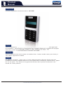
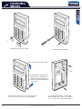
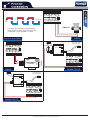
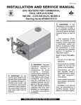
1
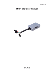
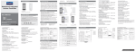
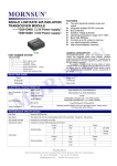
CCTV & Security Distributor
Integrated Access Controller
Installation Manual
Quality Assurance
Technical Innovation
45
0
Sincere and Faithful
Human-centered Design
3000
LED
1
4
7
ProVisual, Inc.
2
5
3
6
8
9
0
#
Product Manual
Installation Manual
Product Connection
Function Debugging
Product Maintenance
Home & Business Security Solutions
Product
Manual
CCTV & Security Distributor
Product Series
Provisual Integrated Access Control Series: AC-930P
Features
Anson Integrated Access Control is characterized by its elegant design and convenient application
and installation, which is especially suitable for office buildings and shops. The device is equipped
with built-in reader and can work both as controller and reader.
Operation
Instruction
Anson Integrated Access control should be installed indoor. Please consider water-proof facility in
case outdoor application is needed.
Notice
For detailed information, please refer to Product Manual and Wiring Diagram. Please make sure
installation is correctly completed before turn on the power. When connect any external device, please
turn off the power. This manual is only a general instruction and all products mentioned in this
manual are Anson products.
Home & Business Security Solution
Product
Maintenance
CCTV & Security Distributor
Common Question
1. If there is no sound when card is presented to the reading area, the reading function maybe
damaged.
2. If there is no sound when press the keys, the keypad maybe damaged.
3. When add card, if the device exits program mode automatically, the memory maybe
damaged.
4. If valid card is read and OK light is on, while relay does not act, the lock control may
malfunction.
5. If relay keeps on in open state, buzzer keeps buzzing, and SW-GND is short or lower than
3.5V , the keys maybe damaged.
6. MenCi-GND is short or lower than 3.5V, the door magnet input maybe damaged.
7. Voltage of DATA0, DATA1 and GND should be higher than 3.5V, otherwise exterior reader can
not work properly.
8. When RS485 is applied, voltage between 485+ and 485- is around 5 voltages.
The life of products is related to application environment and application method. Please carefully
follow the product manual and installation manual.
In case of any problem, please contact with our technical support instead of self- repairment.
Please keep the original state of the products when sending back for repair. Please notify us
if you have any special demand, and we will feedback within 48 hours.
ProVisual, Inc.
Technical Support Department
[email protected]
Toll Free: 1(800)593-6955
Home & Business Security Solution
Product
Manual
CCTV & Security Distributor
30mm
Fixing Hole
88m m
Fixing Hole
Jumper
1
2
3
4
5
6
7
8
9
0
#
RX
GND
12V 485 232 TX
GND
DAT0
485+
DAT1
485SW
GND
2C
2NO
MenC1
GND
1NO
1C
BELL
1NC
BELL
Fixing Hole
The Front
The Back
The Side
设备参数
Product Parameters
Working Voltage:DC9-15V
Static Current:≤120mA
Reading Distance: 5-10cm
Card Type: ID card
Working Temperature: -15℃~55℃
Card Capacity: 3000pcs
Input Interface: 1pcs exit button, 1pcs door magnet
Output Interface: 1pcs lock control port (normal open, normal close), 1pcs
door magnet alarm output port (normal close)
Communication Mode: RS232/RS485
Reader Interface: Wiegand 26
Home & Business Security Solution
AC-930P
150mm
Installation
Manual
CCTV & Security Distributor
AC-930P
1. Remove the two keys first.
2. Unfasten the two screws.
Push up the back cover to open
First open the lower part of
backcover for around 1cm.
Please note that open too
wide may lead to damage to
the device.
3. Open the back cover and connect the
device according to the wiring diagram.
4. Fix the backcover on the wall
Reassemble the device. (according
to 1, 2 and 3 in reversed order.
Home & Business Security Solution
Product
Connection
CCTV & Security Distributor
RX
GND
Power
Interface
485 232
12V
485+
DAT1
Exit Button
Interface
Door Magnet
Interface
Door bell
Interface
RS485
Interface
485-
SW
GND
RX
GND
12V 485 232 TX
GND
DAT0
485+
DAT1
485SW
GND
2C
2NO
MenC1
GND
1NO
1C
BELL
1NC
BELL
RS232
Interface
TX
GND
DAT0
Reader
Interface
AC-930P
AC-930P Interface
2C
MenC1
2NO
GND
1NO
BELL
1C
Door Magnet
Alarm Output
Interface
Lock Control
Interface
1NC
BELL
Power Interface
GND
+12V
RX
TX
GND
485+
4852C
2NO
1NO
1C
1NC
GND
+12V
AC-9 30P Interface
RX
TX
GND
485+
4852C
2NO
1NO
1C
1NC
GND
12V
DAT0
DAT1
SW
GND
MenC1
GND
BELL
BELL
GND
12V
DAT0
DAT1
SW
GND
MenC1
GND
BELL
BELL
AC-930 P Interface
Power Interface
* Valid state:door magnet is normal open.
V+
VNO
COM
NC
Fail-safe
Connect with Power
Connect with EM Lock
-
AC-9 30P Interface
+12V
GND
+12V
GND
SIGNAL
SIGNAL
+12V
GND
Electric Bolt
Door Magnet
Connect with Electric Lock
Power Interface
Iron Core Cover Plate
Home & Business Security Solution
Power Interface
AC-9 30P Interface
RX
TX
GND
485+
4852C
2NO
1NO
1C
1NC
RX
TX
GND
485+
4852C
2NO
1NO
1C
1NC
Fail-secure
GND
12V
DAT0
DAT1
SW
GND
MenC1
GND
BELL
BELL
GND
12V
DAT0
DAT1
SW
GND
MenC1
GND
BELL
BELL
+
*Valid state:door
magnet is normal open.
Connect with Electric Bolt
Product
Connection
CCTV & Security Distributor
GND
12V
DAT0
DAT1
SW
GND
MenC1
GND
BELL
BELL
AC-930P Interface
Close
Open
Automatic Door Interface
( Switch Signal)
Barrier Interface
(Electric Level Signal)
Stop
RX
TX
GND
485+
4852C
2NO
1NO
1C
1NC
RX
TX
GND
485+
4852C
2NO
1NO
1C
1NC
For this type of connection, the
barrier switch is closed in normal
status. When user presents
card or presses the exit button,
the barrier will be opened, The
opening time depends on the
door-open delay time. It is
recommended to install ultra-red
and ground sensor for protection.
Common end
COM1
COM2
Connect with Barrier
The automatic door is open when
COM1-COM2 is short circuit.
Connect with Automatic Door
GND
12V
DAT0
DAT1
SW
GND
MenC1
GND
BELL
BELL
GND
12V
DAT0
DAT1
SW
GND
MenC1
GND
BELL
BELL
AC-930P Interface
RX
TX
GND
485+
4852C
2NO
1NO
1C
1NC
RX
TX
GND
485+
4852C
2NO
1NO
1C
1NC
AC-930P Interface
Exit Button
Active Boorbell
Connect with Door Bell
GND
12V
DAT0
DAT1
SW
GND
MenC1
GND
BELL
BELL
GND
12V
DAT0
DAT1
SW
GND
MenC1
GND
BELL
BELL
AC-930P Interface
+12V
GND
+
Connect with Alarm Device
AC-930P Interface
Black
Red
Green
White
1
2
3
4
5
6
7
8
9
*
0
#
262RP
Power Interface
接读卡器
Connect with Reader
Home & Business Security Solution
RX
TX
GND
485+
4852C
2NO
1NO
1C
1NC
-
RX
TX
GND
485+
4852C
2NO
1NO
1C
1NC
Alarm Light
AC-930P
GND
12V
DAT0
DAT1
SW
GND
MenC1
GND
BELL
BELL
AC-930P Interface
Product
Connection
CCTV & Security Distributor
485485+
Converter
Computer
Interface
DB9-Hole
For 485 communication, please follow
the diagram for connection and no other
connection mode should be used.
12345
RS232
Connect with RS485
Connect with
PC or Router
Rs232
RX
GND
12V 485 232 TX
GND
DAT0
485+
DAT1
485SW
GND
2C
2NO
MenC1
GND
1NO
1C
BELL
1NC
BELL
DB9-Hole
232
485
DC9~30V
12345
AC-930P Interface
Rs232
ASV-TCP/IP
9~30V+
9~30V485+
Rj45
Rs485
RS232
RS485-RS232
Convertor
Computer
Interface
AC-930P Interface
PWD
RxD
TxD
T/R+
T/RGND
RX
GND
12V 485 232 TX
GND
DAT0
485+
DAT1
485SW
GND
2C
2NO
MenC1
GND
1NO
1C
BELL
1NC
BELL
RS485
485-
RS485
RS232\TCP/IP
Connect with
PC or Router
Rs485
232
485
DC9~30V
Rs232
AC-200TCP
9~30V+
9~30V485+
Rj45
Rs485
485-
RX
GND
12V 485 232 TX
GND
DAT0
485+
DAT1
485SW
GND
2C
2NO
MenC1
GND
1NO
1C
BELL
1NC
BELL
AC-930P Interface
RS485\TCP/IP
Home & Business Security Solution
AC-930P
RX
GND
12V 485 232 TX
GND
DAT0
485+
DAT1
485SW
GND
2C
2NO
MenC1
GND
1NO
1C
BELL
1NC
BELL
AC-930P Interface
Function
Debugging
CCTV & Security Distributor
Invalid Card: If the reader sounds twice after the card is
presented to the reading area for one second, the card is invalid.
Valid Card: If after the card is presented to the reading area for
0.5 seconds, the reader sounds once, green lights on and
delay acts, then the card is valid.
Test the Keypad
When the buzzer sounds once,
Dial “*”, the orange light flashes; Input“000000”, the orange
light turns on and device enters program mode. This means
the keypad is OK.
1
2
3
4
5
6
7
8
9
0
#
Test Output
GND
12V
DAT0
DAT1
SW
GND
MenC1
GND
BELL
BELL
AC-930P Interface
Adjust the multimeter to
, When the power is on,
in normal state, 1C- 1 NC is short circuit , while 1 C- 1 NO
is open circuit. When present the valid card or press
the exit button, 1C-1NC turns into open circuit, while 1C1NO is short circuit.
RX
TX
GND
485+
4852C
2NO
1NO
1C
1NC
1NC
1C
1C
1NO
A
GND
12V
DAT0
DAT1
SW
GND
MenC1
GND
BELL
BELL
AC-930P Interface
1NC
Normal State
1NO
Door-open State
Test Input
RX
TX
GND
485+
4852C
2NO
1NO
1C
1NC
If valid default input is normal open, no input available for the
device when input signal is open-circuit; while input available
when input signal is close-circuit. The status reversed when
valid default input is normal close.The user can decide the
type of default input setup in the software. AC-930P has two
input interfaces: SW-GND is button input; MenCi-GND is door
magnet input. Both of them can be changed in “channel setup”.
Home & Business Security Solution
AC-930P
Test Reading Card
Test Reading Card
Function
Debugging
CCTV & Security Distributor
3. Get the card
number
After the exterior device is connected with AC-930P, please
select Tools---Card Register in the software program. Then,
select the exterior device and start to read the card. If you
can find the card number in the list, it means the exterior device
works correctly.
2.Start to read card
Setup the Jumper
Rs232
Rs485
Test the Communication
AC-930P has two kinds of communication modes: RS232
and RS485. User can chose the communication mode by
setting up the jumper. AC-930P can connect with PC serial port,
and one serial port only connects with one AC-930P.
RS485 signal should be converted to RS232 signal before it
can communicate with PC. RS485 can connect with
multiple devices. After ASI-8930 is connected with PC, user
can detect AC-930P address by detecting serial port (please
refer to the user manual to setup the address). If
“connected” is displayed, the communication is ok. User
can get version and model number of AC-930P by inputting the
address and clicking Auto Detect.
Test the LCD
Provisual
2007-04-16
14:20
1
2
3
4
5
6
7
8
9
0
#
The LCD will display the Provisual and the time, after turn
on the power for AC-930P.
Test the time of AC-930P
Time adjustment is shown in the picture on the left. The time of
controller should be in consistent with PC. User can get
updated time for controller by press“Refresh”. If controller
time is incorrect, card record may get lost, validity of cardread is in doubt, and moreover, valid card may turn into be
invalid.
PC time should be in consistent with controller time;
* otherwise the reader may not work properly.
Home & Business Security Solution
AC-930P
Connect with Exterior Identification Device
1. Select the device
Product
Maintenance
CCTV & Security Distributor
1. If there is no sound when card is presented to the reading area, the reading function maybe damaged.
2. If there is no sound when press the keys, the keypad maybe damaged.
3. When add card, if the device exits program mode automatically, the memory maybe damaged.
4. If valid card is read and OK light is on, while relay does not act, the lock control may malfunction.
5. If relay keeps on in open state, buzzer keeps buzzing, and SW-GND is short or lower than 3.5V , the
keys maybe damaged.
6. MenCi-GND is short or lower than 3.5V, the door magnet input maybe damaged.
7. Voltage of DATA0, DATA1 and GND should be higher than 3.5V, otherwise exterior reader can not work
properly.
8. When RS485 is applied, voltage between 485+ and 485- is around 5 voltages.
9. The LCD have no information to be displayed, after turn on the power for AC-930P. The starting
program maybe damaged.
The life of products is related to application environment and application method. Please carefully follow
the product manual and installation manual.
In case of any problem, please contact with our technical support instead of self-repairment.
Please keep the original state of the products when sending back for repair. Please notify us if you
have any special demand, and we will feedback within 48 hours.
Urgent Maintenance:
1. When the exterior reader can not read the cards, please
test the voltage of DATA0—GND and DATA1---GND. If the
voltage is less than 3.5V, please weld TVS2, TVS3.
2. When door magnet input fails, please test the voltage
between Menci and GND. If the voltage is less than 3.5V,
please weld TVS5.
3. When exit button input fails, please test the voltage between
SW and GND. If the voltage is less than 3.5V, please weld
TVS4.
PCB
Home & Business Security Solution
AC-930P
Common Question