Transcript
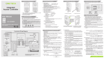
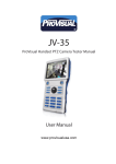
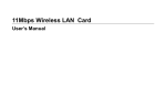
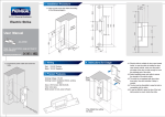
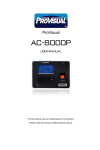
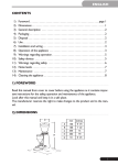
5. Communication Mode Setup
4. Installation Instruction
3. Product Parameters
0
#
exterior card interface, 2 groups of output interfaces, DC12/3A
3.4 Network Interface: RS232/RS485 interface
Entrance/Exit Mode:
2. Important Notices
6
8
9
0
#
AC-930P
Read the manual before usage and keep for
future reference.
JP1
http://www.provisualusa.com
JP1
JP1
Sound Indication:
Device sounds once is keypad input; device sounds twice continuously
means error or exit.
Basic Setup
1. System Initate
2. Address Setup ▼
Password
Manage
Change Cardholder Password
Change Administrator Password
Delete card
Add Card
Once device enters edit menu, the user can setup the controller. Push # to return to
upper level menu. For setup hierarchy, please note the following:
Select 2
Old Address: 00
New Address:
Input 2-digit
address
1. System Initate
2. Address Setup ▼
Initiation address is 00; input the new address and return. The device sounds
twice and returns in case of wrong input.
7.2.3 Time Adjustment
Time adjustment is to synchronize time of controller with real time. The time can
also be setup off-line. (Only 2-digit of year can be inputted),week format (01-07);
1. System Initate
2. Address Setup ▼
Push 9 for
page down
3. Adjust Time
4. Anti-disassemble
1. System Initate
2. Address Setup ▼
Delete All Card
Add-Single-Card
Delete Card
Add-Multi-Card
Open Password
Screen Password
Card and Password
Only Card
"
"shows there are other pages to be shown, you can use key 6 and key
9 for moving the page. 6 for page up and 9 for page down.
4.3 Open the back cover and connect the
device according to the wiring diagram.
——Voltage clamp protection
——All outputs adopt spark depress circuit and absorption circuit
Select 3
--YY--MM-DD
--HH--MM
1. Basic Setup
2. Pass Mode
1. System Initate
2. Address Setup ▼
page down
3. Adjust Time
4. Anti-disassemble
Select 4
ON:00
OFF:01
Download the message to device after inputting the message in software.
This function is applied to AC-930P only. There can be max. 9 Chinese
characters and 18 English letters for each row.
1. Only Card
2. Card &PSW ▼
Select 1
1. 0pen Delay
2. 0pen Mode
Open by Card and Password
Select 2
1. Only Card
2. Card &PSW ▼
Select 2
1. 0pen Delay
2. 0pen Mode
1. 0pen Delay
2. 0pen Mode
Door will be opened once the card is valid and card-holder password is
correctly inputted
1
2
3
4
5
6
7
8
9
0
#
enter 9 to
next page
3.Info. Distribute
select 3
Cancel(00)
Enter 00 to delete setup and return to the default setup. Information can also be deleted
from software.
T/RGND
读卡器
接口1
RS485-RS232
Convertor
Connected with
Fail-Secure
Alarm Light
AC-322MA
NC
COM
NO
VV+
Door
Magnet
Exit Button
262RP
T/R+
Detailed installation procedure, Refer to Installation & Commissioning
Manual. Strictly follow the diagram for connection.
Any modification will be notified.
Doorbell
Exterior Reader
1. Add card
2. Delete card
select1
1. Add_Multi_card
2. Add_Single_card
select 1
Input start number
read card
please read card
push#to exit
when finish
Add single card
User can define a certain number to a card,only one card can be defined in one
time.(If the number had been defined to other card before, the new defined card
will overwrite the original card)
1. Add card
2. Delete card
select1
1. Add_Multi_card
2. Add_Single_card
select 2
7.5 Password management
Password management refers to the management of administrator password and
card-holder password.Administrator password is used to enter Edit status. Cardholder password is used to open the door in the password or card+password dooropen mode,they are the same one.
7.5.1 Modify administrator password
Default administrator password is 000000, if two inputs are inconsistent, the device will
automatically return to the higher-lever menu.
3. Employee Manage
4. Password manage
select 4
1. Change Admi PWD
2. Change User PWD
select 1
Input new PSW:
input password
Input number
modified
1. Change Admi PWD
2. Change User PWD
input password
Input again:
input code
Screen Password
7.4
Select 2
3. Screen PSW ▲
4. Open PSW
Select 3
1. 0pen Delay
2. 0pen Mode
Input door-open password (card-holder password) can not open the door
1. Door-open Delay
2. Door-open Mode▼
GND
+12V
DATA0
DATA1
1. Add_Multi_card
2. Add_Single_card
result shown
Delete information release,setup as following:
Door will be opened once the card is valid
1. Door-open Delay
2. Door-open Mode▼
AC 90~220V
input number
Open by Card
1. 0pen Delay
2. 0pen Mode
RS232 Mode
15:00 meeting today
staff training tomorrow
Select 2
RX
GND
12V 485 232 TX
GND
DAT0
485+
DAT1
485SW
2C
GND
2NO
MenC1
1NO
GND
1C
BELL
1NC
BELL
AC90~220V
6.1 Selection of exterior components may be based on installation environment.
However, the selection should be in accordance to existing National and
International Standards as well as matched with the controller. A careful study
on the instructions on exterior components selection is strongly advised.
6.2 Installation of the control unit (including microprocessor) should not be inside
the high-voltage box or near any large converter or high voltage/current devices.
The components should be installed in places easy for uninstallation in order
for convenient maintenance.
6.3 The controller board should be connected to earth independently. Please ensure
that grounding has been provided in the installation site.
6.4 When installing the box with microprocessors inside, please ensure that the
screw and lock has been fastened.
6.5 The 220V terminal power cable should be plugged in separate power supply
socket (the power cable should not share the socket with other devices) with
grounding ensured.
6.6 Do not crossover the system cables through other devices.
6.7 All components should not be installed in places with excess high/low temperature
or humidity.
7.3.2 Door-open Mode
This function is used to define the mode of door-open, including three modes:
card, card + password and password. For card+password and password mode,
the door-open password and card-holder password are the same.
1. 0pen Delay
2. 0pen Mode
Access Controller
Select 2
3. Screen PSW ▲
4. Open PSW
Select 4
1. 0pen Delay
2. 0pen Mode
Employee management
This function enables the user to add or delete card holders by the integrated
access controller without connecting to computer.Max 1500 cards/card-holders
can be managed in off-line manage mode.There is no conflict between off-line
cards and cards read by computer.The off-line card possesses top authority and
is not affected by such functions as multiple card,initial card,remote control,antipassback and access level.
1. Add_Multi_card
2. Add_Single_card
read card
please read card
7.4.2 Delete card
Delete card includes : delete single card and delete all cards.
Delete single card
Specify code and delete. One time one card can be deleted.
7.5.2 Modify card-holder password
Card-holder password can be applied in both the password and the card+password
door-open mode.In the "Screen door-open password"mode,password only is
ineffective for opening door.(the initial value is empty)
3. Employee Manage
4. Password manage
select 4
1. Change Admi PWD
2. Change User PWD
select 2
Input new PSW:
Door can be opened by password
7.2.1 System Initiation
System initiation will clear all original setup of the controller (including pass mode
setup, basic setup, all keypad-added card, password etc. however, administrator
setup will not be changed).
Initiating…
4.4 Fix the backcover on the wall and
reassemble the device. (according to
4.1, 4.2 and 4.3 in reversed order)
Activate Password
1. System Initate
2. Address Setup ▼
7.3
1. System Initate
2. Address Setup ▼
Select 1
Week
▼
Push“1”to enter basic setup, as following:
1. System Initate
2. Address Setup ▼
Input Week
7.2.4 Anti-disassemble Alarm
Anti-disassemble alarm is applied to protect controller from being disassembled
or damaged.
Push 9 for
Basic Setup
Basic setup includes: system initiation, address setup, anti-disassemble setup,
time adjustment. Input administrator password and enter lever 1 menu of edit.
******
1. Basic Setup
2. Pass Mode ▼
——Support 32 groups of annual holiday setup
——All inputs are equipped with imported TVS protection
Employee
Manage
Info. Distribute
Open Mode
Open Delay
7.2
Input the 6-digit administrator password (default password is 000000)
The device enters “Edit” if password is correct; otherwise, device sounds
twice and returns to last screen if password is wrong.
——Support 20 groups of schedule
Protection
Keypad Edit:
Admin Password
——Every controller supports 42 access groups
Input time
Press “1” or “2” to select the type of language
7.1 Enter Edit Mode
Multiple access group and working hour setup
2007-04-16
Pass Mode
Anti-disassemble
Adjust Time
1.Chinese
2.English
Address Setup
System Initate
Accessing the Menu:
Press * then LCD displays English and Chinese, select the language:
Input password or password+card and wait for 6 seconds.
——Anti-passback function
Provisual
14:20
First open the lower
part of backcover for
around 1cm. Please
note that open too
wide may lead to
damage to the device.
——Identification after Card-presenting (Door will be opened only after the
card holder is identified by the control center)
2.7 When RS485 mode is applied, a highway can connect maximally 32
controllers with identification address differs from each other.
7.Instruction for Keypad Function
——Forced Open
——Normal Open
JP1
③
6.Rules for Installation
push up the back cover
to open
——Forced Close
RS485 Mode
4.2 Unfasten the two screws.
Multiple and programmable working modes:
232 485
5
7
232 485
4
232 485
3
——Initial Card Open
——Remote Open
2.1 Connection and operation on any components or the controller with power on
is strictly prohibited.
2.2 Connect the system according to the instructions described in this manual.
2.3 The RS232 cable connected to the computer should be no more than 15 meters.
2.4 The RS485 cable connected to the computer should be no more than 1200m.
2.5 Please use the specified power supply.
2.6 The communication mode between the controller and computer should be
either RS232 or RS485.
232 485
2
——Card plus Password
——Multiple Card Open (2≤N≤4)
Failure to follow the instructions below may lead to the malfunction of
the system, property damage and even physical injury.
1
4.1 Remove the two keys first.
——Password alone
②
12345
485 232
485 232
——Card alone
②
JP1
User Manual
JP1
Number of Card Holder: 3000
Number of Records: 8200 pcs
1.1 Structure and Appearance design of Provisual AC-930P are patented
and any sort/form of copy and counterfeit will be charged.
1.2 Color: pure black, black decorated with silver
1.3 Size: L×W×H (mm): 150×88×30
③
①
Controller Power
Communication Rate: 9600bps
3.5 Display Mode: 2X18 LCD display , Language: English\Chinese.
3.6 System Capacity and Main Functions
AC-930P
①
RS232
9
-B
Computer
Interface
8
485 232
+12 GND +12V GND +B
PWD
RxD
TxD
7
DB9-Hole
RX
GND
12V 485 232 TX
GND
DAT0
485+
DAT1
485SW
2C
GND
2NO
MenC1
1NO
1C
1NC
6
Computer
Interface
BELL
BELL
3
5
Relative Humidity: 0%-95%
JP1
Integrated
Access Controller
2
4
Anti-static Capability: ≥15KV
Static Current: ≤110mA
Input Interface: Stem joint switch input
Working Temperature:-10℃to 55℃
Drive Capability: 2 groups of Type C Relay output, DC12V/3A
Power-off Protection: Data will be preserved for 10 years when power off
3.2 Type of Card : EM card or compatible EM Card
3.3 I/O Interface: 2 groups of switch input, 1 group anti-disassemble alarm input, 1
CCTV & Security Distributor
1
Working Voltage: DC9-15V
Controller Wiring Diagram
Change the communication mode with computer by changing the
jumper-wire in jumper JP1
3.1 Electric Parameters
RS485
1. Model and Appearance
Waitng for 3s
Pass Mode
This function is used to define the mode of pass, Door-open delay and information
distribution. There are three modes: card, card + password and password. For
card+password and password mode, the door-open password and cardholder
password are the same.
1. Basic Setup
2. Pass Mode ▼
1. Add card
2. Delete card
7.3.1 Door-open Delay
Door-open delay is the duration from the time door is opened to the time the door
automatically closes. (Duration ranges from 00-99m seconds)
1. 0pen Delay
2. 0pen Mode
Select 1
--S
Input time
1. 0pen Delay
2. 0pen Mode
select 2
1. Delete card
2. Delete All Card
select 1
7.4.1 Add card
Add card includes add multiple cards and add single card。
Input number
input number
1. Delete card
2. Delete All Card
3. Employee Manage
4. Password Manage
Enter 3 to employee management
1. 0pen Delay
2. 0pen Mode
input password
1. Add card
2. Delete card
Page down (by number 9)
Select 2 to enter Pass Mode:
1. System Initate
2. Address Setup ▼
When initiation finished, the device returns to last screen. System initiation will
clear all original setup of the controller and should be applied carefully.
7.2.2 Address Setup
Address is applied to differentiate the controller from any other devices on
the network. An address within a single 485 network should be unique.
Address ranges from 00 to 39.
7.3.3 Information Release
Information release refers to use the LCD of integrated access controller to display
some information.(such as meeting information,overtime information and so on)
Management software can be used to enter the information publish settings.
(tools→LCD display design) As shown below:
1. Basic setup
2. Pass mode
waiting
for 1's
has been deleted
Delete all cards
Delete all cards will render all cards set by keyboard into illegal cards,system
initiation will clear all cards and should be applied carefully.
1. Add card
2. Delete card
select 2
1. Delete card
2. Delete All Card
select 2
Are deleting. . . . . .
waiting for 4's
Add multiple cards
A number of cards can be registered in the device, with a defined number. The
second card will be assigned with a number next to the number defined to the
1. Delete card
2. Delete All Card
1. Change Admi PWD
2. Change User PWD
modified
input
password
Input again: