Transcript
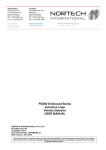
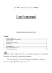
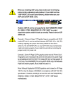
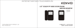
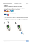
CCTV & Security Distributor
Waterproof Integrated
Access Controller
1
3
5
7
9
*
Water proof product series is RF integrated access controller. The
series supports EM, HID and Mifare cards according to difference
models. It is the most advanced one-door controller at present. It
adopts metal case, practical keyboard and built-in microprocessor. It
can supply protection for 2000 users. Moreover, the device is
characterized by ultra low ultra-power consumption, lightened
keyboard, independent password, Wiegand output, output short-circuit
protection, door-magnet alarm, exit button, and door bell interface etc,
which can be applied in family, office room, residence community and
other public places.
2
4
6
8
0
#
The Front
4. Function Feature
The Back
1.1 Color: Silvery
1.2 Dimension: 120mm×58mm×22mm
User Manual
2. Important Notices
Failure to follow the instructions below may lead to the malfunction of
the system, property damage and even physical injury.
JP1
7.10.1 Normal Mode (Default)
Press # to open door
Read card
Input old password #
Input new password #
Input again
7.12 User Modify Password by ID Number:
User modify password by ID number
Input ID number
Input new password #
Input old password #
Input again
Note: It is used to users who holds card or no card, if user password is
“1234”, it must be modified by card.
7.13 Open Door by Card
After present valid card, door will open.
Release alarm
It can release alarm
7.16.2 Close Alarm Sound
Release alarm
Read valid card
or
Input admin password
It can release alarm
Storage Capacity: 2000 users
Temperature: -25℃~60℃
Humidity: 10%~90%
4
6
7
8
9
*
0
Red Light
Flash slow
Green
Light
Buzzer
Success
7.4 Add User
Step 2
Open the case by upward against
the bottom case
Step 3
Please fix bottom case
on wall
Beep
On
Fail
Setup Status
Exit Edit
On
Flash Slow
7.4.1 Add Card continuously:
2
3
4
5
6
7
8
9
*
0
#
1
2
3
4
5
6
7
8
9
*
0
#
Step 4
Fix the front case on bottom case
Step 5
Fix the cases by screw
Mark
Color
Indicator Light
is Yellow
On
Beep
Off
Off
On
Alarm
Flash Fast
Off
Card NO. 2 +#
Press # to end
Note: When add card number automatically, user ID number will come
out automatically, the range will be 1-2000 and search from small to
large.
7.4.3 Appoint ID number to present and add card
ID NO.1+#
1
BELL_A
Pink
Another port of door bell
D0
Green
Weigand output wire D0
D1
White
Weigand output wire D1
BELL_B
3
4
Beep
5
6
7
ALARM
OPEN
D_IN
Alarm Sound
8.Instructions for Keypad
8.1 Not all readers are facilitated with keypad. The reader models
facilitated with keypad support 6-digit password.
8.2 The reader will transform 6-digit password into Wiegand 26 format
and send the data to controller.
8.3 The user should input the 2nd digit within 2s after inputting the
1st digit, otherwise the 1st digit will be deleted automatically and
the user has to input the password again.
8.4 If wrong number is input, the user can press the ESC key and reinput the password again.
8.5 After input password, please press “#” keypad, it means over.
8.6 When take it as reader, please set Safe Mode as default.
9
10
DC12V
Gray
Yellow
Warner negative (alarm positive
connect with +12V)
One port of exit button (the another
port connect with GND)
One port of door magnet (the another
Brown port connect with GND)
Red
Power supply 9-28V input(DC input +)
GND
Black
Power supply 9-28V input (DC input-)
NO
Blue
Relay normal open (connect with failsecure lock)
Read card
ID NO.1+#
Press # to end
Setup card or password to open door
Press 3
Press 2
Confirm #
Setup open door time
Press 4
Press 0-99
Confirm #
Note: Open Time range: 0-99s, default is 5s.
7.8 Alarm Time Setup:
Setup alarm time
Press 5
Press 0-3
Confirm #
Note: Alarm Time Range: 0-3 min, default is 1 min.
7.9 Door-magnet Alarm Setup:
7.9.1 Shield door-magnet alarm function (default):
Shield door-magnet alarm
Press 6
Press 0
Confirm #
Press 6
Press 1
Confirm #
There are two situations after start the function:
7.9.2.1 If open door and do not close normally, after 1 min, the built-in
beeper send alarm sound and close door or close directly after 1 min.
7.9.2.2 User open lock, door open after 20s, or door is opened by
force. The external and built-in beeper alarm simultaneously.
Press # to confirm delete all
7.6 Open Door Way Setup: Set the way of open door.
7.6.1 Open by Card:
Press 3
7.6.3 Open by Card or Password: (Default)
Start door-magnet alarm
ID NO.2+#
Delete all
Press 20000
Confirm #
7.9.2 Start Door-magnet Alarm Function:
7.10 Safe Mode Setup
Setup card to open door
Press 0
Confirm #
7.4.4 Appoint ID number and add card number:
10.2 Power Supply Wiring Diagram
10.1 General Power Supply Wiring Diagram
One port of door bell
Light
Blue
2
Press # to end
Card NO. 2 +#
7.5.4 Delete All
Press # to end
ID NO.2+#
10.Wiring Diagram
Function
Card NO. 1 +#
Press 2
BELLA
Wire No
Press # to end
Read card 2
7.5.3 Appoint ID number to Delete
Appoint ID number and read card to add
Appoint ID number and read card to add
Beep
Off
Open Lock
Press # to end
Read card 2
Appoint card number to add
Card NO. 1 +#
Read card
Press 1
Press 1
Read card 1
Press 2
Read card 1
7.4.2 Appoint to Add Card:
1
ID NO.2+# Password+#
Read card to delete
Press 2
Press 1
7.7 The Time of Lock Open Setup:
ID NO.3+# Password+#
Press # to end
Note: It is used in no card user, password have no relative with card,
input digital is 4, but can not be “1234”.
7.5 Delete User
7.5.1 Delete Card
Add card continuously
Press 1
Press 3
7.5.2 Appoint Card Number to Delete
Appoint card number to delete
Power (DC 12V)
Beep Beep
Beep
On
Input again #
ID NO.1+# Password+#
Press 1
Note: Administrator password is 6 – 8 digital any number, please
remember it.
Off
Press # to open door
Go to Edit
Input new password #
#
8
Release alarm
Modify administrator Password
Memo
Beep
Off
Press # to confirm
Input admin password
7.3 Modify Administrator Password:
Press 0
Setup card + password to open door
Press # to end
Appoint ID number and card number to add
Administrator default password is: 999999
9.Wiring Nomination
Button
After present valid card and input correct password, door will open.
7.16 Release Alarm Operation
7.16.1 External alarm and built-in beeper alarm simultaneously.
Release alarm
Read valid card
or
Input admin password
3
5
Card NO. 2 +#
BELLA
-
+12V
Pink
Door Bell
BELLA Light Blue
GND
D0
Green
D0
D1
White
D1
ALARM
Gray
OPEN
D_IN
Yellow
Brown
+12V
Red
GND
Black
NO
Blue
COM
Purple
NC
Orange
IR
(NO\NC)
Exit Button
Door-magnet
Fail-secure
D0
Pink
Light
Blue
Green
D1
White
BELLA
ALARM Gray
OPEN Yellow
D_IN
Brown
+12V
Red
GND
Black
NO
Blue
COM
Purple
NC
Orange
10.3 Wiring Diagram Spacification
+12V
Door Bell
GND
D0
IR
(NO\NC)
D1
Fail-safe
+
-
Exit Button
Door-magnet
V+
VNO
COM
NC
Fail-secure
V+
V-
Power
Press 7
Press 1
Confirm #
It means that user present invalid card or input wrong password for ten
times continuously within 10 minutes, external warner and built-in
beeper will alarm simultaneously.
7.11 User Operation
7.11.1 User modify password by card
User modify password by card
2
Card NO. 1 +#
NO COM NC +12V GND PUSH
Setup alarm mode
Input user password
1
Waterproof Integrated Access Controller
It means that user present invalid card or input wrong password for ten
times continuously within 10 minutes, system will be locked for 10
minutes.
7.10.3 Alarm Mode:
Read card
Press *
ID NO.2+#
Note: Input ID number is 1-4 digital, the range is 1-2000, such as 1,01,
001, 0001 are mean ID number 1.
Adding card user has a default password “1234”, but this password can
not open door, It will be used when modify password only.
7.4.5 Appoint ID number and add password
Enter administrator operation
Access Controller
Confirm #
Operation
status
Standby
Open door by card + password
Press 1
Working Voltage: DC9-28V
Quiescent Current: ≤30mA
Read Distance: 3~8cm
7.17 Audible and Visual Indication
After input correct password, door will open.
7.15 Open Door by Card + Password
Setup lock mode
Press *
Input user password
Step 1
Please turn on the bottom screw
Press 1
ID NO.1+#
Access Controller
Confirm #
7.1 Restore Factory Setting:
After device power off, please press # button and do not release it, then
power on, if device beep, please release the button. Now finish.
Note: The operation of restore factory setting will not delete user
information.
7.2 Enter Administrator Operation Status:
6. Installation Instruction
7.6.2 Open by Card + Password:
Appoint ID number and card number to add
7. Manager Operation
Waterproof Integrated Access Controller
Press 0
7.10.2 Lock Mode :
Press *
JP1
7.14 Open Door by Password
Open door by password
Setup normal mode
Press 7
JP1
2.7 When RS485 mode is applied, a highway can connect maximally 32
controllers with identification address differs from each other.
http://www.provisual.com
Press 7
JP1
Supper Low Consumption: Standby current less than 30mA.
Lighted Keyboard: User can operate keyboard without light.
User Capacity: It supports 2000 users.
Independent Password: User can open door by password without card.
Password Modify: User can modify password by himself.
High Speed Search: After read card, door can open within 0.1s.
Output Short Circuit Protection: When lock or alarm output short circuit,
output will be closed within100μS automatically.
Wiegand Output: It outputs W26 card number or WG 4 keypad number.
Delete Card: If user loss the card, manager can delete the card by
keypad to avoid any safety loophole.
Dismiss Alarm: When dismissed abnormally, device buzzer will alarm.
Door Bell keypad: Keypad is isolated with circuit, it can connect with
door bell.
Output Short Circuit Protection: ≤100μS
Open Time: 0-99 (can be adjusted)
5. Parameter
232 485
Read the manual before usage and keep for
future reference.
232 485
AC920P
2.1 Connection and operation on any components or the controller with power on
is strictly prohibited.
2.2 Connect the system according to the instructions described in this manual.
2.3 The RS232 cable connected to the computer should be no more than 15 meters.
2.4 The RS485 cable connected to the computer should be no more than 1200m.
2.5 Please use the specified power supply.
2.6 The communication mode between the controller and computer should be
either RS232 or RS485.
232 485
*
2
4
6
8
0
#
232 485
1
3
5
7
9
Lock Output: ≤3A
Alarm Ouput: ≤20A
3. Product Introduction
+
1. Product Appearance
Connection Device
Cable Type
Main Point
Power Supply – Int
-egrated Access
Controller
RVV2*1.0
Distance <100M
Integrated Access
Controller
- Controller
RVV4*0.5
Distance 60m, can
not over 100m
Integrated Access
Controller - Lock
RVV4*1.0(with doormagnet)
Distance <150M
RVV2*0.5
Distance <150-200M
RVV2*1.0
Distance <200M
Integrated Access
Controller - Exit
Button
Integrated Access
Controller - IR
Warner
+
-
V+
VNO
COM
NC
V+
V-
Fail-safe
11
COM
12
NC
Purple
Relay common port (connect with
power GND)
Orange Relay normal close (connect with failsafe lock)
Sustained Effort for the Better