1
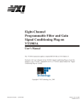
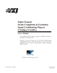
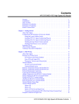
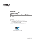
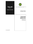
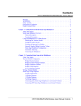
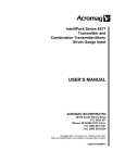
bus
Four-Channel Transient Strain Signal
Conditioning Plug-on
VT1511A
User’s Manual
The VT1511A manual also applies to Agilent/HP E1413B as Agilent/HP E1413 Option 21.
Enclosed is the User’s Manual for the VT1511A Signal Conditioning Plug-on. Insert this
manual in your VT1413C or Agilent/HP E1313 manual behind the “Signal Conditioning
Plug-ons” divider.
The VT1511A, Four-Channel Transient Strain SCP can be used with the VT1413C, VT1415A
and the Agilent/HP E1313A and E1413B versions, but not with the Agilent/HP E1413A.
Copyright © VXI Technology, Inc., 2003
Manual Part Number: 82-0085-000
Printed: July 9, 2003
Printed in U.S.A
VT1511A
Four-Channel Transient Strain
Signal Conditioning Plug-on
Introduction
VT1511A is a double wide (i.e., takes the space of these two adjacent slots: 0-1,
2-3, 4-5, or 6-7) Signal Conditioning Plug-on (SCP) that provides 4 channels of
strain measurements for the VT1413C High Speed A/D Module. The SCP provides
4 channels of Strain Completion Circuitry and Excitation Voltages, a
programmable filter, and makes the strain measurements on 4 channels using the
Sample and Hold method. The SCP provides the strain completion circuitry and the
Sample and Hold circuitry. The SCP can be wired for measuring the Excitation
Voltage at the bridge connection (Remote Sense) or locally on the Terminal
Module.
Note The VT1511A, Four-Channel Transient Strain SCP can be used with the
VT1413C, VT1415A and the Agilent/HP E1313A and E1413B versions, but not
with the Agilent/HP E1413A.
About This Manual
Except where noted, references to the VT1413C also aply to the VT1415C and
Agilent/HP E1313. This manual shows how to connect to the Terminal Module for
sample/hold strain measurements, and also shows how to control the Option 21
Signal Conditioning Plug-on (SCP) using SCPI commands and Register-Based
commands. The following also explains the capabilities of the SCP and gives the
specifications. The manual contents is:
·
·
·
·
·
·
·
Introduction
VT1511A Operation . . . . . . . . . . . . . . . . . . . . . . . . . . . . . . 4
Selecting the 1/4 Bridge and 120/350 Ohm Jumpers . . . . . . . . . . . . . 7
Connecting To The Terminal Module . . . . . . . . . . . . . . . . . . . . . 8
Programming With SCPI Commands . . . . . . . . . . . . . . . . . . . . 14
Using External Excitation Voltages . . . . . . . . . . . . . . . . . . . . . 20
Register-Based Programming . . . . . . . . . . . . . . . . . . . . . . . . 22
Specifications . . . . . . . . . . . . . . . . . . . . . . . . . . . . . . . . . 24
VT1511A Transient Strain SCP 3
VT1511A Operation
There are two circuits on the VT1511A SCP, one circuit provides the Bridge
Excitation Voltage and Bridge Completion circuitry, and the other circuit provides
the sample and hold measurement circuitry.
The completion circuitry can output a Bridge Excitation voltage of 0 V, 1 V, 2 V,
5 V or 10 V on each channel.
Note
The 10 V Excitation level can not be used with a 120 W Full Bridge configuration.
This low impedance bridge configuration draws too much current from the
excitation supply at 10 V (>50 mA supply limit).
The measurement circuitry provides the measurement path to the VT1413C for both
the excitation voltage and the output voltage of the strain gage bridge. The VT1413C
measures the excitation voltage during calibration and measures the bridge output
voltage during a measurement cycle.
The measurement circuitry samples all channels simultaneously and thus reduces the
skew introduced by scanning. The amount of skew removed depends on the cutoff
frequency setting of the lowpass Filter (see next paragraph). When reducing the filter
bandwidth, the propagation delay increases between the channels which causes a
larger delay between channels programmed to the same bandwidth (see specifications
for delay values). The circuitry provides a voltage gain of 0.5, 8, 64 or 512 for each
bridge output measurement channel.
The SCP also has a lowpass Filter on each bridge output measurement channel. The
filter is a 6th order Bessel Active RC filter used to provide alias protection and noise
reduction. The filter cutoff frequencies are 1 kHz, 500 Hz, 250 Hz, 100 Hz and 15 Hz.
There are two ways the VT1413C can measure the excitation voltage while calibrating
the SCP. One way measures the voltages at the bridge connections (remote sense) and
the other way measure the voltage locally at the connections in the Terminal Module.
The remote sense is more accurate, but requires extra wiring to the bridge.
Figures 1, 2 and 3 show examples of a typical 1/4 Bridge, 1/2 Bridge, and Full
Bridge strain gage measurement, respectively. The figures also show the
calibration shunt resistor connects to the bridge. When shunt calibration is enabled,
the shunt resistor is switched in parallel to one leg of the bridge. This causes a
change in the bridge output voltage. Use it to check the bridge wiring.
4 VT1511A Transient Strain SCP
VT1511A Operation
Figure 1. Typical 1/4 Bridge Measurement
Figure 2. Typical 1/2 Bridge Measurement
VT1511A Operation
VT1511A Transient Strain SCP 5
Figure 3. Typical Full Bridge Measurement
6 VT1511A Transient Strain SCP
VT1511A Operation
Selecting the 1/4 Bridge and 120/350 Ohm Jumpers
Figure 4 shows how to select the 1/4 Bridge Jumper and how to select for either
120 W or 350 W bridges.
Figure 4. Selecting the 1/4 Bridge and 120/350 Ohm Jumpers
Selecting the 1/4 Bridge and 120/350 Ohm Jumpers
VT1511A Transient Strain SCP 7
Connecting To The Terminal Module
This section shows how to make 1/4, 1/2. and Full Bridge strain gage connections
to the Terminal Module.
The SCP connections for the Terminal Modules are shown on the stick-on labels
that came with the SCP. Use the appropriate label for the type of Terminal Module
you have. The connections and appropriate stickers are as follows:
· For VT1413C and above Terminal Modules, use stickers for VT1510A
SCPs. The connections are shown in Figure 5.
· For Agilent/HP E1313 Terminal Moduless, use stickers for VT1510A
SCPs. The connections are shown in Figures 6 and 7.
· For Agilent/HP E1413B and below Terminal Modules, use stickers for
Agilent/HP E1413 Option 20 SCPs. The connections are shown in
Figure 8.
Figure 5 VT1511A C-Size Terminal Module Connections
8 VT1511A Transient Strain SCP
Connecting To The Terminal Module
Figure 6 VT1511A B-size Terminal Module Connections (Ch 00-31)
Figure 7 VT1511A B-size Terminal Module Connections (Ch 32-63)
Figure 8 Agilent/HP E1413 Option 21 Terminal Module Connections
Connecting To The Terminal Module
VT1511A Transient Strain SCP 9
Wiring the
Terminal Module
· See “Attaching and Wiring the Terminal Module” in the VT1413C
User’s Manual to wire the strain gages to the Terminal Module.
· For accurate measurements, use a twisted shielded cable for the strain gage
connections. Connect the shield to the specimen and to the guard (G) terminal
on the Terminal Module.
Note
The following figures in this section show the connections using SCP 0 as the
Strain SCP and SCP 1 as the Direct Input SCP. Use the same technique using
other SCPs and other channel numbers.
For example, for a Channel 00 H and L connection on SCP 0, connect to H and
L on Channel 57 for SCP 7. See “Opening and Wiring the Terminal Module” in
the VT1413C User’s Manual to wire the strain gages to the Terminal Module.
1/4 Bridge
Connections
Use Figure 9 for 1/4 Bridge connections to the Terminal Module. Install or make
sure the 1/4 Bridge Jumper(s) is installed in the 1/4 Bridge configuration for all
channels that are to make 1/4 Bridge measurements (see Figure 4).
Transient Strain SCP (0-1)
Note
The optional Shunt
Resistor connection
is shown by the
dashed lines
Sample
Shielded Cable
Figure 9. Typical 1/4 Bridge Connections
10 VT1511A Transient Strain SCP
Connecting To The Terminal Module
1/2 Bridge
Connections
Use Figure 10 for 1/2 Bridge connections to the Terminal Module. Remove or be
sure the 1/4 Bridge Jumper(s) is not installed in the 1/4 Bridge configuration for all
channels that are to make 1/2 Bridge measurements (see Figure 4).
Figure 10. Typical 1/2 Bridge Connections
Connecting To The Terminal Module
VT1511A Transient Strain SCP 11
Full Bridge
Connections
Use Figures 11 and 12 for Full Bridge connections to the Terminal Module.
Remove or be sure the 1/4 Bridge Jumper(s) is not installed in the 1/4 Bridge
configuration for all channels that are to make Full Bridge measurements (see
Figure 4).
Figure 11. Typical Full Bridge Connections
12 VT1511A Transient Strain SCP
Connecting To The Terminal Module
Figure 12. Typical Full Bridge Connections (Cont.)
Connecting To The Terminal Module
VT1511A Transient Strain SCP 13
Programming With SCPI Commands
The following SCPI commands verify the SCP types installed in the VT1413C and
how to program the VT1413C for strain measurements using VT1511A SCPs. The
commands listed in this section are below and also in Chapter 5 of the VT1413C
User’s Manual.
SCPI Commands
Used
The following table lists all commands used in this section of the manual.
Command
Description
CALibration:TARE (@<ch_list>)
calibrates SCP on specified channels
CALibration:TARE?
returns calibration value
INPut:FILTer[:LPASs]:FREQuency <cutoff_freq>,(@ch_list>)
selects the SCP’s low pass filter cufoff frequency
INPut:GAIN <chan_gain>5,(@<ch_list>)
selects the sample and hold gain
INPut:LOW FLOat | WVOLtage,(@<ch_list>)
selects the sample & hold amplifier input connection
OUTPut:VOLTage:AMPLitude <amplitude>,(@ch_list>)
selects the excitation voltage value
[SENSe:]FUNCtion:STRain:FBPoisson [<range>,](@<ch_list>)
selects the range for the full bridge bending poisson EU
conversion
[SENSe:[FUNCtion:STRain[:QUARter] [<range>,](@<ch_list>)
selects the range for quarter bridge EU conversion
[SENSe:]STRain:GFACtor <gage_factor>,(@<ch_list>)
selects the strain gage factor
[SENSe:]STRain:POISson <poisson_ratio>,(@<ch_list>)
selects the poisson ratio
SYSTem:CTYPe? (@<channel>)
returns the SCP type
Checking the ID of
the SCP
Use the “SYSTem:CTYPe? (@<channel>)” command to verify the SCP type(s)
in the VT1413C.
· The channel parameter specifies a single channel in the channel range covered
by the SCP of interest. The first channel numbers for each of the SCP positions
are: 0, 16, 32 and 48, if all SCPs are VT1511A SCPs.
The value returned for the SCP in an Agilent/HP E1413B is:
HEWLETT-PACKARD, E1413 Opt 21 4-Ch S/H-Strain Bridge Completion SCP,,0
The value returned for the SCP in a VT1413C or Agilent/HP E1313A is:
HEWLETT-PACKARD, E1511 4-Ch S/H-Strain Bridge Completion SCP,,0
To determine the type of SCP installed on channels 0 through 7, send:
14 VT1511A Transient Strain SCP
SYST:CTYP? (@100)
query SCP type @ ch 0
enter statement here
enter response string
Programming With SCPI Commands
Making 1/4 Bridge
Measurements
The following example shows how to make 1/4 Bridge measurements using
channels 0 through 3. Be sure to set the jumper for the 1/4 Bridge configuration (see
Figure 4).
Bridge is Unstrained The following commands select the excitation voltage and specifies the parameters
to convert strain gage readings for the specified channels. Do this when the bridge
is in the Unstrained configuration. The commands are separated into two parts. The
first part configures and calibrates the excitation/completion circuitry. The second
part configures the module for strain measurements. Execute these commands
when the bridge is in the Unstrained configuration.
Setup and Calibrate Excitation/Completion Circuitry
OUTP:VOLT:AMPL 1,(@100:103)
select the excitation voltage value
for channels 0 - 3 (default is 0 V)
INP:LOW WVOL,(@100:103)
selects the Wagner voltage input
INP:FILT:FREQ 1000,(@100:103)
selects the sample and hold
lowpass filter frequency (default is
15 Hz)
INP:GAIN 8,(@100:103)
selects the gain of the sample and
hold circuitry (default is 0.5)
CAL:TARE (@100:103)
measure the unstrained voltage on
channels 0-3
CAL:TARE?
to return the success flag from the
CAL:TARE operation
enter CAL:TARE query
wait until success flag from
CAL:TARE operation is returned
Configure the Measurement
STR:GFAC 2,(@100:103)
specifies the gage factor on
channels 0-3 (selected factor 2 is
the default value)
FUNC:STR:QUAR 1,(@100:103)
link channels 0-3 to EU conversion
for strain measurement (selected
1V range value is the default value)
Bridge is Strained When the bridge is in the Strained configuration and the measurements are to be
made, scan the selected channels and make the measurements. Use the VT1413C’s
INITiate and TRIGger commands to make the strain measurement. You must
define what triggers, etc., to use to make the measurements (see the “VT1413C
User’s Manual” for information).
Programming With SCPI Commands
VT1511A Transient Strain SCP 15
Making Full Bending
Poisson Bridge
Measurements
The following example shows how to make Full Bridge Bending Poisson Bridge
measurements using channels 0 through 3. Be sure to set the jumper for the 1/2 or
Full Bridge configuration (see Figure 4).
Bridge is Unstrained The following commands select the excitation voltage and specifies the parameters
to convert strain gage readings for the specified channels. Do this when the bridge
is in the Unstrained configuration. The commands are separated into two parts. The
first part configures and calibrates the excitation/completion circuitry. The second
part configures the module for strain measurements. Execute these commands
when the bridge is in the Unstrained configuration.
Setup and Calibrate Excitation/Completion Circuitry
OUTP:VOLT:AMPL 1,(@100:103)
select the excitation voltage value
for channels 0-3 (default is 0 V)
INP:LOW FLO,(@100:103)
selects the floating input
INP:FILT:FREQ 1000,(@100:103)
selects the sample and hold
lowpass filter frequency (default is
15 Hz)
INP:GAIN 8,(@100:103)
selects the gain of the sample and
hold circuitry (default is 0.5)
CAL:TARE (@100:103)
measure the unstrained voltage on
channels 0-3
CAL:TARE?
to return the success flag from the
CAL:TARE operation
enter CAL:TARE query
wait until success flag from
CAL:TARE operation is returned
Configure the Measurement
STR:GFAC 2,(@100:103)
specifies the gage factor on
channels 0-3 (selected factor 2 is
the default value)
STR:POIS .3,(@100:103)
set Poisson ratio for EU
conversion; selected value is 0.3
(default value)
FUNC:STR:FBP 1,(@100:103)
link channel 0-3 to EU conversion
for strain measurement; selected
voltage range is 1 V
Bridge is Strained When the bridge is in the Strained configuration and the measurements are to be
made, scan the selected channels and make the measurements. Use the VT1413C’s
INITiate and TRIGger commands to make the strain measurement. You must
define what triggers, etc., to use to make the measurements (see the “VT1413C
User’s Manual” for information).
16 VT1511A Transient Strain SCP
Programming With SCPI Commands
Comments
The following explains the commands used in strain measurements.
How to Link EU The following explains the commands that link the strain EU conversion with the
Conversions to specified channels. The commands tell the VT1413C to use the EU conversion for
Channels strain measurements. The VT1413C performs the appropriate EU conversion (e.g.,
1/4 Bridge measurements) depending on the command used. Thus, each bridge
configuration has its own command with the command used for the 1/4 Bridge
configuration as the default value. (See “Linking Channels with EU Conversion” in
Chapter 3 of the VT1413C User’s Manual.)
The syntax of a typical command is:
[SENse:]FUNCtion:STRain:HBENding [<range>,](@<ch_list>)
where <range>> is the voltage range of the VT1413C (default value or no specified
parameter is AUTO) and <ch_list> specifies the channels.
The different bridge types and corresponding EU to Channels Linking commands
are in the following table.
Bridge Type
Command
Full Bending Bridge [SENse:]FUNCtion:STRain:FBENding
Full Bending Poisson Bridge [SENse:]FUNCtion:STRain:FBPoisson
Full Poisson Bridge [SENse:]FUNCtion:STRain:FPOisson
1/2 Bending Bridge [SENse:]FUNCtion:STRain:HBENding
1/2 Poisson Bridge [SENse:]FUNCtion:STRain:HPOisson
1/4 Bridge [SENse:]FUNCtion:STRain[:QUARter]
Notes
1. The strain readings from the VT1413C are output as micro strain (µe) units.
2. Because of the number of possible strain gage configurations, the driver
must generate any Strain EU conversion tables and download them to the
instrument when INITiate is executed. This can cause the time to complete
the INIT command to exceed 1 minute.
Purpose of Channel The CALibration:TARE command measures the voltage across the bridge to
Tare Calibration determine the unstrained voltage value of the bridge. This corrects for the offset
(CAL:TARE) voltage across the bridge when in the Unstrained configuration.
The command automatically executes the CAL? command and thus calibrates the
internal excitation supply.
Programming With SCPI Commands
VT1511A Transient Strain SCP 17
The VT1413C uses the unstrained reading (i.e., offset voltage) in conjunction with
the strain gage factor (see “Purpose of the Strain Gage Factor Command
(STR:GFAC)” below) to calculate the strain measurements. You normally
perform both operations before making the actual strain measurements.
Instead of using CAL:TARE, you can use the [SENSe:]STRain:UNSTrained
command to enter the unstrained voltage. In this case you must measure and enter
the offset voltage of the bridge, when the bridge is Unstrained. The command
syntax is:
[SENSe:]STRain:UNSTrained <unstrained_v>,(@<ch_list>)
where <unstrained_v> is the voltage value of the bridge in the unstrained position
(default is 0V) and <ch_list> specifies the channels to be measured.
Purpose of the Strain The [SENse:]STRain:GFACtor command specifies the gage factor to be used by the
Gage Factor Command VT1413C to calculate the strain measurements. The default value of the command is a
(STR:GFAC) factor of 2. The command syntax is:
[SENse:]STRain:GFACtor <gage_factor>,(@<ch_list>)
where <gage_factor> is the gage factor value (default is 2) and <ch_list> specifies
the channels to be measured.
Purpose of the Poisson The [SENse:]STRain:POISson command sets the Poisson ratio to be used by the
Ratio Command VT1413C for EU conversion of strain values measured (see “Linking Channels with EU
(STR:POIS) Conversion” in Chapter 3 of the VT1413C User’s Manual). This command is only
needed if making Poisson strain measurements. It is not needed for making 1/4 Bridge, or
1/2 or Full Bridge Bending measurements. The default value of the command is .3. The
command syntax is:
[SENse:]STRain:POISson <poisson_ratio>,(@<ch_list>)
where <poisson_ratio> is the Poisson ratio (default is 2) and <ch_list> specifies the
channels to be measured.
Connecting the Sample For 1/4 and 1/2 Bridge configurations, the low input of the sample and hold input
and Hold Amplifier amplifier should be connected to the negative side of the internal bridge connection on
Input (INPut:LOW) the SCP itself. This is done by a switch on the SCP which provides the Wagner voltage
for the bridge (see Figures 1 and 2).
For Full Bridge configuration, the low input of the sample and hold amplifier
should be externally connected to the negative side of the bridge. The amplifier
input must not be connected to the internal bridge (see Figure 3).
Use the following command for either configuration:
INPut:LOW <volt_type>,<@ch_list>
18 VT1511A Transient Strain SCP
Programming With SCPI Commands
where <volt_type> can be either FLOat for a floating input (Full Bridge
configuration) or WVoltage for a Wagner Voltage connection (1/4 and 1/2 Bridge
configurations). respectively, and <@ch_list> specifies the channels.
Using The Shunt Resistor
To check if the bridge is operational, you can add a 29.4 kW Shunt resistor across
one leg of the bridge, as illustrated in Figure 13. A FET switch adds or removes the
resistor. When the resistor is added, it changes the unstrained offset voltage on the
bridge.
The resistor can only affect the bridge balance as long as you follow the
connections shown in the dotted lines in Figures 1, 2 and 3, or as shown in
Figure 13. Use the OUTPut:SHUNt command to add or remove the resistor from
the bridge. The syntax of the command is:
OUTPut:SHUNt 1 | 0 | ON | OFF
+
+
1/4 Bridge
Strain
Gage
350W
RB
RS
120W
X01
Strain
Gage
RB
X02
X03
Bridge
Completion
Full Bridge
Strain
Gage
X04
Strain
Gage
29.4kW
Strain
Gage
RS
X01
120W
X02
X03
Bridge
Completion
X04
29.4kW
Shunt
Shunt
FET
Switch
Current Flow
350W
Current Flow
FET
Switch
+
1/2 Bridge
Strain
Gage
RB
350W
X01
120W
X02
X03
Bridge
Completion
Strain
Gage
RS
Note
The current must flow into
the Shunt Resistor,
as shown by the arrows
X04
29.4kW
Shunt
Current Flow
FET
Switch
OUTPut:SHUNt ON
Figure 13. Adding the Shunt Resistor
Using The Shunt Resistor
VT1511A Transient Strain SCP 19
Using External Excitation Voltages
You can use your own external excitation voltage instead of using the internal
voltage of the SCP. If using an external voltage, you must:
· use your own bridge completion circuitry
· isolate the internal excitation supply from the bridge
· enter the value of the excitation voltage into the VT1413C so it can
make the correct EU conversions for strain measurements
Connecting the
External Supply
Use Figure 14 to connect the external supply to the Terminal Module. Be sure not
to connect the external excitation voltage to the “E+” and “E-” terminals.
Enter Excitation
Voltage Value
Use the [SENSe:]STRain:EXCitation command to enter the value of the
external excitation voltage. The syntax for the command is:
[SENSe:]STRain:EXCitation <excite_v>,(@<ch_list>)
where <excite_v> is the value of the external excitation voltage and <ch_list>
specifies the measurement channels of the SCP.
The default value of the excitation voltage is 3.9 V, the minimum allowable voltage
value that can be entered is 0.01 V, and the maximum value that can be entered is
99. However, the maximum allowable input voltage of the Sample and Hold Input
Amplifier is 16V which may limit the maximum Excitaion Voltage to 16 V.
20 VT1511A Transient Strain SCP
Using External Excitation Voltages
Transient Strain SCP (0-1)
Poisson Full Bridge
Top Sample
Note
The optional Shunt
Resistor connection
is shown by the
dashed lines
Bottom Sample
Shield
[SENSe:]STRain:EXCitation <excite_v>,(@<ch_list>)
External Excitation Voltage
Figure 14. Connecting External Excitation Voltages
Using External Excitation Voltages
VT1511A Transient Strain SCP 21
Register-Based Programming
Appendix D of the VT1413C User’s Manual covers the Register-Based commands
shown below. You should read that appendix to become familiar with accessing
registers and executing Register-Based commands. This section relates those
commands to the parameter values that are specified for this SCP.
When Register Programming an SCP, most communication is through the Signal
Conditioning Bus. For that you will use the Register Commands:
SCPWRITE <regaddr> <regvalue>
and
SCPREAD? <regaddr>
Read (returned value)
Write (<regvalue>)
SCP Register*
<regaddr> Value
Whole SCP Reg 0
00ppp000000 2
Whole SCP Reg 1
00ppp000001 2
Channel Reg 0
01pppccc0002
Channel Gain (Sample and Hold channels):
(FFFF16=0.5, FFF116=8, FFF216=64, FFF316=512)
Channel Gain (direct channels): 000016=1
Channel Reg 1
01pppccc0012
Channel Frequency: (XXX016=15Hz, XXX116=100Hz,
XXX216=250Hz, XXX316=500Hz, XXX416=1kHz)
Channel Reg 2
01pppccc0102
SCP ID (source) - Opt 21: (610016)
SCP Gain Scale - (XXX316)
Excitation, Wagner Voltage, and Shunt Cal Resistor:
Data format is XEVVVVWS2 where:
X=don’t care
E=enable
excitation voltage 1=on, 0=off
V=Excit. V bits, 00012=1V, 00102=2V, 01002=5V, 10002=10V
W=Wagner Voltage to LO, 1=connected, 0=disconnected
S=Shunt Cal Resistor, 1=in circuit, 0=out
X=don’t care
ppp=Plug-on
ccc=SCP channel
* see the SCPWRITE and SCPREAD? commands in Appendix D to learn more on how
to read the SCP regisaters.
Checking the ID of
the SCP
22 VT1511A Transient Strain SCP
To query an SCP for its ID value, write the following value to Parameter Register 1:
( SCP number ) ´ 4016
Then write the opcode for SCPREAD? (080016) to the Command Register. The ID
value will be written to the Response Register. Read the Response Register for the
value.
Register-Based Programming
Setting the Filter
Cutoff Frequency
To set the filter cutoff frequency for an SCP channel, write the following SCP
channel address to Parameter Register 1:
20016 + (SCP number) x 4016 + (SCP channel number) x 816 + 216
Write one of the following cutoff values to Parameter Register 2:
000016 for 15 Hz, 000116 for 100 Hz, 000216 for 250 Hz,
000316 for 500 Hz, 000416 for 1 kHz
Then write the opcode for SCBWRITE (0810 16) to the Command Register.
Setting the Channel
Gain
To set the amplifier gain for an SCP channel, write the following SCP channel
address to Parameter Register 1:
20016 + (SCP number) x 4016 + (SCP channel number) x 816 + 116
Write one of the following gain values to Parameter Register 2:
FFFF16 for 0.5, FFF116 for 8, FFF216 for 64, FFF316 for 512
Then write the opcode for SCBWRITE (0810 16) to the Command Register.
Setting the Channel
Excitation Voltage
To set the excitation voltage for an SCP channel, write the following SCP channel
address to Parameter Register 1:
20016 + (SCP number) x 4016 + (SCP channel number) x 816
Write one of the following values to Parameter Register 2:
FF0016 for 0 V, FF4416 for 1 V, FF4816 for 2 V, FF5016 for 5 V, or
FF6016 for 10 V
Then write the opcode for SCBWRITE (081016) to the Command Register. The
values above will set the stated excitation values as well as the default state for the
channel’s Wagner Ground and Cal Shunt Resistor (both disconnected).
Controlling Wagner
Ground
To connect the Wagner Voltage to the LO terminal, simply add the value 000216 to
the Excitation Voltage code sent in the procedure above.
Controlling Cal
Shunt Resistors
To shunt the bridge with the Cal Resistor, add the value 000116 to the Excitation
Voltage code sent in the procedure above.
Register-Based Programming
VT1511A Transient Strain SCP 23
Specifications
SCP Current Requirements (Amps)
5Vmax
24Vtyp 24Vmax -24Vtyp
0.55
0.014
0.015
0.013
-24Vmax
0.015
Voltage Measurements
Accuracy: Gain of X0.5
Range
±FS
Gain
error
Offset
error
Noise
3 sigma
125 mV
0.02
488 µV
1.5 mV
0.5 mV
0.02
488 µV
1.5 mV
2.0 V
0.02
488 µV
1.5 mV
8.0 V
0.02
488 µV
1.5 mV
Temperature coefficients
Gain: 10 ppm/°C (after *CAL)
Offset: add tempco error to above table
Temp
Tempco
(0 - 30)
0 µV/°C
(30 - 55)
0.75 µV/°C
Accuracy: Gain of X8
Range
±FS
Gain
error
Offset
error
Noise
3 sigma
7.8 mV
0.02
30.5 µV
95 µV
31.25 mV
0.02
30.5 µV
95 µV
125 mV
0.02
30.5 µV
95 µV
0.5 V
0.02
30.5 µV
95 µV
Temperature coefficients
Gain: 10 ppm/°C (after *CAL)
Offset: add tempco error to above table
24 VT1511A Transient Strain SCP
Temp
Tempco
(0 - 30)
0 µV/°C
(30 - 55)
0.75 µV/°C
Specifications
Accuracy: Gain of X64
Range
±FS
Gain
error
Offset
error
Noise
3 sigma
3.9 mV
0.02
15.0 µV
12 µV
15.6 mV
0.02
15.0 µV
12 µV
62.5 mV
0.02
15.0 µV
12 µV
Temperature coefficients
Gain: 10 ppm/°C (after *CAL)
Offset: add tempco error to above table
Temp
Tempco
(0 - 40)
0.14 µV/°C
(40 - 55)
0.38 µV/°C
Accuracy: Gain of X512
Range
±FS
Gain
error
Offset
error
Noise
3 sigma
7.81 mV
0.04
15 µV
2 µV
Temperature coefficients
Gain: 10 ppm/°C (after *CAL)
Offset: add tempco error to above table
Specifications
Temp
Tempco
(0 - 40)
0.14 µV/°C
(40 - 55)
0.38 µV/°C
VT1511A Transient Strain SCP 25
Filter Characteristics
Normal mode rejection:
15 Hz lowpass filter (6 pole Bessel)
15 Hz -3 dB
50 Hz >33 dB
60 Hz >43 dB
100 Hz lowpass filter (6 pole Bessel)
100 Hz -3 dB
400 Hz > 43 dB
250 Hz lowpass filter (6 pole Bessel)
250 Hz -3 dB
1000 Hz >43 dB
500 Hz lowpass filter (6 pole Bessel)
500 Hz -3 dB
2000 Hz >43 dB
1000 Hz lowpass filter (6 pole Bessel)
1000 Hz -3 dB
4000 Hz >43 dB
Sample time skew between channels:
Because the lowpass filter precedes the sample and hold,
the interchannel sample time skew is primarily determined
by the matching of the filter propagation delay times. The
table below lists the propagation delay for a step function
input (measured at 50% of the final value) for each filter
setting, as well as the matching between channels
programmed to the same filter setting.
Bandwidth
Step Propagation Delay
(nominal)
Delay Matching
(± from nominal)
1 kHz
427.5 µs
10 µs
500 Hz
854.9 µsec
20 µs
250 Hz
1.710 ms
40 µs
100 Hz
4.275 ms
100 µs
15 Hz
28.50 ms
670 µs
Maximum filter overshoot:
< 1% of input step size
26 VT1511A Transient Strain SCP
Specifications
Common mode rejection (0 to 60 Hz):
X0.5 gain > 60 dB
X8 gain >78 dB
X64 gain >100 dB
X512 gain >100 dB
Maximum input voltage:
normal mode plus common mode
Operating: <±16 V peak
Damage level: >±42 V peak
Maximum common mode voltage:
Operating: <±16 V peak
Damage level: >±42 V peak
Crosstalk (referenced to input):
350 W source, DC to 1 kHz <80 dB
-20 log
(receiving channel input/source channel gain )
e.g., crosstalk from channel at gain of 0.5 to channel at
gain 512: <-80 dB -20 log (512/0.5) = -140 dB
Input impedance:
>100 MW
Maximum tare cal offset:
X0.5 gain ±25% of full scale
X8 gain ±90 mV
X64 gain ±95 mV
X512 gain ±95 mV
Specifications
VT1511A Transient Strain SCP 27
Sample and Hold Characteristics
Acquisition Time:
1 µs
Aperature Time:
2 ns
Aperature Delay:
35 ns + delay in skew specification
Aperature Jitter:
150 ps
Droop Rate:
1 Volt/s @ 50ºC. Typical is 2-3 mV/s @25ºC. This is
referenced to the SCP output so divide by SCP gain setting.
28 VT1511A Transient Strain SCP
Specifications
Specifications
VT1511A Transient Strain SCP 29
30 VT1511A Transient Strain SCP
Specifications
Specifications
VT1511A Transient Strain SCP 31
32 VT1511A Transient Strain SCP
Specifications
Specifications
VT1511A Transient Strain SCP 33
34 VT1511A Transient Strain SCP
Specifications