1
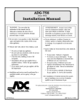
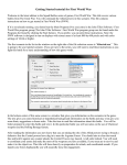
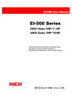
Wireless Security & Safety System
WA-1100-K
OWNER’S MANUAL
Table of Contents
Introduction…………………………………………………………………………….…... 3
System Package…………………………………………………………….…. 3
Optional Accessories…………………………………………………………... 3
Planning for Installation
Choosing a Location……………………………………………………….…... 4
Setting Alarm Zones…………………………………………………………..... 4
Installing the Back-up Battery………………………………………………..... 4
Powering the Main Console……………………………………………………. 4
Connecting the Telephone Line……………………………………………...… 5
Setting the Antenna…………………………………………………………..…. 5
Mounting the Main Console…………………………………………………..… 5
About Passwords…..…………………………………………………………..... 5
Others………………………………………………………………………….…. 5
Operation – Main Console……………………………………………………………….… 6
LCD Panel Illustration…………………………………………………………... 6
Function for Installer Menu…………………………………….………………. 7
System Option Menu…………………………………………………….……… 8
Sequence Programming Menu………………………………………………… 10
Replacement Menu……………………………………………………………… 11
Clear Menu………………………………………………………………………. 11
Function for Master Menu……………………………..…………….…………. 12
Check Function………………………………………………………………….. 13
Speed Dial Function…………………………………………………………….. 13
Arm or Disarm via the Telephone Line……………………………………….. 14
Auto Dialer Priority……………………………………………………………… 14
LCD Messages………………………………………………………………….. 15
24 Hour, Home & Away Functions………………………………………………………. 15
Remote Control Handset…………………………………………………………….……. 16
PIR Motion Detector……………………………………………………………………….. 17
Door/Window Detector……………………………………………………………………. 19
Mini Siren…………………………………………………………………………………… 22
Panic Watch Transmitter…………………………………………………………………. 23
Smoke Detector…………………………………………………………………………… 25
Door Keypad Detector……………………………………………………………………. 27
Gas Detector……………………………………………………………………………….. 28
Range Extender……………………………………………………………………………. 32
Summary of Program – Main Console………………………………………………….. 34
Summary of Sensors and Zone Settings……………………………………………….. 35
Specifications……………………………………………………………………………… 36
Installation Template……………………………………………………………………… 37
1
Important Safety Instructions
WARNING: TO REDUCE THE RISK OF FIRE OR ELECTRIC SHOCK, DO NOT
EXPOSE THIS APPLIANCE OR POWER ADAPTER TO WATER OR MOISTURE
•
•
•
•
•
•
•
•
•
Read Instructions – All the safety and operating instructions should be read before
operating this equipment. These instructions should be retained for future reference
Heed Warnings – All warnings on the equipment and in the operating instructions
should be adhered to. All instructions regarding care and operation of this equipment
should be followed.
Power Sources – Equipment should only be connected to the power supply specified
in the operating instructions or as marked on the equipment.
Grounding or Polarization – Take precautions that the equipment is properly
grounded. Take note that the power supply is fitted in the correct input jack ( marked
DC 12V ), and auxiliary units ( external siren and strobe light ) are fitted into the correct
external jack points.
Power-Cord Protection – Keep cable cords and plugs clear of other objects,
particularly at the point where they exit the equipment.
Cleaning – Clean the equipment by wiping with a soft cloth, ( do not use any abrasive
agents or water ).
Non-use Periods – Power cords should be unplugged from the outlet when left
unused for a long period of time.
Object and Liquid Entry – Take care not to drop objects or liquids on any part of the
equipment.
Damage Requiring Service – The alarm should be serviced by a qualified service
personnel when:
-
•
•
The power-supply cord or the plug has been damaged, or
Objects have fallen, or liquid has been spilled onto the equipment, or
The equipment has been exposed to rain, or
The equipment does not appear to operate normally or exhibits a marked
change in performance, or
The equipment has been dropped, and/or the enclosure has been damaged.
Servicing – Do not attempt to service the appliance beyond that described in the
operating instructions. All other servicing should be referred to a Qualified Distributor’s
Service Personnel.
System Maintenance – Under normal use your system requires virtually no
maintenance other than regular testing. It is recommended that you test your system
once a week, and replace the batteries at least once every 6 months (or as needed).
IMPORTANT NOTE: IF YOU RETURN TO YOUR PREMISES AND FIND THAT
THE ALARM IS IN PROGRESS, DO NOT ENTER, AS A FIRE OR AN INTRUDER
MAY BE PRESENT. GO TO A NEIGHBOR AND CONTACT THE RELEVANT
LOCAL AUTHORITIES FROM THERE.
2
Introduction
Thank you for choosing our Wireless Security & Safety System. These security systems are
high-quality, reliable and versatile. This system has a built in Auto-dialer for increased
security. To ensure the best performance of your system, please read this manual
thoroughly and follow the precautions and instructions presented. These systems are
designed to be simple and easy to install and maintain.
Wireless easy to use : No messy and expensive wiring is required to install the
system.
Expandability
: You can add different types of accessories to the system to
create a more complex system as your future needs may
require.
Flexibility
: You can choose the type of sensors and response actions for
the system.
Personalized
: Program the system to notify whoever you choose in the case
of an alarm activation.
System Package
WA-1100-K
Main Console
Remote Control (WA-129-RC)
PIR Motion Detector (WA-120-MD)
Door/Window Sensor (WA-122-DW)
Wired Mini Siren (WA-207-S)
Rechargeable Battery for Console
Power Supply
X1
X1
X1
X1
X1
X1
X1
Optional Accessories
WA-117-W
WA-118-S
WA-129-RC
WA-123-DW
WA-124-DK
WA-125-G
WA-126-EX
WA-126-BAT
Panic watch emergency caller (12V)
Smoke Detector (9V)
Key- chain Remote Control
Door/Window Detector (9V)
Door keypad Detector (9V)
Gas Detector
Range extender with adapter
Rechargeable Battery (for WA-126-EX)
3
Planning for Installation
AWAY HOME
PANIC DISARM
WIRELESS SECURITY SYSTEM
ARMED
DIGITAL AUTO DIALER
POWER
1
2
3
4
5
6
7
8
9
0
#
M ICR OPR OCES SOR CONTRO L K EYPAD
The security system is designed to be as flexible as possible in order to meet your present
needs, and also to adapt as your needs change. For the reason, we recommend that you
read and consider the following information and plan your system before installing these
devices.
Choosing Location
It is important to try and place the Main Console in an area central to the alarm sensors.
This way, all of the sensors can transmit signals with maximum efficiency. The Main
Console must be placed near a power outlet and telephone jack.
Setting Alarm Zones
Before installation, you should have the sensors programmed on the Main Console via the
systems learning mode on the Main Console. This system allows you to install a maximum
of 63 wireless sensors.
Installing the Back-up Battery-Optional Accessory
1. Remove the battery cover at the back of the Main Console
2. Locate the connector plug and connect the rechargeable back-up battery (8KR700) to
this connector
3. Re-install the battery cover
Powering the Main Console
1. Attach the end of the adapter into the connector provided at the top of the console.
2. Plug the AC adaptor into the power outlet.
3. When the power is installed on the main console you will see the LCD (shown below)
Welcome
00 HOME SECURITY
Disarmed
4
Connecting the Telephone Line
To connect the Main Console to the telephone line, Please follow these steps:
1.
Locate the two phone jacks at the top of the main console. These phone jacks are
marked “ Phone “ and “ Line “.
2. Connect one end of the telephone cord that came with the system into the connector,
labeled” Line”. Connect the other end of that cord into the wall jack.
3. Connect a telephone to the Main Console through the phone jack.
Note: The system will only work with “Touch Tone” service
Setting the Antenna
Carefully extend the antenna upward in order to maximize the range of communication
between the sensors and the Main console. Remember, that the maximum distance from a
sensor back to the main console is 100 ft.
Mounting the Main Console
The Main Console may be set on a table top, or mounted on a wall. To mount the console
on a wall, follow these steps.
1. Remove the two top black rubber pads and store them away for future use.
2. Measure and fix screws into the wall so that the two screws fit into the grooves left
under the removed pads. (You may use the Installation Template on the last page of
this Manual)
3. Connect all wire connections to the jacks at the top of the console
4. Set the console onto the screws and carefully allow the console to drop into the
groove securely.
About Passwords
This system provides two sets of password for setting the system. ”Install”, ”Master ”
”Install ” : You can use this password to set the system, such as telephone numbers
or record message…etc
”Master ” : This password is used for setting “ Arm”( Arm away or Arm home),
“Disarming” the system….etc
When the system installation is finished, family members will only need to “ Arm” or
“Disarm” the system.
Others
We recommend that you install the console after programming the other wireless devices
(sensors) into the main console. This is to ensure that all of the wireless devices are
working together properly.
5
Operation – Main Console
The Main Console is the heart of the security system. It monitors the sensors and responds
according to how it is programmed, whenever a sensor is activated. The illustration shown
for the Main Console may look complex at first; however, most procedures are
straightforward and easy. Please review the illustration below, which labels all the parts of
the Main Console.
LCD Panel Illustration
1
2
3
4
5
6
7
8
9
0
#
MICROPROCESSOR CONTROL KEYPAD
LEGEND
1.
2.
3.
4.
5.
6.
7.
8.
NUMERIC AND #,
BUTTONS
BURGLARY BUTTON
FIRE BUTTON
MEDICAL EMERGENCY BUTTON
SP DIAL BUTTON
CHECK BUTTON
CANCEL BUTTON
ENTER BUTTON
9 . AW AY BUTTON
10 . HOME BUTTON
11 . MIC
12 . POWER LED INDICATOR
13 . ARMED LED INDICATOR
14 . LCD PANEL
15 . SPEAKER
16 . ANTENNA
17 .
18 .
19 .
20 .
OUTPUT TERMINAL JACKS
TELEPHONE JACKS
TEL LINE JACK
DC POWER JACK
1. Numeric keys and : For telephone setting include the pound and star keys.
# keys
2. Burglary Button : Press the SP DIAL & Burglary Buttons together
3. Fire Button
: Press the SP DIAL & Fire Buttons together
4. Medical
Emergency
5. SP DIAL button
6. Check
7. Cancel
8. Enter
9. Away
10. Home
11. Mic
: Press the SP DIAL & Fire Buttons together
: Press the SP DIAL button together with 4, 5 or 6 to activate
one of the 3-emergency dialing numbers
: Press the CHECK button to review sensor settings and to check
recorded message.
: Press the CANCEL button to go back to the previous menu or to
delete the Message
: Press ENTER to confirm program entry.
: Key-in the “ Master ” code, then press the AWAY button to arm
the system in the away mode
: Key-in the “ Master ” code then press the HOME button to arm the
system in the home mode
: To record :Used to record messages,
6
12. Power LED
: Indicates whether the AC Adaptor power is on or off.
13. Armed LED
14. LCD Panel
: When the light is ‘on’, the system is armed; When the light is ‘off’,
the system is disarmed.
: Displays messages
15. Speaker
16. Antenna
17. Output Jack
18. Phone Jack
19. Line Jack
20. DC Power Jack
: Sounds alarm and plays back messages
: Used for wireless reception
: Connects to the external siren
: Connects to the phone set
: Connect to the Telephone line from the wall
: DC supply input
3.0: Function for Installer Menu – Factory Default Password :123456
1. Enter the password to start the menu setting as shown below
Code : ******
(i) An incorrect password entered will show “ Access Denied” and will emit a beep
sound warning.
Access Denied
(ii) If 3 incorrect passwords are entered, the keyboard will become disabled and
locked (LCD shown below). Try it again after one minute or use the Remote
Control Handset ( DISARM button) to unlock the system.
Note: The remote control handset can be used to unlock the system,
however, if It is not programmed into the system, it can not be used
to unlock the system. Please make sure to enter the correct password
when the system is turned “ON” for the first time.
Home Security
Keyboard Locked
(iii) If 9 incorrect passwords are entered, and 3 consecutive “Keyboard Lock” occurs,
then the system will trigger the alarm for a set duration and will be
locked/disabled. The LCD will display as shown below. The dialer will not dial out
any of the phone numbers programmed. The disarm button on the remote control
handset can be used to disarm/unlock the system.
System Lock
2. If the password is correct (default 123456), the system will emit a beeping sound
and the LCD panel will look like this (shown below).
Access Granted
Install Mode
SYS_OPTS: 0-SYS_OPTS
1 – SEQ 2 – REPLAC 3 - CLR
7
3. Select the System Menu Number
3.1: System Option menu : Press 0 to start setting
Setting : 0 – T 1 2 3 4 5 6 – P
7 – MSG 8 – DIAL 9 - CODE
(1) 0-T : For time setting (Default is 30 seconds.) minimum 1 second, maximum
255 seconds.
Press the 0 button, to go to the time setting (exit, alarm, entry) time
Setting : Time 1 - Exit
2 – Alarm
3 - Entry
Press the 1 button, to set the delay time for exiting the house. The default
time is 30 Sec, You can set the time from 1 to 255 Sec. Press the Enter button
to finish the setting.
Setting : Time
1 – Exit : 30 Sec
Press 2 button, setting alarm time for triggering alarm, The default time is 30
Sec, you can set the time from 1 to 255 Sec. Press Enter button to finish the
setting.
Setting : Time
2 – Alarm
: 30 Sec
Press 3 button, setting delay time for entering house, The default time is 30
seconds. You can set the time from 1 to 255 Sec. Press Enter button to finish
the setting.
Setting : Time
3 – Entry
: 30 Sec
(2) 123456-P Numeric key : To set the telephone number (you can program up to 6
telephone numbers, each one being up to 20 digits
each)
Example: Press the 1 Button, the LCD panel will appear as shown below.
Enter the phone number, then press the ENTER button to program.
Press the 2 button to program Phone number 2………
Setting : Phone Num : 1
********************
Setting 1 , 2 or 3
Setting 4
: For neighbors, relatives, friends and family
members to notify in case of emergencies.
: The first priority dial in case of Burglary. (check
with the police dept. if this is acceptable)
8
Setting 5
Setting 6
: The first priority dial in case of Fire. (check with
the fire dept if this is acceptable)
: The first priority dial in case of Medical help.
(check with the hospital if this is acceptable )
Note: The dialer will work with a touch tone service line only
(3) 7- MSG : To set a recorded message which contains 1 segment of message for a
maximum of 25 seconds. If the recorded message is less than 25 Sec,
press ENTER to end the recorded message. When alarm is triggered,
it will play the recorded voice message.
Press 7 to start recording your message(it will automatically count
down from 25 Sec). Please note: The message should include pertinent
information such as your name, address, and telephone number.
Setting : Message Rec
Sel Msg : 1 25 Sec
When the recorded message is finished, it will automatically playback the
recorded message. The LCD panel is shown below.
Setting : Message Play
Sel Msg : 1 25 Sec
(4) 8 – DIAL : To set a Dial mode. (Default is 2-ALL to dial all telephone numbers
programmed)
Setting : Dialer Mode
1 – Single 2 – All
2
Press 1 for a single attempt dial. (The dialer will stop dialing when one of the
phone numbers are answered or 3 cycle dialing attempts are complete)
Setting : Dialer Mode
1 – Single 2 – All
1
Press 2 for a 3 cycle attempt dial (the dialer will stop dialing when all the
programmed phone numbers are answered or 3 cycle dialing attempts are
complete
Note: The answered phone numbers will be excluded from the dial
sequence
Setting : Dialer Mode
1 – Single 2 – All
2
(5) 9 – CODE : To make a password change. (factory defaults, 1-Install :123456, 2Master : 135246). If you want to change the password, key-in the 6
Digits. It will automatically show “OK”(max set 6 digits). If it is less
than 6 digits, you can press ENTER after keying-in the number, and it
will show ”OK”.
Setting : Change Code
1 – Install
2 – Master
9
Press 1 to change the Install code menu.
Setting : Change Code
1 – Install
:12345
Press 2 to change the Master code menu.
Setting : Change code
2 – Master : 1 3 5 2 4 6
3.2: Sequence Programming Menu
This menu for code learning establishes a link between all sensors/other wireless devices
and the main console. The main console has to learn the code for all sensors/other wireless
devices and set a sequence learning order, as well as assign the zone for all programmed
sensor/accessory devices. The system can be programmed for up to 63 devices. It is
recommended that the sequence learning order number be marked on the individual
wireless device and recorded in the ‘Summary of Sensors and Zones Settings”, so that the
user can replace/clear the wireless device if it’s required.
In the system menu,
SYS_OPTS: 0-SYS_OPTS
1 – SEQ 2 – REPLAC 3 – CLR
Press 1 to go into the sequential programming mode
Sequential Pgming
Trigger Sensor 01
(01 sequence learning order)
The method for sensors learning:
1.
2.
3.
4.
5.
6.
PIR Motion Detector :
Install the Battery and select the Power Switch position from OFF to C
position. PIR sensor LED will light for 1 Sec. This means that the sensor will
transmit a 1sec signal. You can also move in the front of the PIR. It will detect
your movement and transmit a 1 sec signal. The sensor will “learn” into the
main console.
Door / Window Detector :
Install the Battery and let the magnetic switch go from a close position to an
open position. The LED will light for 1 Sec. The sensor will “learn” into the
main console.
Remote Control handset :
Install the Battery and press the PANIC button. The LED will light for 1
Sec. The sensor will “learn” into the main console.
Smoke Detector :
Install the Battery and press the S1 button. The LED will light for 1 Sec.
The sensor will “learn” into the main console.
Gas Detector :
Plug-in the AC power and press the TEST button. The LED will light for 2
Sec. The sensor will “learn” into the main console.
When the sensor is ‘learned” into the main console, it will show the message
listed below. It will automatically advance to the next sequencing learning order
position.
10
Sequential
Sensor
Pgming
Added
Sequential Pgming
Trigger Sensor 02
7.
If the sensor that was learnt into the main console is sending a signal during the
learning mode, the main console will indicate on the LCD, as shown below and
will not allow duplication.
Sensor Already
Exists in System 02
8.
If the sensor “learned” reachs 63 zone numbers, the LCD panel will show a full
message memory.
Sequential
Mem Full
Pgming
63
3.3: Replacement Menu
When the sensor becomes faulty and needs to be replaced with a new one you will need to
activate the menu. To replace the original sensor, key-in the sequence learning order
number and press ENTER . Trigger the sensor, and the new sensor will “learn’ into the
main console.
Note: Please use the same type of sensor to replace the old one.
Press 2 to go into the replace sensor mode.
Replace Sensor
Enter Sensor Num :
Trigger Sensor To
Replace
01
Once replaced, It will go back to the system menu as shown below.
SYS_OPTS: 0-SYS_OPTS
1 – SEQ 2 – REPLAC 3 - CLR
3.4: Clear Menu
Clear Sensors ( 1 - Single 2 – All )
Select 1- Single, key-in the sequencing learning order number and press
ENTER . It will clear that sensor. If you select 2- All, all learned sensors will
be cleared.
11
Press 3 to go into the clear mode.
Clear Sensor
1 – Single
2 - All
Press 1 , and key-in the sequence learning order number. Press ENTER ,
to clear the sensor.
Clear Sensor
1 – Single
Num: xx
Clear Sensor
Clear OK Num : xx
Press 2 , It will display the words “Are you sure ? ”. Press
ENTER to clear all learned sensors.
Clear Sensor
Are You Sure ?
Enter
Clear Sensor
Waiting ..…
Clear Sensor
Clear All
OK
Function for Master Menu – Factory Default Password – 135246
1.
Enter the Master code – 135246, (LCD display shown below)
00 HOME SECURITY
Disarmed
Code : ******
z
If the password is incorrect, the main console will emit a Beep …Warning
sound. (LCD display shown below).
Access Denied
12
If the password is correct, the main console will emit a long beep sound. (LCD
display shown below).
z
Access Granted
Master Mode :
MASTER
A-AWAY H-HOME
Now the system will select the arm mode and set the system in either Away
arm/Home Arm mode (see below):
A - AWAY : Press the AWAY button to set the “ Armed - Away “ alert. After the
exit delay the Arm LED will illuminate steady and the system is
armed in the AWAY mode.
00 HOME SECURITY
Armed AWAY
H - HOME : Press the HOME button to set “ Armed - Home “ alert. After the
exit delay the Arm LED will blink and the system is armed in the
AWAY mode.
00 HOME SECURITY
Armed HOME
Check Function
Press the CHECK button to check the programmed data without any password. It can only
review, but it can not change the data in the ‘Check’ Mode. The menu structure is listed
below.
Check :
0–T
123456 – P
7 – MSG
8 – DIAL
: To review (1- Exit) Exit time, (2-Alarm) Alarm time, (3- Entry) Entry
time.
: To review phone number sets.
: To review recorded message
: To review dial mode.
Programmed devices can be checked without the activation of the alarm. When the main
console receives data from the device/sensor the LCD displays zone label/status to confirm
proper communication between the device/console status.
Speed Dial Function
z
Press and hold the SP DIAL button and the assigned button. The Main console will
automatically execute the autodial and alarm. If you want to cancel the autodial and
alarm when they are activated, key-in the Master password to cancel them or use the
Remote Control disarm button.
13
z
SP DIAL + 4 , the autodial order is: Preset 4 → : Preset 1 → : Preset 2 →: Preset
3 (Burglary condition)
z
SP DIAL + 5 , the autodial order is: : Preset 5 → : Preset 1 → : Preset 2 →:
Preset 3 (Fire condition)
z
SP DIAL + 6 , the autodial order is: : Preset 6 → : Preset 1 → : Preset 2 →:
Preset 3 (Medical help condition)
Arm or Disarm Via the Telephone Line (for Tone Mode)
This function allows you to dial your home telephone from outside and remotely
control/change the arm/disarm status of your security system. When you hear a long ‘Beep’
sound after 10 rings on the phone, enter the ‘Master code’135246 (default). If the password
is correct, the system will respond with a long Beep sound (if the password is less than 6
digits, you will need to enter the # button to finish the password entry).
One ‘Beep’ sound indicates that the system is in the ‘Armed-Away’ mode,
Two ‘Beep’ sound indicates it’s in the ‘Armed-Home’ mode
Three ‘Beep’ sound indicates that the system is ‘Disarmed’.
You can now key-in (1, 2 or 3) to change the status. The Main console will respond to the
relative message as listed below.
Response message as listed below:
z
Pressing 1 indicates that the system is ‘Armed-Away’. You will hear one ‘Beep’
sound through the phone.
z
Pressing 2 indicates that the system is ‘Armed-Home’. You will hear two ‘Beep’
sounds through the phone .
z
Pressing
3
indicates that the system is ‘Disarmed’. You will hear three ‘Beep’
sounds through the phone.
If the system has been programmed in the ‘Armed-Away’ or ‘Armed-Home’ mode, you
need to ‘Disarm’ the system with the first call and a second call to change the Arm
status. If you do not disarm first, and press ‘1’ or ’2’ directly, the system will emit ‘bibi-bi’ and reject your setting. You must press ‘3’ to disarm first.
Note: this function will work on touch- tone service lines only
Auto-dialer priority
This system stores up to six (6) telephone numbers in the Main Console. If it is triggered
and an alarm is activated, the auto-dialer will call the 4 preset telephone numbers that you
programmed (listed below) and play your pre-recorded message.
If system is triggered:
Burglary help -
Fire help -
It will automatically dial Preset 4 → Preset 1 → Preset 2 → Preset 3
phone numbers for 3 cycles (4, 1, 2, 3). When the telephone is
answered, it will playback the message 2 times.
It will automatically dial Preset 5 → Preset 1 → Preset 2 → Preset 3,
phone numbers for 3 cycles (5, 1, 2, 3). When the telephone
is answered, it will playback the message 2 times
14
Medical help - It will automatically dial Preset 6 → Preset 1 → Preset 2 → Preset 3,
phone numbers for 3 cycles (6, 1, 2, 3). When the telephone
is answered, it will playback the message 2 times
LCD “MSG” : Message indicating on LCD
This system will leave a warning message on the LCD panel when the sensors are opened,
triggered or in a low battery condition. It also emits 3 short ‘Beeps’ every 10 Sec. to remind
you of this. The first 5 messages can be displayed on the LCD. If you want to check or
delete the MSG, the system will need to be in the disarm mode. The LCD display is shown
below.
00 HOME SECURITY
Disarmed MSG
Press the ENTER button to read the message. Press the ENTER button again to read
the next message…etc.
63 DOOR SENSOR
01 Open
Press the CANCEL button to delete all ‘MSG’s’. The LCD display is shown below.
MESSAGE DELETED
24 Hour & Home-Away Functions
24 Hour Mode
This security system can work for you 24 hours a day, 7 days a week. The system features
a 24 hour status capability which is important for use with some accessory sensors. The
sensors that belong to the 24 hour mode include the Smoke Detector, Gas Detector and
Remote Control Handset (PANIC button)
A-AWAY and H-HOME modes:
When the system is armed in the HOME mode, the Main Console will exclude all PIR
Detectors, so the user can move freely within the house without triggering the PIR Motion
Detector.
When the system is armed in the AWAY mode, all sensors programmed are active and are
ready to trigger the alarm
15
Remote Control Handset
The key chain Remote Control Handset is a convenient way to arm (Home / Away mode) or
disarm this system. Before using this device, please program it into the main console via the
sequence programming menu.
DC12V
LEGEND
1. TRANSMIT LED
2. DISARM KEY
3. AWAY KEY
4. HOME KEY
5. PANIC KEY
6. BATTERY
1.
2.
3.
4.
5.
6.
TRANSMIT LED : The LED will light when the device is transmitting
DISARM : Press this button to disarm the system or clear the message
AWAY : Press this button to set the system in the AWAY Arm mode
HOME : Press this button to set the system in the HOME Arm mode
PANIC : Press this button to trigger the alarm and activate auto-dialer
BATTERY COMPARTMENT : For 12V alkaline battery
Zone Address Setting
Enter the Installer code and press ‘1’to activate the “Sequencing Programming Menu”.
Press the PANIC button for 1 sec, the red LED will also light for 1 sec. The main
console will emit a long ‘Beep’, and the LCD panel will show ‘Sensor Added’. The sensor
has been set successfully.
To Arm or Disarm with the Remote Control Handset
•
Press the “AWAY” button to arm the system in the AWAY mode.
63 REMOTE SENSOR
Armed AWAY
•
Press the “HOME” button to arm the system in the HOME mode.
63
•
REMOTE SENSOR
Armed HOME
Press the PANIC button, to activate the “PANIC” function. The activation of the
“PANIC” function will immediately trigger the alarm and auto dialer.
16
63 REMOTE SENSOR
01 Panic
PIR Motion Detector
The PIR Motion Detector is designed to detect the movement of objects in a room or
hallway. The effective range of the motion sensor is 30 feet long, with an 84 degree
horizontal angle. Before using this sensor, please program this sensor into the main console
via the sequence programming menu. Even if the PIR Motion Detector is triggered and the
main console is armed in the HOME mode, the main console will neglect the PIR signal.
You can move freely within your house without triggering the alarm.
Main Features :
1. LED : When the PIR has detected any human movement, the red LED will blink for
One sec. This means its transmitting out a signal to the Main Console. When
the battery power becomes low, it will send out a low battery message and the
red LED will blink for one second. If the Main Console receives this message,
it will leave a message on the display.
2. C/OFF/W SWITCH :
(i) When the switch is set to “C – Continue” position, the PIR sensor will continually
detect movement at a 3 to 5 second interval
(ii) When the switch is set to the “OFF” position, the power is turned OFF and the
PIR sensor will not work.
(iii) When the switch is set to the “W- Wait” position, the PIR sensor will detect
movement at a 2 to 3 minute interval. This is to conserve battery power.
3. DETECTING SENSITIVITY : (1, 2, 4) select the sensor for high, medium or low
sensitivity.
4. BATTERY : Remove the Battery cover and insert one 9V alkaline battery.
5. ARM & HOLDER : For mounting on the wall.
6. BATTERY COVER
17
Replace the Battery
z
When the sensor sends a low battery message to main console, remove the
old battery and replace it with a fresh alkaline battery. The LCD is shown
below
63 PIR SENSOR
01 Low battery
Zone Address Setting
Enter the Installer password and press “1” to activate the “Sequence Programming Menu”
after installing the battery for the PIR sensor. Set the power switch from “ OFF ” to “ C ”
position. The red LED will blink for 1 second and activate the PIR sensor by moving in front
of the PIR Sensor. The Main Console will emit one ‘Beep’ and the LCD will display, ‘Sensor
Added’. The PIR sensor has been programmed into the main console successfully.
When the main console is in the armed mode, the PIR detects movement of human
or animals (cat, dog). A message will be displayed on the LCD as shown below.
63 PIR SENSOR
01 Zone
Notes on the Position when Installed
The PIR Motion sensor detects the movement of humans and animals within their range. In
order to prevent false alarms, we recommend that you do not install any motion sensor in
the following areas:
Do not install any PIR motion sensor in the following areas:
z
z
z
z
z
z
z
Where there is a device that causes rapid temperature change or rapid heat
transfer. For instance, near an air conditioner, fire place, heater or other
intermittent heat sources.
Where the sensor will be exposed to direct sunlight.
Near large electrical devices and/or high output radio frequency sources, like a
refrigerator, microwave, computer, or light dimmer.
Where the effective range of the sensor is covered or blocked by furniture.
Where pets enter and exit freely, for instance - a cat or dog door.
Directly opposite any large object with flat reflecting properties, like large
windows or mirrors.
In a bathroom or other area that is exposed to moisture and extreme
temperature change.
Installing the PIR Motion Sensor
Before installing the sensor, consider the following points:
z
Mount the sensor two meters (6-1/2’) high for best coverage.
z
Mount the sensor with a 14 degree downward incline angle against the wall for
optimum range.
To install the PIR Motion Sensor, please follow these steps:
18
z
z
z
Take out the screws or double sided adhesive and install the mounting bracket on
the wall. Press the ball joint portion into the bracket until it snaps securely. (Secure
the mounting bracket on the wall, 2 meters above the floor).
Place the PIR sensor on the mounting bracket.
Test the PIR sensor by walking within its range. When the sensor is triggered, the
red LED light will flash once for 1 second.
Door/Window Detector
The magnetic Door/Window detector is a contact sensor, and should be applied on a door
or window. When the magnetic contact is opened (broken) or the battery is low, the sensor
will send out a message to the main console. A message on the triggered sensor can be
seen on the Main Console’s LCD display.
Door/Window Detector (for DC 12V battery)
Button function
1. Magnet.
2. Transmit LED : When the
sensor is activated, the LED
will light for 1 sec.
3. Magnet sensor
4. Battery Cover : Remove the
cover and install one 12V
alkaline battery here.
Note: The magnet and magnet
sensor must be placed in
parallel position (triangle arrow)
to ensure a better setting.
Change the Battery
When the sensor sends a low battery message to the main console, remove the old battery
19
and replace it with a fresh alkaline battery. The low battery message on the LCD is shown
below.
63 WINDOW SENSOR
01 Low battery
Zone address setting
You can set the sensor as “ Door “ or “ Window “ detector by using the jumper selector. If
you want to set the sensor as a Door sensor, put the Jumper on the “D” side. (If the set
Jumper is on the “W” side, the sensor becomes a Window sensor).
DOOR / WINDOW
SELECT
DOOR / WINDOW
SELECT
TYPE SEL
JUMPER
DOOR
TYPE SEL
JUMPER
DOOR
WINDOW
DC 12V
DC 9V
Notes on the Door/Window Detector
1.
2.
The LED on the sensor will flash once when the sensor is triggered.
There cannot be a gap greater than 1/4 inch (5 mm) between the magnet sensor and
the magnet; otherwise, the sensor will not work properly.
Enter the installer password and press the “1” button to activate the “Sequence
Programming Menu”. Take the magnet away from the magnet sensor. It will trigger the
sensor and the LED will light for 1 sec. The Main Console will emit one ‘Beep’ and the LCD
will display, ‘Sensor Added’. The sensor has programmed into the main console successfully.
LCD display on the Main Console for Door/Window Detector
When the system is in armed mode. (Message shown on main console)
•
Window opened
Door opened
63 WINDOW SENSOR
01 Open
63 DOOR SENSOR
01 Open
When the system is in the process of arming and the sensor has been opened prior
to the arming. (Message shown on main console)
•
Window opened
20
WINDOW
63 WINDOW SENSOR
01 Open
•
Window battery cover opened
Door battery cover opened
63 WINDOW SENSOR
01 Tamper
63 DOOR SENSOR
01 Tamper
Installing the Door/Window Detector
Installing for( DC 12V Detector):
To install a Door/Window Detector, follow these steps:
1. Before installing the sensor, ensure the sensor has programmed into the main console
successfully.
2. Apply double sided adhesive tape to the back of the sensor.
3. Find the arrow embossed on the sensor, just below the LED light. Find a similar arrow on
the magnet. Before exposing the adhesive backing, align the two arrows on the surface
where you want them installed. Check that both parts of the device fit and that they can
be mounted with a gap less than 1/4 inch between them.(refer to the picture below).
4. Reconfirm the setting on the main console, Press the CHECK button, and then open
the window. The main console will receive the sensor signal and leave a message on
the LCD display for about 2 seconds. Note: Checking this will require two people
INSTALLING POSITION REFERENCE FOR DOOR/WINDOW DETECTOR
21
Mini Siren
The siren is an effective deterrent to intruders. Choose a location inside your home where
the siren is not plainly visible, but can be heard throughout the house. It is important to
install the siren where the cable can be hidden, and discreetly out of reach of potential
intruders (or anyone likely to tamper with the system.)
When the siren is installed and the system is set to Arm, it will emit a piercing 110 decibel
siren, once a sensor/detector activates the alarm.
1.
2.
3.
4.
5.
Plug the wire into the control panel OUTPUT JACK
Cord length – 8 meters.
Loudness output – 110 db.
Dimensions – 3.7 x 4.5 x 2 (cm)
Weight – 120g (including the cord)
22
Panic Watch Transmitter
The Panic Watch Transmitter is an idea for the elder or the child stays indoors while
on panic (medical) emergency, to press the red button and emit the signal via hopping
code-communication with the main console unit to trigger out the auto-dialer system.
It has 2 changeable types with the wrest belt and the pendant to carry with.
. Transmitting range - 100 feet in open air space.
. Power – 12V DC alkaline battery.
23
Setting the Panic Watch Transmitter
Under Learning Mode, to press the red button and the main console will sound ‘beep’ to
complete the setting successfully.
LCD display on the Main Console
When trigger out the alarm system on emergency, or the status of low battery, the
LCD display shown as below:
63 Panic System
01 Help
63 Panic System
01 Low Battery
24
Smoke Detector
This smoke detector is armed in 24 hours. When it detects smoke, it send a signal to the
main console and an alarm is generated the internal sounder and auto-dialer is activated. If
the smoke level decreases to a set limit, the smoke detector will reset and go back to
detecting status.
SMOKE DETECTOR
Notes
Proper operation of the smoke detector can only be assured if the following instructions are
followed and you should insure that the detector is NOT installed in the following areas.
1. In kitchen – an area where the smoke from cooking might cause an unwanted alarm.
2. Near by ventilation fan, flower essence lamps or deodorants or air-conditioners as these
can affect sensitivity of the detector.
3. Near by ceiling beams or over the cabinets, the stagnant air in these areas may affect
the sensitivity of the detectors.
4. In the peak of an ‘A’ frame type of ceiling.
Powering up the detector
1. Remove the plastic cap.
2. Put one 9V battery into the battery housing.
The Setting of the Smoke detector
With the main console is Learning Mode, press the Test button (Smoke) and the main
console will sound ‘beep’ to indicate that it has completed the setting successfully.
25
Installation for Smoke Detector
1. Mount the base portion of the unit firmly with the two screws provided to the ceiling
where protection is required.
2. Refit the top part of Smoke detector to the firmly mounted base according to the
following figures:
Preferred Location
LCD display on the Main Console
The detector will send an output a signal to the main console in the event of a fire or if a low
battery output is detected, the LCD display on the main console is shown as below:
63 Smoke System
01 Zone
63 Smoke System
01 Low Batt
Specifications
1. Detector sensor
2. Sensitivity :
: Photoelectric chamber.
3.Operation temperature
: Comply with UL 217.
: 32℉ – 122℉ ( 0℃ - 50℃)
4. Humidity
: Maximum. 90% ±5%
5. Low Battery
: The main console unit emits two short ‘beeps’ and
LCD displaying ‘MSG’. Please check battery power
and replace it with new battery immediately.
26
Door Keypad Detector
This sensor is designed to detect, arm and disarm doors. Several functional operations are
listed as below:
~
DC9V
Main Features
1. To Disarm – Using a remote controller or keypad to arm the system, enter password
(default –135246) and press ‘C’ button, or use keypad to arm the system and enter
password (default 135246 ), no need to press C button
2. To Arm/Away – enter password (default – 135246) and LED lights on then press ‘E’
button, it will have a long beep sound and LED will extinguish after flashing 30 times
3. To Arm/Home – enter password (default – 135246) and LED lights on then press ‘0’
button, it will have a long beep sound and LED will extinguish after flashing 30 times
4. To change password – enter existing password (default 135246) if the password is
correct and LED will light on then press ‘3’ button and enter 6 digits of number (any 0-9)
as a new password.
. After the existing password, a long ‘beep’ to confirm correct password is entered
(3 short ‘beep’ indicates wrong password is entered.)
27
. If enter number less than 6 digits (ex.11111) then press ‘E’ button afterwards to tell the
end, another long ‘beep’ is sounded to indicate new password is programmed. If you use
the password number less than 6 digits (ex.11111), you need to enter 11111 and press
“E” to finish password confirmation.
. It is suggested to set the password as same as Master Code on the main console.
Gas Detector
Armed in 24 hour status and designed to detect either city gas (methane) or LPG (propane
and butane).
1. Power (Green) LED
: When AC plug in and the green LED light up constantly
2. Alarm (Red) LED
: If the red LED lights on , the sensor has detected. a gas leak,
and is activating the alarm.
3. RESET/TEST Button
: Press this button will activate the alarm with an audible sound.
Main Functions
1. Whenever the gas detector detects flammable gas up to 25% of lower explosive limits,
the red light and audio alarm sound will automatically turn on in 5 seconds. When audio
alarm sounds, in this event you must at once follow the regular gas alarm procedure.
2. If the gas level reaches 10% of lower explosive limits, the red light and audio alarm
sound will automatically turn on in 20 seconds.
3. If the gas level reduces to 5% of lower explosive limits, the red light and audio alarm
28
sound will automatically turn off in 5 seconds
Gas
Lower explosive limits
Natural gas (methane)
3.8 % by volume in air (standard)
LP-gas (propane)
2.1% by volume in air (standard)
Gas
Alarm will activate before
Natural gas (methane)
25% of lower explosive limits
LP-gas (propane)
25% of lower explosive limits
Gas
Alarm will activate before
Natural gas (methane)
0.95% by volume in air
LP-gas (propane)
0.52% by volume in air
Gas
Alarm will activate in
0.95% by volume of Natural gas (methane) in air
5 seconds
0.52% by volume of LP-gas (propane) in air
5 seconds
Gas
Alarm will activate in
0.2% by volume of Natural gas (methane) in air
20 seconds
0.1% by volume of LP-gas
20 seconds
(propane) in air
Gas
Alarm will turn off at
Natural gas (methane)
0.10% by volume in air
LP-gas (propane)
0.05% by volume in air
29
Powering up the system
The Gas detector is powered by AC. Therefore, it is necessary to mount the detector
to a wall (but after learning into the system) where is easily within reach of an AC power
point.
Setting the Gas Detector
Main Console is under learning mode, to press the Test/Reset button and the main console
will sound ‘beep’ to complete the setting successfully.
Notes – It takes one minute to warm up the sensor to start detecting.
Installation Instructions
1. Mount the detector onto the wall with screws provided.
2. Mount in 1 foot, measured vertically from the highest point of the ceiling ( for natural
gas detect), or 1 foot above the floor (for LP-gas detect) and measured horizontally
between 3 feet to 10 feet ( for both gas Detect). Depending on which flammable gas will
be detected. This gas detector is designed for use inside a single family home,
apartment or garage.
3. Do not install – this gas detector in the following areas:
a) Where the temperature is usually below 40 (4.4 ) or exceeds 120 (49 )
humidity over 95%.
b) Within 3 feet (1m) of any cooking appliance.
c) In unventilated rooms where paint or thinner or contaminant such as cleaning
supplies may be stored.
d) Boats or RVs. Multiple family bldg., unless there is a detector in each family unit.
e) In a hazardous location as defined in the National Electrical code.
CAUTION: This gas detector will only indicate the presence of gas at the sensor. Gas
may be present in other areas.
LCD display on the Main Console for Gas Detector
When trigger out the alarm system on emergency, the LCD display shown as below:
63 Gas Detector
01 Zone
Notes when activating
When a gas leak is detected (i.e. the Gas Detector has activated the alarm):
1. Do not turn on any electrical appliance (i.e. switch of light) or any appliances that
Can strike a spark until alarm sound automatically turn off.
2. Turn off gas appliances or other sources of combustion at once. (furnace, water
heater, gas burning stove or heater).
30
3. Immediately get fresh air into premises.
4. Fix the gas source problem before restarting gas appliances.
Fire and Gas Safety
z
Minimize fire risks around your home – Common cause of household fires are
smoking in bed, cleaning or cooking with flammable liquids, such as methylated
spirits/gasoline, leaving children home alone, and unsafe Christmas decorations.
z
Test your Smoke and Gas Detectors regularly – Dust built-up can seriously impair
your detector’s performance, so remember to wipe it regularly, checking batteries at
the same time. Check gas appliances regularly to ensure safe functioning.
z
Plan and practice an escape route – Your Smoke Detector will warn you
of danger, but this wasted if you have not planned how to react to it. When
considering your alternative escape route and meeting place. Remember that stairs
and doorways may be blocked in the event of a fire.
31
Range Extender
The Range Extender is a booster for extending transmitting range. It can enlarge protection
area to satisfy the needs for bigger houses, premises etc. The effective working range for
transmitting distance is about 300 feet.
Main Features
1.
2.
3
4
5
R/T LED – range indicator.
T (Transmit) - flash in ‘orange’ light when the range extender is transmitting.
R (Receive) - flash in ‘green’ light when range extender is receiving.
Power LED – glows when the system is powered.
DC Power Jack – it connects AC power adapter and DC output lead to the range
extender.
Antenna – Pull out upward to enable maximum range of receiving and transmitting
between Detectors and the Main Console Unit.
Function Switch – to select the receiving party with ‘Sensor’ or ‘Extender’, particularly
avoid the signals mixing up when have 2 units of range extenders installed.
※ There are 2 modes of transmitting as below charts –
‘Sensor’ switch – Range extender B is only transmitting the signal of the detector not of
Extender (Range extender A ) to Main Console.
32
‘Extender’ switch –Range extender B is only transmitting the signal of Extender (Range
extender A) not of the detector to Main Console.
4.
Rechargeable battery – WA-126-BAT specially used for range extender. ( optional )
Powering up the Extender
1.
2.
3.
To place a rechargeable battery (WA-126-BAT) into the battery house.
To connect with AC adapter, the power LED will light on.
To select the extender mode.
In order to have the battery to work for full power, it is needed about 72 hours at
least to complete the charge. The battery will work when AC power is in failure, or
disconnected.
Installation Locations
In order to reach optimal transmitting efficiency, it is extremely important to select a
suitable location to mount range extender. Also to mount in a position where wall electric
outlet is accessible.
1. Attach the screwing guidance label and fix screws on the wall. It is recommended
to mount the device about 6 feet (2 meters) height from the floor and unable to be
reached by children.
2. Pull the antenna upward vertically to reach optimal transmitting range.
Transmitting test
1.
2.
3.
4.
First learned the remote control into Main Console to press the ‘CHECK’ button on the
main console, and use remote control to arm the system through range extender.
The efficient distance between sensors and range extender is about 30 meters (100
feet), and between the Main Console and range extender is about 100 meters (300
feet).
Range extender transmits the signal to the Main Console after 4.5 seconds receiving
the signal from the sensor.
It is better to confirm the transmitting is OK after testing for 5 times
Low Battery
The backup battery is normally lasting for 5~6 hours at least when stand by. A frequent
check of battery is strongly recommended when use the backup battery 8MR-300 in range
extender .And also it is necessary to charge battery for at least 72 hours before checking
the battery. To check with following process:
1. Unplug the AC adapter.
2. Battery is working normally if POWER LED stays lighting on.
3. If POWER LED turns off, it needs to replace a new rechargeable battery.
Specifications
Range Extender
. Power Source
: 12V AC adapter
33
. Back-up battery
: 9.6V / 300mA
. Transmitting range
: 300 feet in open air space.
. Dimensions (cm)
: 15.5 (L) x 10.7 x 3.5
. Weight
: 500 grams (includes AC adapter)
Summary of Program – Main Console
Use the following form to record your programming choices for future reference.
Item
Descriptions
Install Code
Master Code
Exit Time
Alarm Time
Entry Time
Auto-dialing Mode
Preset Telephone No. for Auto-dialing :
No. 1
Name
Tel. No.
No. 2
Name
Tel. No.
No. 3
Name
Tel. No.
No. 4 (Burglary Emergency)
Name
Tel. No.
No. 5 (Fire Emergency)
Name
Tel. No.
No. 6 (Help Emergency)
Name
Tel. No.
34
Summary of Sensors and Zone Settings
Use the following form to record the setting detail of sensors
Learning
Number
Place of
Installation
Zone Label
05
2F-xx room
Window 1
Learning
Number
Place of
Installation
Zone Label
Learning
Number
Place of
Installation
Zone Label
Learning
Number
Place of
Installation
Zone Label
01
02
03
04
05
06
07
08
09
10
11
12
13
14
15
16
17
18
19
20
21
22
23
24
25
26
27
28
29
33
34
35
36
37
38
39
40
41
42
43
44
45
46
47
48
49
50
51
52
53
54
55
56
57
58
59
60
61
35
30
31
32
62
63
Specifications
Items
Specifications
Frequency
- 303 Mhz
Power Source
- AC120V , DC 12V
Power Consumption
- 70mA (idle), 170mA (activated)
Back-up Battery (Optional)
- Approximate 7 hours ( NO AC adaptor)
Temperature Range
- 0°C ~ 40°C
RF Range
- 100 feet in open air space
Security Code
- Hopping code
Alarm Activation Time
- 1~255 seconds (available alarm time setting)
Dialing Type
- Tone
Voice Message Playing Time
-Total 25 seconds
Preset Telephone Numbers
- 6 phone numbers, 20 digits for each number
Material
- ABS
Weight
- 650 g
Dimensions
- 26 cm X 17 cm X 3.5 cm
36
Installation Template
37
“Installation template for wall mounting of main control panel”
1. Use the template on the right to mark positions for mounting
screws to install the main control panel on the wall.
2. Once the mounting screw positions have been marked, drill 3/16”
pilot holes and install the plastic wall anchors supplied.
3. Install the mounting screws into the plastic wall anchors so that
the heed of the screw extends approximately 1/4” from the wall.
4. Remove the rubber/plugs located at the top 2 holes on the bottom
of the main control panel, and line up these holes with the
mounting screw heads. Slide the main control panel over the
mounting screws and gently push down onto the screws so that it
is secure.
38