1
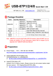
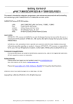
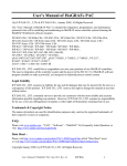
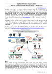
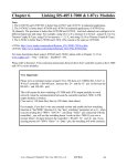
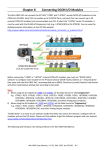
Application: Cost Effective Redundancy System by uPAC-7186EG or i-8437-80
Note:
1. W-8347 and W-8747 support better CPU redundancy solutions. Please refer to www.icpdas.com >
FAQ > Software > ISaGRAF > 041 and 062 . The CPU speed of Wincon is about 10 to 20 times
faster compared with the 40MHz i-8417/8817/8437/8837 and i-7188EG/XG ‘s CPU.
2. The uPAC-7186EG and i-8437-80 can setup a redundancy system. Their CPUs are 80MHz. The
CPU speed is about 2 to 4 times faster compared with the 40MHz i-7188EG/XG ‘s CPU.
1. Hot-Swap Redundancy System by uPAC-7186EG plus RU-87P4 / RU-87P8
uPAC-7186EG (Driver since it is released) supports Redundancy solution. The configuration is listed
as the following. It supports hot-swap I/O if using RS-485 expansion unit of RU-87P4 and RU-87P8
plus high-profile i-87K I/O cards . The Ebus are for exchanging data between the “Redundant Master”
& “Redundant Slave” . The controller status inputs in X-107 ’s D/I channel are to indicate the other
controller – “I am still alive” . Please wire Ch. 1 output of the redundant master ’s X-107 to Ch.1 input
of the redundant slave ’s X-107. And also wire Ch. 1 output of the redundant slave ’s X-107 to Ch.1
input of the redundant master ’s X-107.
uPAC-7186EG : Redundancy system
COM2: RS485
D2+ D2-
Limitation: Please do not connect more than 20 pcs. of i-7000
or i-87K I/O modules in the uPAC-7186EG redundancy system
RS485
uPAC-7186EG
+ slot 0: X-107
(Redundant Master)
Ebus
Ethernet
cross cable
uPAC-7186EG
+ slot 0: X-107
(Redundant Slave)
COM2: RS485
D2+ D2-
Controller
status input
in X-107
I-7000
I/O
Ru-87P4
Ru-87P8
I-87K4/5/8/9 +
I-87K I/O
Advantage of Ru-87P4 / 8 + High-profile i87K I/O cards:
1. I/O cards support Hot-swap.
2. Supports I/O auto-config at run time.
3. Supports I/O “plug and play” at run time.
http://www.icpdas.com/products/io_expansion_u
nit/ru-87p/Products-introduction_ru-87p.htm
Operations Principle:
1. When the system is powered up, the control of RS-485 I/O modules belong to “Redundant Master”.
2. If “Redundant Master” is damaged(or Power off), “Redundant Slave” takes the control of RS-485
I/O modules.
3. If “Redundant Master” is alive from damaged (or power up again), it takes the control of RS-485 I/O
modules again. The change over time of (2) and (3) is about 5 seconds.
4. Control data is exchanging via Ebus (if using a cross cable, no need any ethernet switch) .
5. All I/O should be RS-485 I/O except the status I/O in the slot 0: X-107
Jan.2008 , Copyright by ICP DAS
Demo program: new “demo_51a” and “demo_51b” released since Nov.10,2007
i-8000 CD-ROM: \napdos\isagraf\7188eg\demo\ or
ftp://ftp.icpdas.com/pub/cd/8000cd/napdos/isagraf/7188eg/demo/
User can use the “COM_MRTU” function to disable the uPAC-7186EG ‘s COM1 port if it is NOT
redundant active (then its COM1 will never answer any question to the PC / HMI / SCADA). And also
enable its COM1 by “COM_MRTU” function if it is redundancy active. Then at any time only the
redundancy active controller will reply to the PC / HMI / SCADA as below configuration. (Please
refer to demo_51a & demo_51b). Section 3 of this paper lists the steps to setup the i-7188EX-MTCP
(Modbus TCP/IP to Modbus RTU gateway). (Important: Please set these two uPAC-7186EG ‘s
Net-ID to the same No. for ex. , setting as No. 1. And the IP should be different but in the same
domain. For ex. , setting as 192.168.1.8 and 192.168.1.9. Mask should all set to 255.255.255.0)
Some important note in the demo program “demo_51a” and “demo_51b” :
1. If your application doesn’t setup any HMI or SCADA device to connect to this redundancy system,
you can delete the first Ladder rung which using the “COM_MRTU” function in the “M_B7000”
program in the “demo_51a” and in “S_B7000” program in the “demo_51b”. Then the COM1 port of
the uPAC-7186EG will be always Modbus RTU slave port. It will reply always if you send Modbus
request to it even it is not redundant active.
Jan.2008 , Copyright by ICP DAS
2. There are three useful variables which show “who is the current active controller” and the
“controller (or Ebus communication or DI / DO) status” . Your HMI and SCADA can request these
three values to know the current working status if assigning a proper Modbus network number to them.
They are listed as following.
Name
Type
Description
i_am
Integer
Master_Ok
Boolean
Slave_Ok
Boolean
1 : means I am Master controller
2 : means I am Slave controller
True : Master controller is working OK
Flase: Master controller is not working OK
(for ex, power OFF, Ebus cable broken, DI/DO broken)
True : Slave controller is working OK
Flase: Slave controller is not working OK
(for ex, power OFF, Ebus cable broken, DI/DO broken)
NetWork
number
Not assigned
yet
Not assigned
yet
Not assigned
yet
3. There are three programs should to be modified in “demo_51a” and “demo_51b” to fit your real
application.
(1) In the “M_B7000” and “S_B7000” programs:
search the “Add YOUR RS-485 I/O CONTROL of BUS7000 Here”
(2) In the “M_Contrl” and “S_Contrl” programs:
search the “Add YOUR CONTROLL data here”
(3) In the “M_Ebus” and “S_Ebus” programs:
search the “ADD YOUR EBUS CONTROL in the Following”
4. All the other programs below the “M_Ebus” and “S_Ebus” in the “demo_51a” and “demo_51b”
should be identical programs. Only the first 4 - “M_GET_P” , “M_B7000” , “M_Contrl” & “M_Ebus”
in the “demo_51a” are different as the first 4 - “S_GET_P” , “S_B7000” , “S_Contrl” & “S_Ebus” in
the “demo_51b” .
The order of the first 4 programs from
top to down should be “M_GET_ P” ,
“M_B7000” , “M_Contrl” , “M_Ebus” .
DO NOT place them with wrong order.
Jan.2008 , Copyright by ICP DAS
2. Hot-Swap Redundancy System by i-8437-80 plus RU-87P4 / RU-87P8
I-8437-80 / i-8837-80 (Driver rev.3.23 or later version) supports Redundant Bus7000b. The
configuration is listed as the following. It supports hot-swap I/O if using RS-485 expansion unit of
RU-87P4 and RU-87P8 . The Ebus are for exchanging data between the “Redundant Master” &
“Redundant Slave” . The controller status inputs in i-8054’s D/I channel are to indicate the other
controller – “I am still alive” . Please wire Ch. 1 ouput of the redundant master ’s i-8054 to Ch.1 input
of the redundant slave ’s i-8054. And also wire Ch. 1 ouput of the redundant slave ’s i-8054 to Ch.1
input of the redundant master ’s i-8054.
I-8437-80 : Redundancy system
COM3: RS485
Pin 1: D+ Pin 9: D-
Limitation: Please do not connect more than 20 pcs. of i-7000
or i-87K I/O modules in the i-8437-80 redundancy system
RS485
i-8437-80 / i-8837-80
+ slot 0: i-8054
(Redundant Master)
Ebus
Ethernet
cross cable
i-8437-80 / i-8837-80
+ slot 0: i-8054
(Redundant Slave)
COM3: RS485
Pin 1: D+ Pin 9: D-
Controller
status input
in i-8054
I-7000
I/O
Ru-87P4
Ru-87P8
I-87K4/5/8/9 +
I-87K I/O
Advantage of Ru-87P4 / 8 + High-profile i87K I/O cards:
1. I/O cards support Hot-swap.
2. Supports I/O auto-config at run time.
3. Supports I/O “plug and play” at run time.
http://www.icpdas.com/products/io_expansion_u
nit/ru-87p/Products-introduction_ru-87p.htm
Operations Principle:
1. When the system is powered up, the control of RS-485 I/O modules belong to “Redundant Master”.
2. If “Redundant Master” is damaged( or Power off), “Redundant Slave” takes the control of RS-485
I/O modules.
3. If “Redundant Master” is alive from damaged (or power up again), it takes the control of RS-485 I/O
modules again. The change over time of (2) and (3) is about 5 seconds.
4. Control data is exchanging via Ebus (if using a cross cable,no need any ethernet switch) .
5. All I/O should be RS-485 I/O except the status I/O in the slot 0: i-8054
Jan.2008 , Copyright by ICP DAS
Demo program: new “demo_48a” and “demo_48b” released since Nov.10,2007
i-8000 CD-ROM: \napdos\isagraf\8000\demo\ or
ftp://ftp.icpdas.com/pub/cd/8000cd/napdos/isagraf/8000/demo/
User can use the “COM_MRTU” function to disable the i-8437-80 ‘s COM1 port if it is NOT
redundant active (then its COM1 will never answer any question to the PC / HMI / SCADA). And also
enable its COM1 by “COM_MRTU” function if it is redundancy active. Then at any time only the
redundancy active controller will reply to the PC / HMI / SCADA as below configuration. (Please
refer to demo_49a & demo_49b). Section 3 of this paper lists the steps to setup the i-7188EX-MTCP
(Modbus TCP/IP to Modbus RTU gateway). (Important: Please set these two i-8437-80 ‘s Net-ID to
the same No. for ex. , setting as No. 1. And the IP should be different but in the same domain.
For ex. , setting as 192.168.1.8 and 192.168.1.9. Mask should all set to 255.255.255.0)
Some important note in the demo program “demo_49a” and “demo_49b” :
1. If your application doesn’t setup any HMI or SCADA device to connect to this redundancy system,
you can delete the first Ladder rung which using the “COM_MRTU” function in the “M_B7000”
program in the “demo_49a” and in “S_B7000” program in the “demo_49b”. Then the COM1 port of
the i-8437-80 will be always Modbus RTU slave port. It will reply always if you send Modbus request
to it even it is not redundant active.
Jan.2008 , Copyright by ICP DAS
2. There are three useful variables which show “who is the current active controller” and the
“controller (or Ebus communication or DI / DO) status” . Your HMI and SCADA can request these
three values to know the current working status if assigning a proper Modbus network number to them.
They are listed as following.
Name
Type
Description
i_am
Integer
Master_Ok
Boolean
Slave_Ok
Boolean
1 : means I am Master controller
2 : means I am Slave controller
True : Master controller is working OK
Flase: Master controller is not working OK
(for ex, power OFF, Ebus cable broken, DI/DO broken)
True : Slave controller is working OK
Flase: Slave controller is not working OK
(for ex, power OFF, Ebus cable broken, DI/DO broken)
NetWork
number
Not assigned
yet
Not assigned
yet
Not assigned
yet
3. There are three programs need to be modified in “demo_49a” and “demo_49b” to fit your real
application.
(1) In the “M_B7000” and “S_B7000” programs:
search the “Add YOUR RS-485 I/O CONTROL of BUS7000 Here”
(2) In the “M_Contrl” and “S_Contrl” programs:
search the “Add YOUR CONTROLL data here”
(3) In the “M_Ebus” and “S_Ebus” programs:
search the “ADD YOUR EBUS CONTROL in the Following”
4. All the other programs below the “M_Ebus” and “S_Ebus” in the “demo_49a” and “demo_49b”
should be identical programs. Only the first 4 - “M_GET_P” , “M_B7000” , “M_Contrl” & “M_Ebus”
in the “demo_49a” are different as the first 4 - “S_GET_P” , “S_B7000” , “S_Contrl” & “S_Ebus” in
the “demo_49b” .
The order of the first 4 programs from
top to down should be “M_GET_ P” ,
“M_B7000” , “M_Contrl” , “M_Ebus” .
DO NOT place them with wrong order.
Jan.2008 , Copyright by ICP DAS
3. Configure the i-7188EX-MTCP to link to the redundancy system
If you have installed i-7188EX-MTCP in this example, please set a fixed IP to it by the “7188xw.exe”
utility. (Power off 7188EX-MTCP, short its “INIT*” pin to “GND” , power it up, connecting one
RS232 cable from i-7188EX-MTCP ‘s COM1 to PC ‘s COM1, PC running “7188xw.exe”, key-in, for
ex, “ip=10.0.0.107” to set ip address and “mask=255.255.255.0” to set mask address)
After i-7188EX-MTCP ’s IP and Mask is well set. Please run “Modbus utility” to configure this i7188EX-MTCP to become a Modbus TCP/IP to Modbus RTU Gateway as below steps.
Please set its COM1 as “Debug” mode.
Jan.2008 , Copyright by ICP DAS
Then please set COM2 to “Modbus/RTU Gateway” , a proper timeout (250 ms), other parameters as
19200,8,None,1 . then Click on “Set”
In the “System Setting” area, please set this i-7188EX-MTCP ‘s Net-ID to a value not equal to 1, for
example, 100. And “Stations per COM Port as 1” , then click on “Set”.
If it display “Modbus ID (1 ~ 1) ==> COM2” , the configuration is well done.
Note: If i-7188EX-MTCP ‘s COM1 is not set as “Debug” mode in the former page, the setting will
become “Modbus ID (1 ~ 1) ==> COM1” . That is not correct, because here we want it send to i7188EX-MTCP ‘ s COM2:RS-485.
Then when this i-7188EX-MTCP receives Modbus TCP/IP protocol to request Net-ID: 1, it will send
this request to its COM2:RS-485 . And then if controller reply, it will reply back to the Ethernet port.
Jan.2008 , Copyright by ICP DAS