1
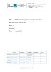
Product User Manual for “Cloud
Products” (CMa-PGE01 v3.2, CTPGE02 v2.2 & CTTH-PGE03
v2.2)
Code:
Issue:
File:
Page:
SAF/NWC/CDOP/MFL/SCI/PUM/01
3.2 Date: 15 February 2012
SAF-NWC-CDOP-MFL-SCI-PUM-01_v3.2
Product User Manual for “Cloud
Products” (CMa-PGE01 v3.2, CTPGE02 v2.2 & CTTH-PGE03 v2.2)
SAF/NWC/CDOP/MFL/SCI/PUM/01, Issue 3, Rev. 2
15 February 2012
Applicable to SAFNWC/MSG version 2012
Prepared by Météo-France / Centre de Météorologie Spatiale
1/32
Product User Manual for “Cloud
Products” (CMa-PGE01 v3.2, CTPGE02 v2.2 & CTTH-PGE03
v2.2)
Code:
Issue:
File:
Page:
SAF/NWC/CDOP/MFL/SCI/PUM/01
3.2 Date: 15 February 2012
SAF-NWC-CDOP-MFL-SCI-PUM-01_v3.2
2/32
REPORT SIGNATURE TABLE
Function
Prepared by
Reviewed by
Name
Marcel Derrien
MF/DP/CMS
Hervé Le Gléau
MF/DP/CMS
Signature
Date
15 February 2012
15 February 2012
Pilar Fernandez
Authorised by
SAFNWC Project
Manager
15 February 2012
Product User Manual for “Cloud
Products” (CMa-PGE01 v3.2, CTPGE02 v2.2 & CTTH-PGE03
v2.2)
Code:
Issue:
File:
Page:
SAF/NWC/CDOP/MFL/SCI/PUM/01
3.2 Date: 15 February 2012
SAF-NWC-CDOP-MFL-SCI-PUM-01_v3.2
3/32
DOCUMENT CHANGE RECORD
Version
1.4
Date
7 November 2007
2.0
3.0
3.1
3.2
23 August 2008
17 may 2010
24 march 2011
15 February 2012
Pages
CHANGE(S)
30
Initial version (content derived from “User
manual for PGE01-02-03 v1.3 (Cloud Products)
of the SAFNWC/MSG: scientific part”)
31
Content adapted to version v2.0
33
Content adapted to version v3.0
32
Content adapted to version v3.1
32
Content adapted to version v3.2
Product User Manual for “Cloud
Products” (CMa-PGE01 v3.2, CTPGE02 v2.2 & CTTH-PGE03
v2.2)
Code:
Issue:
File:
Page:
SAF/NWC/CDOP/MFL/SCI/PUM/01
3.2 Date: 15 February 2012
SAF-NWC-CDOP-MFL-SCI-PUM-01_v3.2
4/32
Table of contents
1.
INTRODUCTION ...................................................................................................................7
1.1
SCOPE OF THE DOCUMENT .......................................................................................................7
1.2
SCOPE OF OTHER DOCUMENTS.................................................................................................7
1.3
SOFTWARE VERSION IDENTIFICATION .....................................................................................7
1.4
IMPROVEMENT FROM PREVIOUS VERSION ................................................................................7
1.5
DEFINITIONS, ACRONYMS AND ABBREVIATIONS ....................................................................7
1.6
REFERENCES ...........................................................................................................................8
1.6.1
Applicable Documents...................................................................................................8
1.6.2
Reference Documents ....................................................................................................8
2.
CLOUD MASK (CMA) PRODUCT......................................................................................9
2.1
DESCRIPTION OF CLOUD MASK (CMA) PRODUCT.....................................................................9
2.1.1
Goal of Cloud Mask (CMa) product .............................................................................9
2.1.2
Outline of Cloud Mask (CMa) algorithm .....................................................................9
2.1.3
Description of Cloud Mask (CMa) output...................................................................11
2.2
IMPLEMENTATION OF CLOUD MASK (CMA) .........................................................................12
Manual preparation of Cloud Mask (CMa) model configuration file for each region ...............13
2.2.2
The Cloud Mask (CMa) preparation step (optional)...................................................13
2.2.3
The Cloud Mask (CMa) execution step .......................................................................13
2.3
INPUTS AND CONFIGURABLE PARAMETERS FOR CLOUD MASK (CMA)...................................14
2.3.1
List of inputs for Cloud Mask (CMa) ..........................................................................14
2.3.2
Configurable parameters for Cloud Mask (CMa).......................................................15
2.4
CLOUD MASK (CMA) VALIDATION .......................................................................................15
2.4.1
Summary of Cloud Mask (CMa) validation results .....................................................15
2.4.2
Typical known problems and recommendation for use ...............................................16
2.5
EXAMPLE OF CLOUD MASK (CMA) VISUALISATION .............................................................16
3.
CLOUD TYPE (CT) PRODUCT .........................................................................................18
3.1
DESCRIPTION OF CLOUD TYPE (CT) PRODUCT ......................................................................18
3.1.1
Goal of Cloud Type (CT) product ...............................................................................18
3.1.2
Outline of Cloud Type (CT) algorithm ........................................................................18
3.1.3
Description of Cloud Type (CT) output.......................................................................18
3.2
IMPLEMENTATION OF CLOUD TYPE (CT) ..............................................................................20
3.2.1
Manual preparation of Cloud Type (CT) model configuration file for each region ...20
3.2.2
The Cloud Type (CT) preparation step (optional).......................................................21
3.2.3
The Cloud Type (CT) execution step ...........................................................................21
3.3
INPUTS AND CONFIGURABLE PARAMETERS FOR CLOUD TYPE (CT) .......................................21
3.3.1
List of inputs for Cloud Type (CT) ..............................................................................21
3.3.2
Configurable parameters for Cloud Type (CT)...........................................................22
3.4
CLOUD TYPE (CT) VALIDATION ...........................................................................................23
3.4.1
Summary of Cloud Type (CT) validation results.........................................................23
3.4.2
Typical known problems and recommendation for use ...............................................23
3.5
EXAMPLE OF CLOUD TYPE (CT) VISUALISATION ..................................................................23
4.
CLOUD TOP TEMPERATURE AND HEIGHT (CTTH) PRODUCT...........................25
4.1
DESCRIPTION OF CLOUD TOP TEMPERATURE AND HEIGHT (CTTH) PRODUCT ......................25
4.1.1
Goal of Cloud Top Temperature and Height (CTTH) product ...................................25
4.1.2
Outline of Cloud Top Temperature and Height (CTTH) algorithm ............................25
4.1.3
Description of Cloud Top Temperature and Height (CTTH) output...........................26
4.2
IMPLEMENTATION OF CLOUD TOP TEMPERATURE AND HEIGHT (CTTH) ..............................28
Product User Manual for “Cloud
Products” (CMa-PGE01 v3.2, CTPGE02 v2.2 & CTTH-PGE03
v2.2)
Code:
Issue:
File:
Page:
SAF/NWC/CDOP/MFL/SCI/PUM/01
3.2 Date: 15 February 2012
SAF-NWC-CDOP-MFL-SCI-PUM-01_v3.2
5/32
4.2.1
Manual preparation of Cloud Top Temperature and Height (CTTH) model
configuration file for each region................................................................................................29
4.2.2
The Cloud Top Temperature and Height (CTTH) preparation step (optional)...........29
4.2.3
The Cloud Top Temperature and Height (CTTH) execution step ...............................29
4.3
INPUTS AND CONFIGURABLE PARAMETERS FOR CLOUD TOP TEMPERATURE AND HEIGHT
(CTTH)............................................................................................................................................29
4.3.1
List of inputs for Cloud Top Temperature and Height (CTTH) ..................................29
4.3.2
Configurable parameters for Cloud Top Temperature and Height (CTTH)...............31
4.4
CLOUD TOP TEMPERATURE AND HEIGHT (CTTH) VALIDATION ...........................................31
4.4.1
Summary of Cloud Top Temperature and Height (CTTH) validation results.............31
4.4.2
Typical known problems and recommendation for use ...............................................31
4.5
EXAMPLE OF CLOUD TOP TEMPERATURE AND HEIGHT (CTTH) VISUALISATION ...................32
Product User Manual for “Cloud
Products” (CMa-PGE01 v3.2, CTPGE02 v2.2 & CTTH-PGE03
v2.2)
Code:
Issue:
File:
Page:
SAF/NWC/CDOP/MFL/SCI/PUM/01
3.2 Date: 15 February 2012
SAF-NWC-CDOP-MFL-SCI-PUM-01_v3.2
6/32
List of Tables and Figures
Table 1: List of Applicable Documents.............................................................................................8
Table 2: List of Referenced Documents............................................................................................8
Table 3: Test sequence over land ....................................................................................................10
Table 4: Test sequence over sea ......................................................................................................10
Table 5: Summary of validation results of the current PGE01 version (POD stands for Percentage
Of Detection). .........................................................................................................................16
Table 6: Summary of validation results of the current PGE02 version.[AD. 5] .............................23
Table 7: Summary of validation results of the current PGE03 version (std stands for standard
deviation). ...............................................................................................................................31
Figure 1: Example of SEVIRI dust cloud flag superimposed on a 10.8μm infrared image: dust
cloud over North Africa on 14th July 2003 at 13h00 UTC. .....................................................17
Figure 2: Example of MODIS volcanic ash cloud superimposed on a 10.8μm infrared image: Etna
eruption on 22th July 2001 at 9h55 UTC. ...............................................................................17
Figure 3: Example of SEVIRI CT cloud type using the colour palette included in CT HDF files. 24
Figure 4 Example of SEVIRI CT cloud phase using the colour palette included in CT HDF files.
.................................................................................................................................................24
Figure 5: Example of SEVIRI CTTH cloud top pressure ...............................................................32
Product User Manual for “Cloud
Products” (CMa-PGE01 v3.2, CTPGE02 v2.2 & CTTH-PGE03
v2.2)
Code:
Issue:
File:
Page:
SAF/NWC/CDOP/MFL/SCI/PUM/01
3.2 Date: 15 February 2012
SAF-NWC-CDOP-MFL-SCI-PUM-01_v3.2
7/32
1. INTRODUCTION
The Eumetsat “Satellite Application Facilities” (SAF) are dedicated centres of excellence for
processing satellite data, and form an integral part of the distributed EUMETSAT Application
Ground Segment (http://www.eumetsat.int). This documentation is provided by the SAF on
Support to Nowcasting and Very Short Range Forecasting, SAFNWC. The main objective of
SAFNWC is to provide, further develop and maintain software packages to be used for
Nowcasting applications of operational meteorological satellite data by National Meteorological
Services. More information can be found at the SAFNWC webpage, http://nwcsaf.org . This
document is applicable to the SAFNWC processing package for Meteosat Second Generation
satellites, SAFNWC/MSG.
1.1 SCOPE OF THE DOCUMENT
This document is the Product User Manual for MSG cloud products PGE01 (CMa), PGE02 (CT)
and PGE03 (CTTH).
This document contains practical information on the characteristics of the above mentioned
products, on their applicability and limitations.
1.2 SCOPE OF OTHER DOCUMENTS
The algorithms used to extract the MSG Cloud Products PGE01 (CMa), PGE02 (CT) and PGE03
(CTTH) are detailed in the algorithm theoretical basis document for cloud products ( [AD. 4]).
The validation of the algorithms used to extract the MSG Cloud Products PGE01 (CMa), PGE02
(CT) and PGE03 (CTTH) is reported in the validation report for cloud products ([AD. 5]).
Instructions to install, configure and execute the SAFNWC/MSG software in order to extract the
MSG Cloud Products PGE01 (CMa), PGE02 (CT) and PGE03 (CTTH) are detailed in the
software user manual (AD. 3).
The interface control documents (AD. 1) (for the External and Internal Interfaces of the
SAFNWC/MSG) and (AD. 2) (MSG Output Product Format Definition) detail the input and
output data format for the SAFNWC/MSG software.
1.3 SOFTWARE VERSION IDENTIFICATION
This document describes the products obtained from the CMa-PGE01 V3.2, CT-PGE02 v2.2 and
CTTH-PGE03 v2.2 implemented in the release2012 of the SAFNWC/MSG software package.
1.4 IMPROVEMENT FROM PREVIOUS VERSION
CMa, CT and CTTH algorithms remain unchanged since previous version (v2011).
1.5 DEFINITIONS, ACRONYMS AND ABBREVIATIONS
CMa
CMS
CTTH
CT
ECMWF
Cloud Mask (also PGE01)
Centre de Meteorologie Spatiales (Météo-France, satellite reception centre
in Lannion)
Cloud Top Temperature and Height
Cloud Type
European Centre for Medium range Weather Forecast
Product User Manual for “Cloud
Products” (CMa-PGE01 v3.2, CTPGE02 v2.2 & CTTH-PGE03
v2.2)
EUMETSAT
FOV
HDF
HRIT
HRV
ICD
MSG
NWP
PGE
PUM
R0.6μm
RTMOM
RTTOV
SAF
SAF NWC
SAF OSI
SEVIRI
SW
T11μm
Code:
Issue:
File:
Page:
SAF/NWC/CDOP/MFL/SCI/PUM/01
3.2 Date: 15 February 2012
SAF-NWC-CDOP-MFL-SCI-PUM-01_v3.2
8/32
European Organisation for the Exploitation of Meteorological Satellites
Field Of View
Hierarchical data Format
High Rate Information Transmission
High Resolution Visible
Interface Control Document
Meteosat Second Generation
Numerical Weather Prediction
Product Generation Element
Product User Manual
0.6 visible reflectance
Radiative Transfer based on Matrix Operator Method
Rapid Transmissions for TOVs
Satellite Application Facility
SAF on support to NoWCasting and VSRF
Ocean and Sea Ice SAF
Spinning Enhanced Visible & Infrared Imager
Software
11 micrometer infrared brightness temperature
1.6 REFERENCES
1.6.1 Applicable Documents
Reference
[AD. 1]
[AD. 2]
[AD. 3]
[AD. 4]
[AD. 5]
Title
Interface Control Document for the External
and Internal Interfaces of the SAFNWC/MSG
SAFNWC/MSG Output Products Format
Definition
Software User Manual for the SAFNWC/MSG
application
Algorithm Theoretical Basis Document for
“Cloud Products” (CMa-PGE01 v3.2, CTPGE02 v2.2 & CTTH-PGE03 v2.2)
Validation Report for “Cloud Products” (CMaPGE01 v3.2, CT-PGE02 v2.2 & CTTH-PGE03
v2.2)
Code
SAF/NWC/IOP/INM/SW/ICD/1
Vers
2.0
Date
SAF/NWC/IOP/INM/SW/ICD/3
2.0
SAF/NWC/IOP/INM/SW/SUM/2
2.0
SAF/NWC/CDOP/MFL/SCI/ATB
D/01
3.2
15/02/12
SAF/NWC/CDOP/MFL/SCI/VR/06
1.0
15/02/12
Vers
Date
Table 1: List of Applicable Documents
1.6.2 Reference Documents
Reference
[RD.1]
[RD.2]
Title
Code
Table 2: List of Referenced Documents
Product User Manual for “Cloud
Products” (CMa-PGE01 v3.2, CTPGE02 v2.2 & CTTH-PGE03
v2.2)
Code:
Issue:
File:
Page:
SAF/NWC/CDOP/MFL/SCI/PUM/01
3.2 Date: 15 February 2012
SAF-NWC-CDOP-MFL-SCI-PUM-01_v3.2
9/32
2. CLOUD MASK (CMA) PRODUCT
2.1 DESCRIPTION OF CLOUD MASK (CMA) PRODUCT
2.1.1 Goal of Cloud Mask (CMa) product
The cloud mask (CMa), developed within the SAF NWC context, aims to support nowcasting
applications, and additionally the remote-sensing of continental and oceanic surfaces. The CMa
allows identifying cloud free areas where other products (total or layer precipitable water, land or
sea surface temperatures, snow/ice cover delineation) may be computed. It also allows identifying
cloudy areas where other products (cloud types and cloud top temperature/height) may be derived.
The central aim of the CMa is therefore to delineate all cloud-free pixels in a satellite scene with a
high confidence. In addition, the product provides information on the presence of snow/sea ice,
dust clouds and volcanic plumes.
2.1.2 Outline of Cloud Mask (CMa) algorithm
The algorithm is based on multispectral threshold technique applied to each pixel of the image. A
first process allows the identification of cloudy pixels. It consists in a first set of multispectral
threshold tests (summed up below) which is complemented by an analysis of the temporal
variation (on a short period of time: 15 minutes) of some spectral combinations of channels (to
detect rapidly moving clouds), a specific treatment combining temporal coherency analysis and
region growing technique (to improve the detection of low clouds) and a temporal analysis of the
HRV channel (to detect sub-pixel cumulus clouds).
The first series of tests allows the identification of pixels contaminated by clouds or snow/ice; this
process is stopped if one test is really successful (i.e., if the threshold is not too close to the
measured value). The characteristics of this set of tests are summed up below:
•
The tests, applied to land or sea pixels, depend on the solar illumination and on the
viewing angles and are presented in Table 3 and Table 4.
•
Most thresholds are determined from satellite-dependent look-up tables (available in
coefficients’ files) using as input the viewing geometry (sun and satellite viewing angles),
NWP forecast fields (surface temperature and total atmospheric water vapour content) and
ancillary data (elevation and climatological data). The thresholds are computed at a spatial
resolution (called “segment size”) defined by the user as a number of SEVIRI infra-red
pixels. Some thresholds are empirical constant or satellite-dependent values (available in
coefficients’ files).
•
The quality of the cloud detection process is assessed.
•
A spatial filtering is applied, allowing to reclassify pixels having a class type different
from their neighbours and to reduce known defaults as cloud false alarms in coastal area
and in edges of snowy areas.
•
A test is applied to cloud contaminated pixels to check whether the cloud cover is opaque
and completely fills the FOV.
This first series of tests allows to determine the cloud cover category of each pixel (cloud-free,
cloud contaminated, cloud filled, snow/ice contaminated or undefined/non processed) and
compute a quality flag on the processing itself. Moreover, the tests that have allowed the cloud
detection (more that one test are possible, if some tests were not really successful) are stored.
Product User Manual for “Cloud
Products” (CMa-PGE01 v3.2, CTPGE02 v2.2 & CTTH-PGE03
Code:
Issue:
File:
Page:
v2.2)
SAF/NWC/CDOP/MFL/SCI/PUM/01
3.2 Date: 15 February 2012
SAF-NWC-CDOP-MFL-SCI-PUM-01_v3.2
10/32
A second process, allowing the identification of dust clouds and volcanic ash clouds, is applied to
all pixels (even already classified as cloud-free or contaminated by clouds). The result is stored in
the dust cloud and volcanic ash cloud flags.
Details on the tests are given in the algorithm theoretical basis document for cloud products
([AD. 4]).
Daytime
Twilight
Nighttime
Snow detection
Snow detection
T10.8μm
T10.8μm
T10.8μm
T10.8μm-T12.0μm
R0.6μm
R0.6μm
T8.7μm-T10.8μm
T10.8μm-T12.0μm
T10.8μm-T12.0μm
T10.8μm-T8.7μm
T8.7μm-T10.8μm
T8.7μm-T10.8μm
T10.8μm-T3.9μm
T10.8μm-T3.9μm
T10.8μm-T8.7μm
T3.9μm-T10.8μm
T3.9μm-T10.8μm
T10.8μm-T3.9μm
Local Spatial Texture
Local Spatial Texture
T3.9μm-T10.8μm
T8.7μm-T3.9μm
Local Spatial Texture
T8.7μm-T3.9μm
Table 3: Test sequence over land
Daytime
Sunglint
Twilight
Nighttime
Ice detection
Ice detection
Ice detection
SST
SST
SST
SST
T10.8μm-T12.0μm
R0.8μm (R0.6μm)
T10.8μm-T12.0μm
R0.8μm (R0.6μm)
T8.7μm-T10.8μm
R1.6μm
T8.7μm-T10.8μm
R1.6μm
T10.8μm-T3.9μm
T10.8μm-T12.0μm
Local Spatial Texture
T10.8μm-T12.0μm
T12.0μm-T3.9μm
T8.7μm-T10.8μm
R0.8μm (R0.6μm)
T8.7μm-T10.8μm
T3.9μm-T10.8μm
T10.8μm-T3.9μm
T10.8μm-T3.9μm
T10.8μm-T3.9μm
Local Spatial Texture
T3.9μm-T10.8μm
Low Clouds in Sunglint
T12.0μm-T3.9μm
Local Spatial Texture
T3.9μm-T10.8μm
Local Spatial Texture
Table 4: Test sequence over sea
[T3.9μm, T8.7μm , T10.8μm and T12.0μm stand for brightness temperatures at 3.9, 8.7, 10.8 and 12.0
micrometer ; R0.6μm,R0.8μm and R1.6μm stand for VIS/NIR bi-directional top of atmosphere reflectances at
0.6, 0.8 and 1.6 micrometer normalised for solar illumination ; SST is the split-window (used for SST
calculation) computed from T10.8μm and T12.0μm measurements. Low Clouds in Sunglint is a specific module
for low clouds identification in sunglint areas.]
Product User Manual for “Cloud
Products” (CMa-PGE01 v3.2, CTPGE02 v2.2 & CTTH-PGE03
v2.2)
Code:
Issue:
File:
Page:
SAF/NWC/CDOP/MFL/SCI/PUM/01
3.2 Date: 15 February 2012
SAF-NWC-CDOP-MFL-SCI-PUM-01_v3.2
11/32
2.1.3 Description of Cloud Mask (CMa) output
The description of CMa output (in HDF format) is detailed in the output products format
definition document (AD. 2). This section summarizes the CMa output fields (a colour palette is
also included in the HDF CMa output file for each field, see 2.5).
•
0
1
2
3
4
5
•
The main product output consists in the following six categories coded on 3 bits
Non-processed
cloud-free
containing no data or corrupted data
no contamination by snow/ice covered surface,
no contamination by clouds ;
but contamination by thin dust/volcanic clouds not checked
Cloud contaminated partly cloudy or semitransparent. May also include dust clouds
or volcanic plumes.
Cloud filled
opaque clouds completely filling the FOV. May also include
thick dust clouds or volcanic plumes.
Snow/Ice contaminated
Undefined
has been processed but not classified due to known separability
problems
16 bits to describe which test was successful
For each cloudy pixel, the bits corresponding to the successful tests are activated. More than one
bit may be activated, if tests were not really successful (measurement too close to thresholds)).
0
T10.8μm or SST
1
R0.6μm (land) or R0.8μm (sea)
2
Sunglint test using 3.9μm
3
Local Spatial Texture
4
T10.8μm - T12.0μm
5
T10.8μm - T3.9μm or T12.0μm - T3.9μm
6
T3.9μm - T10.8μm
7
Spatial smoothing (reclassify isolated cloud-free pixels)
8
T8.7μm - T3.9μm
9
R1.6μm (sea)
10
T8.7μm –T10.8μm or T10.8μm –T8.7μm
11
Snow using R1.6μm or T3.9μm
12
HRV-based test
13
Stationary cloud in twilight
14
Spatial expansion of stationary cloud in twilight
15
Temporal-differencing
•
11 bits for quality
3 bits to define illumination and viewing conditions:
0
Undefined (space)
1
Night
2
Twilight
3
Day
4
Sunglint
2 bits to describe NWP input data
0
Undefined (space)
1
All NWP parameters available (no low level inversion)
2
All NWP parameters available (low level inversion)
3
At least one NWP parameter missing
Product User Manual for “Cloud
Products” (CMa-PGE01 v3.2, CTPGE02 v2.2 & CTTH-PGE03
v2.2)
Code:
Issue:
File:
Page:
SAF/NWC/CDOP/MFL/SCI/PUM/01
3.2 Date: 15 February 2012
SAF-NWC-CDOP-MFL-SCI-PUM-01_v3.2
12/32
2 bits to describe SEVIRI input data
0
Undefined (space)
1
All useful SEVIRI channels available ;
2
At least one useful SEVIRI channel missing
3
A least one mandatory SEVIRI channel missing
2 bits to describe the quality of the processing itself:
0
Non processed (containing no data or corrupted data)
1
Good quality (high confidence)
2
Poor quality (low confidence)
3
Reclassified after spatial smoothing (very low confidence)
1 bit for temporal processing indicator (significant for cloud-free pixels)
0
Not performed
1
Performed
1 bit for HRV processing indicator (significant for cloud-free pixels)
0
Not performed
1
Performed
•
0
1
2
3
•
0
1
2
3
2 bits for dust detection
Non processed (containing no data or corrupted data)
dust
non dust
undefined (due to known separability problems)
2 bits for volcanic plume detection
Non processed (containing no data or corrupted data)
volcanic plume
non volcanic plume
undefined (due to known separability problems)
2.2 IMPLEMENTATION OF CLOUD MASK (CMA)
CMa is extracted by PGE01 of the SAFNWC/MSG software package. Detailed information on
how to run this software package is available in the software user manual (AD. 3).
The software architecture of PGE01 has been strongly modified in version v2010 (to make the life
easier for the user). It is now very similar to the other PGEs.
When a new region is defined the user has now to manually prepare the CMa model configuration
files for this new region using a default CMa model configuration file provided in the
SAFNWC/MSG software package.
There is an option for the user to monitor the so-called CMa preparation step before SEVIRI
images are available (to speed up the process). By default, this preparation step is performed
during the CMa execution step.
The CMa execution step (which includes the CMa preparation step in case it has not been
launched before) is automatically launched by the Task Manager (if real-time environment is
selected).
Product User Manual for “Cloud
Products” (CMa-PGE01 v3.2, CTPGE02 v2.2 & CTTH-PGE03
v2.2)
Code:
Issue:
File:
Page:
SAF/NWC/CDOP/MFL/SCI/PUM/01
3.2 Date: 15 February 2012
SAF-NWC-CDOP-MFL-SCI-PUM-01_v3.2
13/32
2.2.1 Manual preparation of Cloud Mask (CMa) model configuration file for each
region
When a new region is defined and added in system and run configuration files, the user must
manually prepares the CMa model configuration files by adapting the CMa default model
configuration file available in the SAFNWC software package. Three parameters are configurable
in the default CMa model configuration file:
•
CMA_SZSEG (default value: 4): the size of the segment for CMa. The new segment size
must also be updated in the lines NWP_PARAMxx [Segments are square boxes in the
satellite projection, whose size is expressed as the number of IR pixels of one edge of the square box.
The size of the processed regions must be a multiple of the segment size. All the solar and satellite
angles, the NWP model forecast values, the atlas values and the thresholds will be derived over all the
processed regions at the horizontal resolution of the segment. Note also that the land/sea atlas will be
available at the full IR resolution, allowing the identification of the surface type (land or sea) of all IR
pixels, whatever the segment size. The quality is not very much dependent of the segment size (if lower
than 4). A segment size of 4 allows the preparation step to be 9 times faster than if a segment size of 1
was used]
•
TEMPORAL_USE (default value: TRUE): a flag defining if the temporal analysis should
be done. [TEMPORAL_USE flag is checked at the execution step. PGE01 applies the temporal
analysis if its value is TRUE. This flag has been made configurable to allow users being blocked by
hardware resources to still run the PGE01 by assigning it to FALSE in the configuration file.]
•
HRV_NEED (default value: TRUE): a flag indicating whether the HRV analysis should
be done. [HRV_NEED flag is checked at the execution step. PGE01 applies the HRV analysis if its
value is TRUE. This flag has been made configurable to allow users being blocked by hardware
resources to still run the PGE01 by assigning it to FALSE in the configuration file.] When required and
when the 2 HRV images required by the algorihm are not available the PGE01 is processed without this
enhancement. For regions being partially covered by HRV measurements, only the SEVIRI pixels
having HRV benefit from enhancement.
Moreover as the content of NWP_CONF_FILE is dependent on the local installation, the user
must make the NWP_PARAMXX consistent with the local NWP_CONF_FILE when the
standard one is not used (for details see section dedicated to NWP data files in
SAF/NWC/CDOP/INM/SW/SUM/2 [AD. 3]) .
2.2.2 The Cloud Mask (CMa) preparation step (optional)
By default, this CMa preparation step is performed during the CMa execution step (see 2.2.3).
But to speed up the CMa processing, this preparation step can performed by the command
mfcms_next_pge01 which can be launched in advance of satellite data reception according to a
pre-defined time scheduling to be manually set by the user.
This preparation step includes the computation on the region at the segment spatial resolution of:
• the solar & satellite angles,
• the monthly climatological & atlas maps,
• the thresholds for the CMa algorithm
2.2.3 The Cloud Mask (CMa) execution step
The CMa execution step (which by default includes the CMa preparation step see 2.2.2) is the
real-time processing of the SEVIRI images itself over the region. This process consists in the
launch of the command: PGE01 by the Task manager. The cloud masking is then performed,
using the thresholds prepared during the preparation step.
Product User Manual for “Cloud
Products” (CMa-PGE01 v3.2, CTPGE02 v2.2 & CTTH-PGE03
Code:
Issue:
File:
Page:
v2.2)
SAF/NWC/CDOP/MFL/SCI/PUM/01
3.2 Date: 15 February 2012
SAF-NWC-CDOP-MFL-SCI-PUM-01_v3.2
14/32
2.3 INPUTS AND CONFIGURABLE PARAMETERS FOR CLOUD MASK (CMA)
2.3.1 List of inputs for Cloud Mask (CMa)
The input data to the CMa algorithm are described in this section. Mandatory inputs are flagged,
whereas the impact of missing non-mandatory data on the processing are indicated.
•
Satellite imagery:
The following SEVIRI bi-directional reflectances or brightness temperatures of the scene to be
analysed are needed at full IR spatial resolution (at HRV spatial resolution for HRV):
HRV
R0.6μm
R0.8μm
R1.6μm
T3.9μm
T7.3μm
T8.7μm
T10.8μm
T12.0μm
T13.4μm
Optional
Mandatory
Optional
Optional
Mandatory
Optional
Optional
Mandatory
Mandatory
Optional
The CMa software checks the availability of SEVIRI channels for each pixel. If non mandatory
channels are missing for one pixel, the tests using these channels are not applied, or applied
differently (for example, snow detection uses either R1.6μm or T3.9μm; visible channel test over
the ocean uses either R0.8μm or R0.6μm) and a result is available for this pixel. No results are
provided for pixels where at least one mandatory channel is missing.
The following SEVIRI bi-directional reflectances or brightness temperatures or Cma or CT of the
scene analysed one hour sooner are optionally needed to improve the cloud detection in day-night
transition. If one of them misses this improvement is not performed.
R0.6μm1h
Optional
T8.7μm1h
Optional
T10.8μm1h T12.0μm1h
Optional
Optional
CMa1h
Optional
CT1h
Optional
The following SEVIRI brightness temperatures or Cma or CT of the scene analysed 15 minutes
sooner are optionally needed to improve the cloud detection of fast moving clouds. If one of them
misses this improvement is not performed.
T8.7μm15mn
Optional
T10.8μm15mn
Optional
T12.0μm15mn
Optional
CMa15mn
Optional
CT15mn
Optional
The HRV bi-directional reflectance of the scene analysed 15 minutes sooner are optionally needed
to improve the sub-pixel cumulus cloud detection. If not available this improvement is not
performed.
HRV15mn
Optional
The SEVIRI channels are input by the user in HRIT format, and extracted on the processed region
by SAFNWC software package.
•
Sun and satellite angles associated to SEVIRI imagery
This information is mandatory. It is computed by the CMa software itself, using the definition of
the region and the satellite characteristics.
•
NWP parameters:
The forecast fields of the following parameters, remapped onto satellite images, are used as input :
o surface temperatures (required to get good quality results over land ; but not
mandatory)
o air temperature at 950hPa (alternatively 925hPa). Used to check low level inversion.
o total water vapour content of the atmosphere,
o altitude of the NWP model grid (alternatively surface geopotential on the NWP model
grid). Required if NWP fields are used as input.
Product User Manual for “Cloud
Products” (CMa-PGE01 v3.2, CTPGE02 v2.2 & CTTH-PGE03
v2.2)
Code:
Issue:
File:
Page:
SAF/NWC/CDOP/MFL/SCI/PUM/01
3.2 Date: 15 February 2012
SAF-NWC-CDOP-MFL-SCI-PUM-01_v3.2
15/32
These remapped fields are elaborated by the SAFNWC software package from the NWP fields
input by the user in GRIB format.
The NWP fields are not mandatory: the CMa software replaces missing NWP surface
temperatures or total water vapour content of the atmosphere by climatological values extracted
from ancillary dataset, but the quality of CMa is then lower.
•
Ancillary data sets:
The following ancillary data, remapped onto satellite images, are mandatory :
o Land/sea atlas
o Land/sea/coast atlas
o Elevation atlas
o Monthly minimum SST climatology
o Monthly mean 0.6μm atmospheric-corrected reflectance climatology (land)
o Monthly mean large band visible surface reflectance climatology (land, for HRV
processing)
o Monthly integrated atmospheric water vapour content climatology
o Monthly climatology of mean air temperature at 1000 hPa
These ancillary data are available in the SAFNWC software package on MSG full disk in the
default satellite projection at full IR resolution; They are extracted on the processed region by the
CMa software itself.
Coefficients’s file (also called threshold tables), containing satellite-dependent values and look-up
tables for IR thresholds and for solar channels’ thresholds, are available in the SAFNWC software
package, and are needed by the CMa software.
2.3.2 Configurable parameters for Cloud Mask (CMa)
Three configurables parameters are available in the default CMa model configuration file:
•
CMA_SZSEG: The size of the segment is configurable (see its definition in 2.2.1). Its
default value is 4. Information on how to change the size of the segment can be found in
the software user manual (AD. 3) and in section 2.2.1.
•
TEMPORAL_USE: The flag defining if temporal information is to be used (to allow a
better detection of fast moving clouds and low clouds in twilight conditions) is
configurable (see its definition in 2.2.1). Its default value is TRUE. Information on how to
change this value can be found in the software user manual (AD. 3) and in section 2.2.1.
•
HRVNEED: The flag indicating if HRV data have to be used (to allow enhanced sub-pixel
cumulus detection) is configurable (see its definition in 2.2.1). Its default value is TRUE.
Information on how to change this value can be found in the software user manual (AD.
3) and in section 2.2.1.
2.4 CLOUD MASK (CMA) VALIDATION
2.4.1 Summary of Cloud Mask (CMa) validation results
Table 5 summarises the validation results of the current version. More details can be obtained
from the validation report for cloud products ([AD. 5]).
PGE01 flags
Validated accuracy
PGE01 cloud detection
Product User Manual for “Cloud
Products” (CMa-PGE01 v3.2, CTPGE02 v2.2 & CTTH-PGE03
v2.2)
validated over European areas using SYNOP
observations
PGE01 dust flag
validated over sea and Africa for solar
elevation larger than 20 degrees using
interactive targets
Code:
Issue:
File:
Page:
SAF/NWC/CDOP/MFL/SCI/PUM/01
3.2 Date: 15 February 2012
SAF-NWC-CDOP-MFL-SCI-PUM-01_v3.2
16/32
POD:96.5%
POD:
55.5% over sea
58.5% over land
Table 5: Summary of validation results of the current PGE01 version (POD stands for Percentage
Of Detection).
2.4.2 Typical known problems and recommendation for use
The following problems may be encountered:
•
Low clouds may be not detected in case low solar elevation, over both sea and land.
•
It may happen that large areas of low clouds are not detected in night-time conditions over
land. This can be the case in “warm sectors”, but also in areas viewed with high satellite
zenith angles or if the low clouds are surmounted by very thin cirrus.
•
Snowy grounds are not detected at night-time and therefore may confused either with low
clouds or cloud free surface. This drawback has been reduced with v3.1 in release2011.
•
False detection of volcanic ash clouds happens especially in daytime conditions (over low
clouds and desertic surfaces), but also in night-time (over cold clouds). The volcanic ash
clouds detection is not performed in case low solar elevation.
•
Over land, dust cloud detection is performed only at daytime. Over land, dust clouds are
not well detected when the sun is low or if they are too thin. Over sea, some dust areas
may not be detected (especially the thinnest parts). Moreover, some wrong detection may
be observed in oceanic regions, especially at nighttime near Namibia coast and
occasionally over the South Atlantic (at latitude larger than 50 degrees).
The CMa product may be used to identify cloud-free surfaces for oceanic or continental surface
parameters retrieval. Nevertheless, as some clouds remains undetected and to account for artefacts
such as shadows or aerosols, the user should apply a post-processing which could include:
•
the spreading of the cloud mask that should allow to detect cloud edges and mask shadows
or moist areas near cloud edges
•
the use of the cloud mask quality flag not to compute surface parameters in bad quality
cloud free areas
•
the implementation of an additional filtering based on the temporal variation around the
current slot
2.5 EXAMPLE OF CLOUD MASK (CMA) VISUALISATION
It is important to note that the CMa product is not just images, but numerical data. At first hand,
the CMa is rather thought to be used digitally (together with the appended flags (quality, dust
detection, volcanic ash detection)) as input to mesoscale analysis models, objective Nowcasting
schemes, but also during the extraction of other SAFNWC products (CT for example).
Colour palettes are included in CMa HDF files, allowing an easy visualisation of CMa main
categories, dust and volcanic ash clouds flags.
No example of CMa main categories’s visualisation are given, as it is thought that the user will be
more interested to visualize the CT product which can be seen as a refinement.
Product User Manual for “Cloud
Products” (CMa-PGE01 v3.2, CTPGE02 v2.2 & CTTH-PGE03
v2.2)
Code:
Issue:
File:
Page:
SAF/NWC/CDOP/MFL/SCI/PUM/01
3.2 Date: 15 February 2012
SAF-NWC-CDOP-MFL-SCI-PUM-01_v3.2
17/32
Example of visualisation of the dust cloud and the volcanic ash cloud flags superimposed on
infrared images are given in Figure 1 and Figure 2 , using SEVIRI and MODIS imagery.
Figure 1: Example of SEVIRI dust cloud flag superimposed on a 10.8μm infrared image: dust
cloud over North Africa on 14th July 2003 at 13h00 UTC.
Figure 2: Example of MODIS volcanic ash cloud superimposed on a 10.8μm infrared image: Etna
eruption on 22th July 2001 at 9h55 UTC.
Product User Manual for “Cloud
Products” (CMa-PGE01 v3.2, CTPGE02 v2.2 & CTTH-PGE03
v2.2)
Code:
Issue:
File:
Page:
SAF/NWC/CDOP/MFL/SCI/PUM/01
3.2 Date: 15 February 2012
SAF-NWC-CDOP-MFL-SCI-PUM-01_v3.2
18/32
3. CLOUD TYPE (CT) PRODUCT
3.1 DESCRIPTION OF CLOUD TYPE (CT) PRODUCT
3.1.1 Goal of Cloud Type (CT) product
The cloud type (CT), developed within the SAF NWC context, mainly aims to support nowcasting
applications. The main objective of this product is to provide a detailed cloud analysis. It may be
used as input to an objective meso-scale analysis (which in turn may feed a simple nowcasting
scheme), as an intermediate product input to other products, or as a final image product for
display at a forecaster’s desk. The CT product is essential for the generation of the cloud top
temperature and height product and for the identification of precipitation clouds. Finally, it is also
essential for the computation of radiative fluxes over sea or land, which are SAF Ocean & Sea Ice
products.
The CT product therefore contains information on the major cloud classes : fractional clouds,
semitransparent clouds, high, medium and low clouds (including fog) for all the pixels identified
as cloudy in a scene. A second priority is the distinction between convective and stratiform
clouds (implementation not planned before 2012), and the identification of clouds for which the
top mainly consists of water droplets.
3.1.2 Outline of Cloud Type (CT) algorithm
The CT algorithm is a threshold algorithm applied at the pixel scale, based on the use of CMa and
spectral & textural features computed from the multispectral satellite images and compared with a
set of thresholds.
The set of thresholds to be applied depends mainly on the illumination conditions, whereas the
values of the thresholds themselves may depend on the illumination, the viewing geometry, the
geographical location and NWP data describing the water vapour content and a coarse vertical
structure of the atmosphere.
Opaque clouds are first separated from semi-transparent and from fractional (sub-pixel) clouds
using brightness temperature differences (T10.8μm-T12.0μm, T8.7μm-T10.8μm or T3.9μmT10.8μm) and R0.6μm (at daytime). Opaque clouds are then separated in very low, low, midlevel, high or very high clouds using their T10.8mm brightness temperatures which are compared
to NWP forecast air temperatures at various pressure levels. Details are available in the algorithm
theoretical basis document for cloud products ([AD. 4]).
A separate processing is applied to compute the cloud phase flag, based on the use of CT cloud
type, T8.7μm,T10.8μm (all illumination), R0.6μm and R1.6μm (at daytime).
3.1.3 Description of Cloud Type (CT) output
The description of CT output (in HDF format) is detailed in the output products format definition
document (AD. 2). This section summarizes the CT output fields (a colour palette is also included
in the HDF CT output file for each field, see 3.5).
•
0
1
The main product output consists in the following twenty-one categories coded on 5
bits
non-processed containing no data or corrupted data
cloud free land
no contamination by snow/ice covered surface,
Product User Manual for “Cloud
Products” (CMa-PGE01 v3.2, CTPGE02 v2.2 & CTTH-PGE03
v2.2)
Code:
Issue:
File:
Page:
SAF/NWC/CDOP/MFL/SCI/PUM/01
3.2 Date: 15 February 2012
SAF-NWC-CDOP-MFL-SCI-PUM-01_v3.2
19/32
no contamination by clouds ;
but contamination by thin dust/volcanic clouds not checked
cloud free sea
no contamination by snow/ice covered surface,
no contamination by clouds ;
but contamination by thin dust/volcanic clouds not checked
land contaminated by snow
sea contaminated by snow/ice
very low and cumuliform clouds
very low and stratiform clouds
low and cumuliform clouds
low and stratiform clouds
medium and cumuliform clouds
medium and stratiform clouds
high opaque and cumuliform clouds
high opaque and stratiform clouds
very high opaque and cumuliform clouds
very high opaque and stratiform clouds
high semitransparent thin clouds
high semitransparent meanly thick clouds
high semitransparent thick clouds
high semitransparent above low or medium clouds
fractional clouds (sub-pixel water clouds)
undefined (undefined by CMa)
2
3
4
5
6
7
8
9
10
11
12
13
14
15
16
17
18
19
20
In the current version of CT, the separation between cumuliform and stratiform is not performed:
low, medium or high clouds will be classified as stratiform, and a specific bit indicating whether
the separation between stratiform and cumuliform clouds has been attempted, will be set to zero
(see below quality flag).
•
10 bits for quality
3 bits to define illumination and viewing conditions:
0
Undefined (space)
1
Night
2
Twilight
3
Day
4
Sunglint
2 bits to describe NWP input data
0
Undefined (space)
1
All NWP parameters available (no low level inversion)
2
All NWP parameters available (low level inversion)
3
At least one NWP parameter missing
2 bits to describe SEVIRI input data
0
Undefined (space)
1
All useful SEVIRI channels available ;
2
At least one useful SEVIRI channel missing
3
At least one mandatory SEVIRI channel missing
2 bits to describe the quality of the processing itself:
0
Non processed (containing no data or corrupted data)
1
Good quality (high confidence)
2
Poor quality (low confidence)
3
Reclassified after spatial smoothing (very low confidence)
1 bit
set to 1 to indicate that the separation between cumuliform and stratiform clouds has
Product User Manual for “Cloud
Products” (CMa-PGE01 v3.2, CTPGE02 v2.2 & CTTH-PGE03
v2.2)
Code:
Issue:
File:
Page:
SAF/NWC/CDOP/MFL/SCI/PUM/01
3.2 Date: 15 February 2012
SAF-NWC-CDOP-MFL-SCI-PUM-01_v3.2
20/32
been performed.
In the current version of CT, the separation between cumuliform and stratiform is not performed:
this bit will be set to zero and the low, medium or high clouds will be classified as stratiform.
•
2 bits for cloud phase
0
1
2
Non processed (containing no data or corrupted data) or no cloud
water cloud
ice cloud
3
undefined (due to known separability problems)
3.2 IMPLEMENTATION OF CLOUD TYPE (CT)
CT is extracted by PGE02 of the SAFNWC/MSG software package. Detailed information on how
to run this software package is available in the software user manual (AD. 3).
The software architecture of PGE02 has been strongly modified in version v2010 (to make the life
easier for the user). It is now very similar to the other PGEs.
When a new region is defined the user has now to manually prepare the CT model configuration
files for this new region using a default CT model configuration file provided in the
SAFNWC/MSG software package.
There is an option for the user to monitor the so-called CT preparation step before SEVIRI images
are available (to speed up the process). By default, this preparation step is performed during the
CT execution step.
The CT execution step (which includes the CT preparation step in case it has not been launched
before) is automatically launched by the Task Manager (if real-time environment is selected).
3.2.1 Manual preparation of Cloud Type (CT) model configuration file for each
region
When a new region is defined and added in system and run configuration files, the user must
manually prepares the CT model configuration files by adapting the default CT model
configuration file available in the SAFNWC software package.
Three parameters are configurable in the default CT model configuration file:
•
CT_SZSEG (default value: 4): the size of the segment. This default value may be
manually changed, but must be the same as for CMa (CMA_SZSEG)). The new segment
size must also updated in the lines NWP_PARAMxx [Segments are square boxes in the
satellite projection, whose size is expressed as the number of IR pixels of one edge of the square box.
The size of the processed regions must be a multiple of the segment size. All the solar and satellite
angles, the NWP model forecast values, the atlas values and the thresholds will be derived over all the
processed regions at the horizontal resolution of the segment. Note also that the land/sea atlas will be
available at the full IR resolution, allowing the identification of the surface type (land or sea) of all IR
pixels, whatever the segment size. The quality is not very much dependent on the segment size (if lower
than 4). A segment size of 4 allows the preparation step to be 9 times faster than if a segment size of 1
was used]
•
PHASE_COMPUTATION (default value: TRUE): a flag defining if the cloud phase flag
should be computed.[ PHASE_COMPUTATION flag is checked at the execution step. It should be
assigned to TRUE or FALSE. PGE02 computes the cloud phase flag if its value is TRUE. This flag has
been made configurable to allow users being blocked by hardware resources to still run the PGE02 by
assigning it to FALSE in the configuration file.]
Product User Manual for “Cloud
Products” (CMa-PGE01 v3.2, CTPGE02 v2.2 & CTTH-PGE03
v2.2)
•
Code:
Issue:
File:
Page:
SAF/NWC/CDOP/MFL/SCI/PUM/01
3.2 Date: 15 February 2012
SAF-NWC-CDOP-MFL-SCI-PUM-01_v3.2
21/32
CT_PHASE_SZSEG (default value: 8): the size of the segment for the cloud phase flag
computation. This default value may be manually changed independently from
CMA_SZSEG or CT_SZSEG or the size available in the lines NWP_PARAMxx.
[Segments are square boxes in the satellite projection, whose size is expressed as the number of IR
pixels of one edge of the square box. The size of the processed regions must be a multiple of the
segment size. The simulated R0.6μm and R1.6μm cloud reflectances for various clouds used during the
processing are computed at the segment resolution. The cloud phase flag quality is not very much
dependent on the segment size.]
Moreover as the content of NWP_CONF_FILE is dependent on the local installation, the user
must make the NWP_PARAMXX consistent with the local NWP_CONF_FILE when the
standard one is not used (for details see section dedicated to NWP data files in
SAF/NWC/CDOP/INM/SW/SUM/2 [AD. 3]) .
3.2.2 The Cloud Type (CT) preparation step (optional)
By default, this CT preparation step is performed during the CT execution step (see 3.2.3).
But to speed up the CT processing, this preparation step can performed by the command
mfcms_next_pge02 which can be launched in advance of satellite data reception according to a
pre-defined time scheduling to be manually set by the user.
This preparation step includes the computation on the region at the segment spatial resolution of:
• the solar & satellite angles,
• the monthly climatological & atlas maps,
• the thresholds for the CT algorithm
• the simulated R0.6μm and R1.6μm cloudy reflectances
3.2.3 The Cloud Type (CT) execution step
The CT execution step (which by default includes the CT preparation step see 3.2.2) is the realtime processing of the SEVIRI images itself over the region. This process consists in the launch of
the command: PGE02 by the Task manager. The CT is then performed, using the thresholds and
simulations prepared during the preparation step.
3.3 INPUTS AND CONFIGURABLE PARAMETERS FOR CLOUD TYPE (CT)
3.3.1 List of inputs for Cloud Type (CT)
The input data to the CT algorithm are described in this section. Mandatory inputs are flagged,
whereas the impact of missing non-mandatory data on the processing are indicated.
•
Satellite imagery:
The following SEVIRI bi-directional reflectances or brightness temperatures are needed at full IR
spatial resolution:
R0.6μm
R1.6μm
T3.9μm
T7.3μm
T8.7μm
T10.8μm
T12.0μm
Mandatory
Optional
Mandatory
Optional
Optional
Mandatory
Mandatory
The CT software checks the availability of SEVIRI channels for each pixel; no results are
available for pixels where at least one mandatory channel is missing. If T8.7μm or R1.6μm are
missing, the cloud phase flag is not computed.
Product User Manual for “Cloud
Products” (CMa-PGE01 v3.2, CTPGE02 v2.2 & CTTH-PGE03
v2.2)
Code:
Issue:
File:
Page:
SAF/NWC/CDOP/MFL/SCI/PUM/01
3.2 Date: 15 February 2012
SAF-NWC-CDOP-MFL-SCI-PUM-01_v3.2
22/32
The SEVIRI channels are input by the user in HRIT format, and extracted on the processed region
by SAFNWC software package.
•
CMa cloud categories
The CMa cloud categories are mandatory. They are computed by the CMa software.
•
Sun and satellite angles associated to SEVIRI imagery
This information is mandatory. It is computed by the CT software itself, using the definition of the
region and the satellite characteristics.
•
NWP parameters:
The forecast fields of the following parameters, remapped onto satellite images, are used as input :
o surface temperatures
o air temperature at 950hPa (alternatively 925hPa) (to check low level inversion),
850hPa, 700hPa, 500hPa and at tropopause level
o total water vapour content of the atmosphere,
o altitude of the NWP model grid (alternatively surface geopotential of the NWP model
grid). Required if NWP fields are used as input.
These remapped fields are elaborated by the SAFNWC software package from the NWP fields
input by the user in GRIB format.
The NWP fields are not mandatory. The CT software replaces missing NWP surface temperatures,
air temperature at 850hPa, 700hPa, 500hPa or total water vapour content of the atmosphere by
climatological values extracted from ancillary dataset. An alternative method is used in case of
missing NWP air temperature at tropopause level. The quality of CT is lower if some NWP fields
are missing.
•
Ancillary data sets:
The following ancillary data, remapped onto satellite images, are mandatory :
o Land/sea atlas
o Elevation atlas
o Monthly minimum SST climatology
o Monthly mean 0.6μm atmospheric-corrected reflectance climatology (land)
o Monthly 0.6μm and 1.6μm white-sky surface albedo climatology (land)
o Monthly integrated atmospheric water vapour content climatology
o Monthly climatology of mean air temperature at 1000hPa, 850hPa, 700hPa, 500hPa.
These ancillary data are available in the SAFNWC software package on MSG full disk in the
default satellite projection at full IR resolution; They are extracted on the processed region by the
CT software itself.
One coefficients’ file (also called threshold table), containing satellite-dependent values and lookup tables for thresholds, is available in the SAFNWC software package, and is needed by the CT
software.
One file containing offline simulations of 0.6μm and 1.6μm reflectances performed for a set of
four water clouds and four ice clouds using RTMOM radiative transfer model is available in the
SAFNWC software package, and is needed by the CT software.
3.3.2 Configurable parameters for Cloud Type (CT)
Three configurables parameters are available in the default CT model configuration file:
Product User Manual for “Cloud
Products” (CMa-PGE01 v3.2, CTPGE02 v2.2 & CTTH-PGE03
v2.2)
Code:
Issue:
File:
Page:
SAF/NWC/CDOP/MFL/SCI/PUM/01
3.2 Date: 15 February 2012
SAF-NWC-CDOP-MFL-SCI-PUM-01_v3.2
23/32
•
CT_SZSEG: The size of the segment is configurable (see its definition in 3.2.1). Its
default value is 4. Information on how to change the size of the segment can be found in
the software user manual (AD. 3) and in section 3.2.1.
•
PHASE_COMPUTATION: The flag defining if the cloud phase flag should be computed
is configurable (see its definition in 3.2.1). Its default value is TRUE. Information on how
to change this value can be found in the software user manual (AD. 3) and in section 3.2.1.
•
CT_PHASE_SZSEG: The size of the segment for cloud phase flag computation is
configurable (see its definition in 3.2.1). Its default value is 8. Information on how to
change the size of the segment can be found in the software user manual (AD. 3) and in
section 3.2.1.
3.4 CLOUD TYPE (CT) VALIDATION
3.4.1 Summary of Cloud Type (CT) validation results
Table 6 summarises the validation results of the current version. More details can be obtained
from the validation report for cloud products ([AD. 5].
PGE02
Validated accuracy
PGE02 cloud type
validated over European areas and adjacent User accuracy for low opaque, high opaque, semi-transparent high
seas using interactive targets
clouds : between 78% and 96% depending on illumination
(the user accuracy is defined as the
probability of a pixel being classified into a
category to really belong to this category)
PGE02 cloud phase flag
Hit Rate (HR) : 0.83
validated over European areas using ground- Kuiper Skill Score KSS: 0.62
based radar/lidar
Table 6: Summary of validation results of the current PGE02 version.[AD. 5]
3.4.2 Typical known problems and recommendation for use
The following problems may be encountered (for wrong cloud
paragraph 2.4):
detection, please refer to
•
Very thin cirrus are often classified as fractional clouds.
•
Very low clouds may be classified as medium clouds in case strong thermal inversion.
•
Low clouds surmounted by thin cirrus may be classified as medium clouds.
3.5 EXAMPLE OF CLOUD TYPE (CT) VISUALISATION
It is important to note that the CT product is not just an image, but numerical data. At first hand,
the CT is rather thought to be used digitally (together with the appended flags (quality, cloud
phase)) as input to mesoscale analysis models, objective Nowcasting schemes, but also in the
extraction of other SAFNWC products (CTTH for example).
Colour palettes are included in CT HDF files, thus allowing an easy visualisation of CT cloud
type categories as illustrated on Figure 3.
Product User Manual for “Cloud
Products” (CMa-PGE01 v3.2, CTPGE02 v2.2 & CTTH-PGE03
v2.2)
Code:
Issue:
File:
Page:
SAF/NWC/CDOP/MFL/SCI/PUM/01
3.2 Date: 15 February 2012
SAF-NWC-CDOP-MFL-SCI-PUM-01_v3.2
24/32
The user may be interested in visualising all the available classes (please keep in mind that the
separation between stratiform and cumuliform clouds is not performed in the current CT version)
as displayed on a SEVIRI example in Figure 3, or highlight one or a few categories suitable for
the application of interest. Product’s animation will be a help for the user to interpret the
visualized CT, and to identify artefacts (for example, the replacement of a snowy area by a low
cloud between two successive pictures may be due only to the transition from day to night, as the
snow detection is not possible at nighttime).
Figure 3: Example of SEVIRI CT cloud type using the colour palette included in CT HDF files.
Figure 4 Example of SEVIRI CT cloud phase using the colour palette included in CT HDF files.
Product User Manual for “Cloud
Products” (CMa-PGE01 v3.2, CTPGE02 v2.2 & CTTH-PGE03
v2.2)
Code:
Issue:
File:
Page:
SAF/NWC/CDOP/MFL/SCI/PUM/01
3.2 Date: 15 February 2012
SAF-NWC-CDOP-MFL-SCI-PUM-01_v3.2
25/32
4. CLOUD TOP TEMPERATURE AND HEIGHT (CTTH) PRODUCT
4.1 DESCRIPTION OF CLOUD TOP TEMPERATURE AND HEIGHT (CTTH)
PRODUCT
4.1.1 Goal of Cloud Top Temperature and Height (CTTH) product
The cloud top temperature and height (CTTH), developed within the SAF NWC context, aims to
support nowcasting applications. This product contributes to the analysis and early warning of
thunderstorm development. Other applications include the cloud top height assignment for
aviation forecast activities. The product may also serve as input to mesoscale models or to other
SAF NWC product generation elements.
The CTTH product contains information on the cloud top temperature and height for all pixels
identified as cloudy in the satellite scene.
4.1.2 Outline of Cloud Top Temperature and Height (CTTH) algorithm
The different steps of the processing, applied to cloud-classified image, are listed below. The
exact process applied to each pixel depend on the availability of NWP and SEVIRI data.
If all mandatory NWP and SEVIRI data are available (see list of input for CTTH):
The following process is then applied:
• RTTOV-9 radiative transfer model (developed by NWP SAF) is applied using NWP
temperature and humidity vertical profile to simulate 6.2μm, 7.3μm, 13.4μm, 10.8μm, and
12.0μm cloud free and overcast (clouds successively on each vertical pressure levels) radiances
and brightness temperatures. This process is performed in each segment of the image (the size
of the segment is defined by the user, the default value being 16*16 SEVIRI IR pixels). The
vertical profiles used are temporally interpolated to the exact slot time using the two nearest in
time NWP fields input by the user.
• The techniques used to retrieve the cloud top pressure depend on the cloud’s type (as available
in CT product):
• For very low, low or medium thick clouds : The cloud top pressure is retrieved on a
pixel basis and corresponds to the best fit between the simulated and the measured
10.8μm brightness temperatures. The simulated brightness temperature are available at
the segment resolution. In case of the presence of a low level thermal inversion in the
forecast NWP fields, the very low, low or medium clouds are assumed to be above the
thermal inversion only if their brightness temperatures are colder than the air
temperature below the thermal inversion minus an offset whose value depends on the
nature of thermal inversion (dry air above the inversion level or not).
• For high thick clouds: a method called the radiance ratioing method (see the next
bullet for further explanation of this method) is first applied to remove any remaining
semi-transparency that could have been undetected by the cloud type scheme. In case
of failure, the method defined for medium opaque clouds is then applied.
• For high semi-transparent clouds: The 10.8μm infrared brightness temperatures are
contaminated by the underlying surfaces and cannot be used as for opaque clouds. A
correction of semi-transparency is applied, which requires the use of two infrared
channels: a window (10.8μm) and a sounder (13.4μm, 7.3μm or 6.2μm) channels. The
Product User Manual for “Cloud
Products” (CMa-PGE01 v3.2, CTPGE02 v2.2 & CTTH-PGE03
v2.2)
Code:
Issue:
File:
Page:
SAF/NWC/CDOP/MFL/SCI/PUM/01
3.2 Date: 15 February 2012
SAF-NWC-CDOP-MFL-SCI-PUM-01_v3.2
26/32
basis is that clouds have a stronger impact in a window channel than in a sounding
channel. The following process is implemented:
• The H2O/IRW intercept method, based on a window (10.8μm) and sounding
(13.4μm, 7.3μm or 6.2μm) radiance bi-dimensional histogram analysis, is first
applied. The histograms are built in boxes of 32*32 SEVIRI IR pixels centred
on each segment of the image (whose size is defined by the user, the default
value being 16*16 SEVIRI IR pixels). It therefore allows the retrieval of cloud
top pressure at the segment horizontal resolution (i.e., by default 16*16
SEVIRI IR pixels). This method is successively applied using the 7.3μm,
6.2μm and 13.4μm radiances, the final retrieved cloud pressure being the
minimum cloud top pressures obtained using single sounding channels.
• If no result can be obtained with the H2O/IRW intercept method, the radiance
ratioing method is then applied to the 10.8μm and 7.3μm radiances to retrieve
the cloud top pressure at a pixel basis. If no result can be obtained, the method
is applied to 6.2μm and finally to 13.4μm radiances.
• If the radiance ratioing technique leads to cloud top temperatures warmer than
the corresponding 10.8μm brightness temperatures, the method for thick clouds
is used instead.
• For fractional clouds : No technique is proposed in the current version for low broken
clouds. The sounding channels are nearly unaffected by broken low clouds and are
therefore useless; the infrared channels at 10.8μm and 12.0μm are contaminated by the
surface and cannot therefore be used as for opaque clouds.
• A gap-filling procedure is applied in semi-transparent cloud top pressure field: in boxes of
fixed size (32x32 SEVIRI IR pixels), a cloud top pressure is computed as the average pressure
of all pixels containing semi-transparent clouds inside the current and the eight surrounding
boxes. This average cloud top pressure is then assigned to all pixels of the current box
containing semi-transparent clouds and having no retrieved cloud top pressure.
• Cloud top temperature and height (above sea level) are then computed from their pressure
using general modules. During these processes, the atmospheric vertical profiles are temporally
interpolated to the exact slot time using the two nearest in time NWP outputs fields.
• Effective cloudiness (defined as the fraction of the field of view covered by cloud (the cloud
amount) multiplied by the cloud emissivity in the 10.8μm window channel) is also computed
during the processing. It is equal to 1.0 for thick clouds and takes a value between 0. and 1. for
semi-transparent clouds.
In case some mandatory NWP or SEVIRI data are missing (see list of inputs for CTTH):
Cloud top temperature of very low, low, medium and high clouds are then computed by applying
a climatological atmospheric absorption correction to the 10.8μm brightness temperature using
look-up tables. The cloud top pressure and height are not retrieved.
More details can be found in the algorithm theoretical basis document for cloud products ([AD.
4]).
4.1.3 Description of Cloud Top Temperature and Height (CTTH) output
The description of CTTH output (in HDF format) is detailed in the output products format
definition document (AD. 2). This section summarizes the CTTH output fields (a colour palette is
also included in the HDF output CTTH file for each field, see 4.5).
•
6 bits for the cloud top pressure
Product User Manual for “Cloud
Products” (CMa-PGE01 v3.2, CTPGE02 v2.2 & CTTH-PGE03
v2.2)
Code:
Issue:
File:
Page:
SAF/NWC/CDOP/MFL/SCI/PUM/01
3.2 Date: 15 February 2012
SAF-NWC-CDOP-MFL-SCI-PUM-01_v3.2
27/32
Linear conversion from count to pressure : Cloud_Pressure = gain * Count6bits + intercept
(corresponds to pressures ranging between Cloud_Pressure and Cloud_Pressure+25hPa)
Gain
25 hPa/count
•
Intercept
-250hPa
Special count
0 (no pressure available)
7 bits for the cloud top height
Linear conversion from count to height : Cloud_Height = gain * Count7bits + intercept
(corresponds to heights ranging between Cloud_Height and Cloud_Height+200m)
Gain
200 m/count
•
Intercept
-2000 m
Special count
0 (no height available)
8 bits for the cloud top temperature
Linear conversion from count to temperature : Cloud_Temperature = gain * Count8bits + intercept
(corresponds to temperatures ranging between Cloud_Temperature and Cloud_Temperature+1K)
Gain
1 K/count
•
Intercept
150 K
Special count
0
(no temperature available)
5 bits for effective cloudiness
Linear conversion from count to effective cloudiness : Cloudiness = gain * Count5bits + intercept
(corresponds to cloudiness ranging between Cloudiness and Cloudiness+5%)
Gain
5 %/count
•
Intercept
-50 %
Special count
0 (no cloudiness available)
14 bits for quality
2 bits to define processing status:
0
non-processed. encompasses :
-CMa and/or CT Non-processed or undefined,
-Image areas that may not be processed [when the images’size is not a
multiple of the PGE03 segment size]
1
non-processed because FOV is cloud free
2
processed because cloudy, but without result
3
processed because cloudy, with result
1 bit
set to 1 when RTTOV IR simulations are available
3 bits to describe NWP input data
0
undefined (space)
1
All NWP parameters available, no thermal inversion
2
All NWP parameters available, thermal inversion present
3
Some NWP pressure levels missing, no thermal inversion
4
Some NWP pressure levels missing, thermal inversion present
5
At least one mandatory NWP information is missing
2 bits to describe SEVIRI input data
0
undefined (space)
1
all SEVIRI useful channels available
Product User Manual for “Cloud
Products” (CMa-PGE01 v3.2, CTPGE02 v2.2 & CTTH-PGE03
v2.2)
2
3
Code:
Issue:
File:
Page:
SAF/NWC/CDOP/MFL/SCI/PUM/01
3.2 Date: 15 February 2012
SAF-NWC-CDOP-MFL-SCI-PUM-01_v3.2
28/32
at least one SEVIRI useful channel missing
at least one SEVIRI mandatory channel is missing
4 bits to describe which method has been used
0
Non-processed
1
Opaque cloud, using rttov
2
Opaque clouds, not using rttov
3
Intercept method 10.8μm/13.4μm
4
Intercept method 10.8μm/6.2μm
5
Intercept method 10.8μm/7.3μm
6
Radiance Ratioing method 10.8μm/13.4μm
7
Radiance Ratioing method 10.8μm/6.2μm
8
Radiance Ratioing method 10.8μm/7.3μm
9
Spare
10
Spare
11
Spare
12
Spare
13
Opaque cloud, using RTTOV, in case thermal inversion
14
Spatial smoothing (gap filling in semi-transparent cloud field)
15
Spare for not yet defined methods
2 bits to describe quality of the processing itself
0
No result (Non-processed, cloud free, no reliable method)
1
Good quality (high confidence)
2
Poor quality (low confidence)
4.2 IMPLEMENTATION OF CLOUD TOP TEMPERATURE AND HEIGHT (CTTH)
CTTH is extracted by PGE03 of the SAFNWC/MSG software package. Detailed information on
how to run this software package is available in the software user manual (AD. 3).
The software architecture of PGE03 has been strongly modified in version v2010 (to make the life
easier for the user). It is now very similar to the other PGEs.
In order to prepare the remapping of NWP fields by the SAFNWC software, the user has to
manually prepare (once for ever) the NWP configuration file:
• by defining the NWP vertical pressure levels on which he will input air temperature and
relative humidity. For CTTH purposes, vertical levels must be at least be available every
210hPa.
• by defining the codes (depending on local EMOS table) of needed parameters.
When a new region is defined the user has now to manually prepare the CTTH model
configuration files for this new region using a default CTTH model configuration file provided in
the SAFNWC/MSG software package.
There is an option for the user to monitor the so-called CTTH preparation step before SEVIRI
images are available (to speed up the process). By default, this preparation step is performed
during the CTTH execution step.
The CTTH execution step (which includes the CTTH preparation step in case it has not been
launched before) is automatically launched by the Task Manager (if real-time environment is
selected).
Product User Manual for “Cloud
Products” (CMa-PGE01 v3.2, CTPGE02 v2.2 & CTTH-PGE03
v2.2)
Code:
Issue:
File:
Page:
SAF/NWC/CDOP/MFL/SCI/PUM/01
3.2 Date: 15 February 2012
SAF-NWC-CDOP-MFL-SCI-PUM-01_v3.2
29/32
4.2.1 Manual preparation of Cloud Top Temperature and Height (CTTH) model
configuration file for each region
When a new region is defined and added in system and run configuration files, the user must
manually prepares the CTTH model configuration files by adapting the default CTTH model
configuration file available in the SAFNWC software package.
Besides the NWP parameters to be used (the levels may be changed by the user), only one
parameter is configurable in the default CTTH model configuration file:
•
CTTH_SZSEG (default value: 16): the size of the segment. This default value may be
manually changed independently of CMA_SZSEG and CT_SZSEG The new segment
size must also updated in the lines NWP_PARAMxx. [Segments are square boxes in the
satellite projection, whose size is expressed as the number of IR pixels of one edge of the square box.
The size of the processed regions must be a multiple of the segment size. The NWP model forecast
values and RTTOV simulations will be derived over all the processed regions at the horizontal
resolution of the segment. A small ctth_szseg will decrease the box aspect in the retrieved cloud top
pressure and will be especially useful if the NWP fields have a high horizontal resolution. But it may
become very time consuming as RTTOV is launched for every segment.]
Moreover as the content of NWP_CONF_FILE is dependent on the local installation, the user
must make the NWP_PARAMXX consistent with the local NWP_CONF_FILE when the
standard one is not used (for details see section dedicated to NWP data files in
SAF/NWC/CDOP/INM/SW/SUM/2 [AD. 3]). A special attention must be payed to the
consistency with the AV_PRESSURE_LEVELS of the local NWP_CONF_FILE.
4.2.2 The Cloud Top Temperature and Height (CTTH) preparation step (optional)
By default, this CTTH preparation step is performed during the CTTH execution step (see 4.2.3).
But to speed up the CTTH processing, this preparation step can performed by the command
mfcms_next_pge03 which can be launched in advance of satellite data reception according to a
pre-defined time scheduling to be manually set by the user.
This preparation step includes the computation on the region at the segment spatial resolution of:
• the solar & satellite angles,
• the monthly climatological & atlas maps,
• the simulated cloud free & opaque cloud radiances with RTTOV
4.2.3 The Cloud Top Temperature and Height (CTTH) execution step
The CTTH execution step (which by default includes the CTTH preparation step see 4.2.2) is the
real-time processing of the SEVIRI images itself over the region. This process consists in the
launch of the command: PGE03 by the Task manager. The CTHT is then performed, using the
simulated radiances prepared during the preparation step.
4.3 INPUTS AND CONFIGURABLE PARAMETERS FOR CLOUD TOP TEMPERATURE
AND HEIGHT (CTTH)
4.3.1 List of inputs for Cloud Top Temperature and Height (CTTH)
The input data to the CTTH algorithm are described in this section. Mandatory inputs are flagged,
whereas the impact of missing non-mandatory data on the processing are indicated.
•
Satellite imagery:
Product User Manual for “Cloud
Products” (CMa-PGE01 v3.2, CTPGE02 v2.2 & CTTH-PGE03
v2.2)
Code:
Issue:
File:
Page:
SAF/NWC/CDOP/MFL/SCI/PUM/01
3.2 Date: 15 February 2012
SAF-NWC-CDOP-MFL-SCI-PUM-01_v3.2
30/32
The following SEVIRI brightness temperatures and radiances are needed at full IR spatial
resolution:
Rad6.2μm
Rad7.3μm
Rad13.4μm
Rad10.8μm
T10.8μm
T12.0μm
At least one of these channels is mandatory,
the two others are then optional
Mandatory
Mandatory
Optional
The CTTH software checks the availability of SEVIRI brightness temperatures and radiances for
each pixel. Full CTTH product is computed only if all mandatory SEVIRI radiances and
brightness temperatures are available. If T10.8μm brightness temperature is missing, no result is
available. If T10.8μm brightness temperature is available, but mandatory channels are missing,
only the cloud top temperature is computed using the method based on climatological atmospheric
absorption correction.
The SEVIRI channels are input by the user in HRIT format, and extracted on the processed region
by SAFNWC software package.
•
CMa and CT cloud categories
The CMa and CT cloud categories are mandatory. They are computed by the CMa and CT
software.
•
Satellite angles associated to SEVIRI imagery
This information is mandatory. It is computed by the CTTH software itself, using the definition of
the region and the satellite characteristics.
•
NWP parameters:
The forecast fields of the following parameters, remapped onto satellite images, are used as input :
o surface temperature
o surface pressure
o air temperature and relative humidity (alternatively dew point temperature) at 2m
o air temperature and relative humidity on vertical pressure levels
o altitude of the NWP model grid (alternatively surface geopotential on the NWP model
grid). Required if NWP fields are used as input.
Vertical pressure levels on which air temperature and humidity are defined by the user. All the
surface and near-surface NWP informations and at least NWP informations every 210hPa on the
vertical are mandatory to get full CTTH product. Otherwise only the cloud top temperature is
retrieved using the method based on climatological atmospheric absorption correction.
Furthermore, it is recommended to provide NWP information on levels at least up to 100hPa to
ensure a good height retrieval quality for very high clouds.
These remapped fields are elaborated by the SAFNWC software package from the NWP fields
input by the user in GRIB format.
•
Ancillary data sets:
The following ancillary data, remapped onto satellite images, are mandatory :
o Land/sea atlas
o Elevation atlas
o Monthly minimum SST climatology
o Monthly mean 0.6μm atmospheric-corrected reflectance climatology (land)
These ancillary data are available in the SAFNWC software package on MSG full disk in the
default satellite projection at full IR resolution; They are extracted on the processed region by the
CTTH software itself.
Product User Manual for “Cloud
Products” (CMa-PGE01 v3.2, CTPGE02 v2.2 & CTTH-PGE03
v2.2)
Code:
Issue:
File:
Page:
SAF/NWC/CDOP/MFL/SCI/PUM/01
3.2 Date: 15 February 2012
SAF-NWC-CDOP-MFL-SCI-PUM-01_v3.2
31/32
RTTOV-9 coefficients’ file, mandatory for RTTOV radiative transfer calculation, is available in
the SAFNWC software package. If RTTOV model cannot be launched, only the cloud top
temperature is computed using the method based on climatological atmospheric absorption
correction.
One coefficients’ file, containing satellite-dependent values and one look-up table for
climatological atmospheric absorption correction, is available in the SAFNWC software package,
and is needed by the CTTH software.
4.3.2 Configurable parameters for Cloud Top Temperature and Height (CTTH)
Besides the NWP parameters to be used (the levels may be changed by the user), only one
parameter is configurable in the default CTTH model configuration file:
•
CTTH_SZSEG: The size of the segment is configurable (see its definition in 4.2.1). Its
default value is 16. Information on how to change the size of the segment can be found in
the software user manual (AD. 3) and in section 4.2.1.
4.4 CLOUD TOP TEMPERATURE AND HEIGHT (CTTH) VALIDATION
4.4.1 Summary of Cloud Top Temperature and Height (CTTH) validation results
Table 7 summarises the validation results of the current version. More details can be obtained
from the validation report for cloud products ([AD. 5]).
PGE03 products
Validated accuracy: bias(std)
Top height of opaque low, mid-level and high cloud
validated over European areas using ground-based radar/lidar
120m(1050m)
Top height of semi-transparent cloud
validated over European areas using ground-based radar/lidar
1020m(940m) (intercept method)
100m(1050m) (radiance ratioing technique)
Table 7: Summary of validation results of the current PGE03 version (std stands for standard
deviation).
4.4.2 Typical known problems and recommendation for use
The following main problems may be encountered:
•
CTTH will be wrong if the cloud is wrongly classified:
o Underestimation of cloud top height/pressure for semi-transparent clouds
classified as low/medium
o Over estimation of cloud top height/pressure for low/medium clouds classified as
semi-transparent
•
No CTTH is available for clouds classified as fractional.
•
CTTH may be not computed for thin cirrus clouds.
•
Retrieved low cloud top height may be overestimated.
Product User Manual for “Cloud
Products” (CMa-PGE01 v3.2, CTPGE02 v2.2 & CTTH-PGE03
v2.2)
Code:
Issue:
File:
Page:
SAF/NWC/CDOP/MFL/SCI/PUM/01
3.2 Date: 15 February 2012
SAF-NWC-CDOP-MFL-SCI-PUM-01_v3.2
32/32
4.5 EXAMPLE OF CLOUD TOP TEMPERATURE AND HEIGHT (CTTH)
VISUALISATION
It is important to note that the CTTH product is not just images, but numerical data. At first hand,
the CTTH is rather thought to be used digitally (together with the appended quality flags) as input
to mesoscale analysis models, objective Nowcasting schemes, but also in the extraction of other
SAFNWC products.
Colour palettes are included in CTTH HDF files, thus allowing an easy visualisation of cloud top
pressure (as illustrated with the SEVIRI example on Figure 5), height, temperature and effective
cloudiness.
The product, if used as an image on the forecaster desk, may be visualized (together with CT) in
an interactive visualisation system, where individual pixel values (top temperature, height and
pressure, cloudiness) may be displayed while moving the mouse over the image.
Figure 5: Example of SEVIRI CTTH cloud top pressure