1
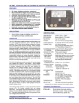
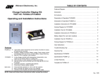
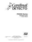
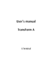
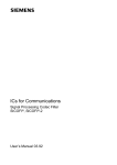
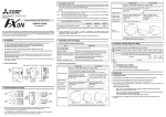
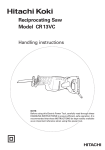
PV CHARGE & LIGHTING CONTROLLER W/ Motion Sensor (15 Amp, 12/24V) PVLC-15MD
FEATURES
v
v
v
v
v
v
v
v
v
PV charge & lighting controller - waterproof
Micro-controller for digital accuracy and reliability
Fully automatic operation on 12V or 24V DC systems
Automatic dusk and dawn lighting control
Motion Sensor activated lighting control.
Will handle up to 15 Amps @ 28VDC from PV panels
and lighting loads up to 15 Amps
Built-in temperature compensation for PV charging
LED indication of solar charge & lighting control
Pulse action reduces battery sulfation
APPLICATIONS
v
Photo Voltaic charge and lighting controller for:
security lighting, roadside rest rooms, etc.
OPERATION
The PVLC-15MD Charge controller monitors both the battery
and PV panel voltage to determine: 12V or 24V DC mode of
operation, if PV panels have sufficient voltage for charge,
and if the battery bank requires charging. When charging
the PVLC-15MD cycles the charge relay every 4 minutes to
re-verify open circuit PV charge voltage to avoid discharging
the batteries through the PV panels when low light conditions
occur. The charge re-connection time is varied by the microprocessor to optimally reduce the charge rate for nearly or
fully charged batteries. The PVLC-15MD internal temperature
compensation adjusts the charge threshold voltages for
optimum charge of the battery bank based on temperatures
between 08C to 458C. For a complete chart PVLC-15MD
Temperature Thresholds section next page.
The PVLC-15MD Lighting controller monitors the motion
sensor, PV panel voltage and battery voltage and initiates
the “light-on” cycle when either the motion sensor has been
activated or a dusk voltage threshold has been reached for
dusk to dawn operation. The relay remains energized until
either the time selection is reached, the PV voltage indicates
dawn, or the battery voltage drops below 11.0V (or 22.0V)
DC for 5 continuous minutes. If the lighting relay drops out
on low battery voltage or is below 12V (24V) at dusk, it will
not re-energize until the battery has been charged up to 12V
(or 24V) DC.
SPECIFICATIONS
SIZE/WEIGHT:
2.0"w x 3.3"l x 1.25"h, 8 ounces
ENCLOSURE:
Epoxy potted in PVC plastic
MOUNTING:
Two 1/2" #8 screws
POWER:
10 to 30 V DC from storage battery
LOAD CAPACITY:
15 Amps @ 28V DC (NO contact)
FUSE REQUIRED:
BUSS 20 Amps AGC or AGX series
PV CHARGE:
On @ 12.7V DC, Off @ 14.2V DC
TIMING RANGE
SWITCH:
(10 Settings)
5 After Dusk Settings
(1 to 4 minutes & All Night)
4 Anytime Settings
(1 to 4 minutes)
1 OFF setting - no lighting
TEMPERATURE
COMPENSATION: 0.040V/8C for 12V systems
CURRENT DRAW:
LED INDICATION:
Red
Yellow
Continuous - [7mA
During charge or lighting - [ 20mA
Charging Mode
Lighting Cycle ‘on’
MINIMUMS:
8V DC battery for PV charge
11V DC battery for lighting relay
PV Charge Current - 80mA
Open PV - 16V (12V system),
TEMPERATURE:
-10 to 758C
RELAY LIFE:
100 million mechanical operations
Double the 12V system values for 24V system values
The PLCM-15MD has ten lighting settings (See PVLC-15MD
switch - lighting adjustments for timing selections). There is
OFF, 4 night only settings, Dusk to Dawn setting, and 4
anytime settings. Selecting (5) “Dusk to Dawn” on the timing
switch causes the lights to turn on at dusk and remain on
until dawn (subject to the low battery voltage cutout).
ORDERING INFORMATION
PVLC-15MD
ATKINSON ELECTRONICS, INC.
Web Site: www.atkinsonelectronics.com
-
Photo-Voltaic charge & Lighting
Controller module W/ motion
detector.
REV 01/06
Distributed by:
PV CHARGE & LIGHTING CONTROLLER W/ Motion Sensor (15 Amp, 12/24V) PVLC-15MD
PVLC-15 TEMPERATURE THRESHOLDS
PVLC-15 SWITCH - LIGHTING ADJUSTMENTS
Below
Between
Between
Between
Between
Between
Between
Between
Above
Pos.
Pos.
Pos.
Pos.
Pos.
Pos.
Pos.
Pos.
Pos.
Pos.
08C
0-58C
5-108C
10-158C
15-308C
30-358C
35-408C
40-458C
458C
-
On @ 13.3V, Off @ 15.0V
On @ 13.3V, Off @ 14.8V
On @ 13.1V, Off @ 14.6V
On @ 12.9V, Off @ 14.4V
On @ 12.7V, Off @ 14.2V
On @ 12.7V, Off @ 14.0V
On @ 12.6V, Off @ 13.8V
On @ 12.6V, Off @ 13.6V
On @ 12.7V, Off @ 14.2V
“0"
“1"
“2"
“3"
“4"
“5"
“6"
“7"
“8"
“9"
-
Off
On for 1 min after sensor activation - night
On for 2 mins after sensor activation
On for 3 mins after sensor activation
On for 4 mins after sensor activation
On from dusk to dawn
On for 1 min after sensor activation - anytime
On for 2 mins after sensor activation
On for 3 mins after sensor activation
On for 4 mins after sensor activation
WIRING DIAGRAM - LIGHTING CONTROL APPLICATION
INSTALLATION AND STARTUP INSTRUCTIONS
1.
2.
3.
4.
5.
6.
7.
Connect the PV panel and lighting load negative wires to the negative battery post. Connect the PVLC-15MD Red (+) wire
to the Battery positive post and the PVLC-15MD Yellow wire to the PV panel + wire. Connect the Motion sensor to the
PVLC-15MD using the 3 wire 18awg cable, red to (+), black to (-), White to (NC), Jumper between (-) and other (C).
Adjust the desired time range on the switch per PVLC-15MD switch lighting options.
Now connect the PVLC-15MD Black wire to the battery negative terminal to power up the PVLC-15MD. Verify that the initial
battery voltage is greater than 11V or 22V, and PV voltage is greater than 16V or 32V.
Twelve seconds after power up, the charge relay (red LED) will click the number of times per the switch position with “0"
being 10. If the switch did not get set to the desired position, disconnect the PVLC-15MD’s negative battery wire and reset
switch to desired lighting operation and timing range. Reconnect the PVLC-15MD's negative battery wire and verify the
desired timing range. If the open circuit PV voltage is above 16V (32V) and the battery voltage is below the “turn on”
threshold (12.7VDC), then the PV charge relay will energize, charging the battery. Every 4 minutes the PV relay will dropout momentarily to test for the presence of adequate PV charge sunlight.
To test the lighting function, wave your hand in front of the motion sensor. If lighting set for night only then disconnect the
PV Yellow wire, wave your hand in front of the motion sensor, the lighting relay (yellow LED) will turn on the lighting load.
Now disconnect the PVLC-15MD black wire and reconnect the yellow PV wire, and then reconnect the black wire.
Mount the PVLC-15MD securely with screws and coat the switch with silicone to insure that the entire module is waterproof.
Waterproof the electrical connections with silicone or grease.
Note:
The PVLC-15MD is powered by either the battery or PV voltage, which ever is greater. The charge relay is only powered
from the PV voltage. If there is insufficient PV voltage when powering up the PVLC-15MD, the charge relay will only
click once after a 12 second delay. If there is sufficient PV voltage( >16V/32V), then after a 12 second delay the PV
relay will click out the switch position with “0" being 10 clicks, it then checks the Battery voltage, if its below the “turn
on” threshold, the charge relay energizes after a delay of 5 seconds. If battery voltage is above the turn on threshold,
then it will wait until it drops below the threshold.
ATKINSON ELECTRONICS, INC.
Web Site: www.atkinsonelectronics.com
REV 01/06
Distributed by:
PV CHARGE & LIGHTING CONTROLLER W/ Motion Sensor (15 Amp, 12/24V) PVLC-15MD
PVLC-15MD WIRE IDENTIFICATION DIAGRAM
TROUBLESHOOTING TIPS
Problem
Solution
-
Module doesn’t click on charge relay and there is sunlight on the PV panels.
Verify that the battery voltage is less than 12.70V (or 25.4V on a 24V DC system) for temperatures between
15-358C (see Temperature Threshold setting previous page) and that the open PV voltage is greater than 16V
or (32V). If both conditions are met, wait for the 4 minute delay period to cycle.
Try resetting the PVLC-15MD by disconnecting the Black wire for 10 seconds and then reconnecting it,
PVLC-15MD will go thru it’s startup routine and click out the switch settings, then to normal operation.
Problem
Solution
-
Module clicks every several minute .
This is the normal operating sequence.
Problem
Solution
-
Module charges for a few seconds then shuts off for 4 minutes.
The Batteries are fully charged and the charge current was at maximum output, verify battery voltage is greater
than 14.2VDC. It may also mean that the Batteries have a poor connection or a bad cell with high internal
resistance.
Problem
Solution
-
Module switches on for 1 or 2 minutes and then is off for a much longer period of time.
This is also normal if the battery is at or nearly fully charged and the PV charge current is at or near maximum.
Problem
-
Solution
-
The battery load has been left on and the storage battery has discharged below 8V DC. The PV system is not
charging when the load is turned off.
The PVLC-15MD needs at least 8V DC from the battery to operate properly. Place the panel in direct sunlight
and jumper the red and yellow wires for a few minutes, thus bypassing the charge controller allowing the
battery voltage to rise to at least 8V DC. Disconnecting the jumper will allow the PVLC-15 to charge the
battery up to normal levels.
Problem
Solution
-
The module is set for lighting control and at dusk fails to turn on lights.
The PVLC-15MD checks the battery voltage at dusk to see if batteries are greater than 12V (or 24V) DC,
sufficient to run lights. If not, it locks out lighting relay until the solar panels have charged battery above 12V
DC (24V DC).
Problem
Solution
-
The motion detector does not indicated movement after power up.
The motion detector has a 30 to 45 second delay before sensing movement.
ATKINSON ELECTRONICS, INC.
Web Site: www.atkinsonelectronics.com
REV 01/06
Distributed by: