1
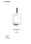
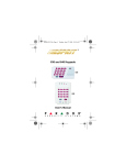
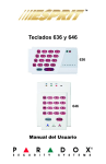
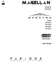
Dual-band radio transmitter
T10, Т10С
T10U, T10UC
(v.YYMMDD)
Installation manual
www.trikdis.com
1
Contents
Safety requirements ................................................................................................................................................................. 3
Transmitter function ................................................................................................................................................................ 3
Operation ................................................................................................................................................................................. 3
Outside view ............................................................................................................................................................................ 4
Installation ............................................................................................................................................................................... 5
Wiring diagrams ...................................................................................................................................................................... 5
Setting of operating parameters .............................................................................................................................................. 6
Restoring factory default settings........................................................................................................................................... 10
Firmware update .................................................................................................................................................................... 10
Technical specifications .......................................................................................................................................................... 10
Package contain...................................................................................................................................................................... 10
Annex. Configuration of authorization and access restricting for another user ..................................................................... 11
2
Safety requirements
Before using the transmitter, make sure to read these instructions and follow safety requirements.
Transmitter installation and servicing may only be carried out by qualified personnel with knowledge about low-voltage
and radio transmitting equipment and complying with safety requirements.
T10 transmitter is mounted in limited-access areas at safe distance from the radio-emission sensitive electronic
equipment.
Transmitter function
T10 is a transmitting device applied for transmitting messages of intruder and fire alarm systems to a monitoring and alarm
receiving center (MARC) at specified licensed VHF or UHF radio frequency. The transmitter must be connected to a control
panel for transmitting collected signals or messages of control panel whereas radio receiver of MARC receives of these and
directs to alarm monitoring software. Features:
-
-
Transmitters with modifications T10 and T10C transmits at VHF radio frequency whereas transmitters with
modifications T10U and T10UC transmits at UHF radio frequency;
One transmitter transmits information of two secured objects with two object ID numbers
Each transmission can encoded with two different transmission protocols and transmitted at two licensed radio
frequencies;
Transmitters with modifications T10 and T10U transmit messages collected from data bus of control panel whereas
transmitters with modifications T10C and T10UC transmit messages if their input status changes due to event has
occurred in alarm system;
all operating parameters are set with the software T10config via USB port;
Operation
Received messages from control panel are transmitted at licensed radio frequency and format are set. Transmitter’s
message consists of the transmitter or repeater tag, transmitter or object identification number (object ID) and event code.
Transmitter can be set to broadcast information of two secured objects at two radio frequencies.
Most of the modern control panels create message on the event in Contact ID format, which is described in SIA DC-051999.99 standard. If the transmitter is set to encode transmission at RAS-3_CID format, then Contact ID message is
transmitted unchanged. In order to synchronize transmitter with the existing receiving equipment, other suitable
transmission encoding formats can be set. However, other formats cannot encode full Contact ID, thus they will be converted
to the UNI codes. The conversion table can be edited. If MARC uses receiving equipment of TRIKDIS, thus received UNI code is
directed to existing alarm monitoring software at compatible format.
To the transmitter input IN (programmable type NC/NO/EOL=2,2 kΩ) external circuits can be connected. When input is
triggered, transmitter broadcasts the set message.
Transmitter periodically sends test messages. Timely receipt of those reports is inspected by the monitoring software.
Transmitter automatically monitors power supply voltage. If voltage falls below 11,5 V threshold, the transmitter will
send a report about power supply failure. If voltage rises above 12,6 V threshold, the transmitter will send a report about
power supply restoring.
When power supply voltage falls below 10 V thresholds, the transmitter will send a report on switching to sleep mode.
In sleep mode transmitter does not collect or send any messages. If transmitter operates in sleep mode and power supply
voltage rises above 12,6 V threshold, then the transmitter will start operating in working mode and will send the test
message.
3
Outside view
1.
2.
3.
4.
5.
6.
Terminal block
USB port and button RESET
Antenna connector
Indicator Network
Indicator Data
Indicator Power
Meaning of the terminals
Transmitter T10, T10U terminals
Description
+12V power supply input
Common ground
Synchronization signals terminal
Data signals terminal
1st input terminal for connection of external circuits (type NC/NO/EOL=2.2 kΩ can be set)
Output terminal (will be used in future)
2nd input terminal for connection of external circuits (type NC/NO/EOL=2.2 kΩ can be set)
Common ground
For future use
Transmitter T10C, T10UC terminals
Description
+12V power supply input
Common ground
1st input terminal for connection of external circuits (type NC/NO/EOL=2.2 kΩ can be set)
2nd input terminal for connection of external circuits (type NC/NO/EOL=2.2 kΩ can be set)
3rd input terminal for connection of external circuits (type NC/NO/EOL=2.2 kΩ can be set)
4th input terminal for connection of external circuits (type NC/NO/EOL=2.2 kΩ can be set)
5th input terminal for connection of external circuits (type NC/NO/EOL=2.2 kΩ can be set)
Common ground
For future use
+E
COM
CLK
DATA
IN1
OUT1
IN2
COM
MCI
+E
COM
IN1
IN2
IN3
IN4
IN5
COM
MCI
LED indication
LED
Network indicates message
status
Data indicates data
exchange
Power indicates the power
status, programming mode
Operation
Meaning
Constant yellow
Message is sent
Constant green
green flashing
red flashing
green flashing
yellow flashing
Green and yellow in turn flashing
Unsent messages in memory are present
Messages from control panel are incoming
Transmitter operating in sleep mode
Power supply voltage is sufficient.
Power supply voltage is insufficient (≤11,5 V),
Programming mode
4
Installation
Actions
Comments
1. Set the transmitter operating parameters.
See: Setting of operating parameters
2. Mount the transmitter inside control panel‘s
metal casing.
Mounting and antenna holes position and dimensions:
3. Screw the antenna to the transmitter.
4. According to wiring diagrams, connect the
transmitter to external equipment.
5. Turn on power supply.
6. According to the operation of LED indicators,
assess whether the transmitter is operating
properly.
7. Make sure that the radio receiver receives
messages transmitted by the transmitter.
See: Wiring diagrams.
See: LED indication.
If message receiving level is low, more efficient antennas
should be used or the radio transferring system should be
enlarged by the using radio repeaters network.
Wiring diagrams
Transmitter T10, T10U can be connected to the widespread control panels:
Compatible control panel models
Manufacturer
DSC®
PYRONIX®
GE®
PARADOX®
PARADOX®
PARADOX®
PARADOX®
Compatible control panel models
PC585, PC1565, PC5020, PC1616, PC1832, PC1864
MATRIX 424, MATRIX 832, MATRIX 832+, MATRIX 6, MATRIX 816
CADDX NX-4, NX-6, NX-8
SPECTRA SP5500, SP6000, SP7000, 1727, 1728, 1738
MAGELLAN MG5000, MG5050
DIGIPLEX EVO48, EVO192, NE96, EVO96
ESPRIT E55, 728ULT, 738ULT
Transmitter T10, T10U connecting to DSC® Power
Series control panels.
Transmitter T10, T10U connecting to PARADOX® control
panels.
Transmitter T10, T10U connecting to PYRONIX® Matrix
Series control panels.
Transmitter T10, T10U connecting to GE® Caddx control
panels.
5
T10, T10U transmitter functionality can be increased by connecting interfaces C11, C14 or CZ6. Interface operation and
wiring are presented in particular interface installation manual.
Presumable interface usage
Interface
C11
C14
CZ6
Purpose of interface
It directs control panel’s Contact ID report by DTMF tones to the Transmitter to be transmitted at set licensed radio frequency.
It directs control panel’s Contact ID report by DTMF tones to the Transmitter to be transmitted at set licensed radio frequency or
commutates land line to be transmitted to PSTN receiver.
In this case alarm messages can reach monitoring station receiver via main and/or backup communication channel.
Increases amount of inputs up to 6 (EOL=2,2 kΩ).
Transmitter T10С, T10UC can be connected to any control panel’s PGM outputs or used as a standalone security device:
Transmitter T10C, T10UC connecting to control panel.
Input type set as NO or NC.
Transmitter T10C, T10UC connecting to control panel. Input
type set as EOL=2,2 kΩ.
Setting of operating parameters
Software T10config applied for setting of operating parameters can be downloaded from the www.trikdis.com website.
In order to limit the ability to change the transmitter settings, user access control is implemented in two ways:
a)
User Access control using password stored in the transmitter memory:
Software user who is authorized to use more of the following features will be called Admin, and the lower-level user whose
rights are more restricted will be called User. After logging in with the password of User these features are available, that
are identified by Admin only. After logging in with the password of Admin, you can use all available features and restrict
permissions to User. See Annex. Configuration of authorization and access restricting for another user.
b) Software features control, using file stored in T10config folder:
Software distributor may limit its functionality and determine appropriate rights to customer. Permission settings are
stored in license.lic file that may be provided due to distributor and customer agreement. If the software during start-up
will be unable to read settings from permissions file, then it will run in DEMO mode, i.e. maximum restrictions will be set.
Permissions file *.lic is loaded with menu commands File/Import. See Annex. Configuration of authorization and access
restricting for another user.
6
1.
Connect T10 transmitter to PC‘s USB port.
Note: USB driver must be installed on PC. When the transmitter is connected to PC for the first time, MS Windows should
open the USB driver installation window - Found New Hardware Wizard. Download MS Windows USB driver from
www.trikdis.com website. In the wizard window select the option Yes, this time only and click Next button. After Please
choose your search and installation options window is opened, click Browse button and specify the location where USB
driver was saved. Follow the wizard and perform all the remaining steps to install the USB driver.
2.
3.
Run T10config software.
Select the branch named Settings.
In field Port you must select a port that transmitter is connected to.
A specific port occurs only when transmitter is connected and USB driver
is installed properly. See Connect T10 transmitter to PC‘s USB port.
From Language field select preferred user interface language.
4.
Click Device info button.
When the transmitter is connected to PC, Power indicator should flash
green and yellow in turn. In T10config software‘s status bar should be
displayed connection status Connected and information about the
connected transmitter:
Product number;
Transmitter serial number;
Boot-loader version;
Transmitter firmware version.
5.
Click Device info button.
When the request window Access Code appears enter log-in password
(default password - 1234), then click OK.
If you want the software to remember your Access code, check the box
Remember. When connecting next time, you won’t be prompted for
password again.
6.
Select the branch named Main and set the required parameters:
7
7.
User password
User user‘s password box. To change this password, click Change button next to the box and in
newly opened window enter desired value;
Admin password
Admin user‘s password box. To change this password, click Change button next to the box and in
newly opened window enter desired value; See Annex. Configuration of authorization and
access restricting for another user.
Protocol
List of radio systems. Select the encryption protocol compatible with the radio receiver. If the
transmitter is set to any other protocol than RAS-3_CID, then the received ContactID message
will be converted to manufacturer‘s predefined UNI code. Conversion table can be seen in the
Tools menu option under CID to UNI table… and by clicking Read [F7] in newly opened window.
In the conversion table, symbol “?“ means any decimal number (0-9). Edit the table only when
necessary. The table is loaded into the transmitter memory by clicking Write [F6] button. By
clicking Save [F5] button, conversion table will be saved to PC; clicking Load button will load file
into the software.
Account ID
Field for entering transmitter‘s object identifier;
System
Field for entering radio subsystem number;
Group
Field for entering a number of radio group;
RF name
List for selecting names provided to radio frequencies;
Event transmit
time(s)
List for selecting the number of broadcasts for same message (recommended value – 3).
Test event
repetitions
List for selecting the number of Test broadcasts (recommended value – 2).
Security panel
From this list select the interface control panel model which is connected to T10, T10U
transmitter. If C11, C14 or CZ6 interface is connected – select INTERFACE C11, C14, CZ6 from the
list.
Transmitter parameters in Reports branch. To change the settings each field should be double-clicked and in newly
opened window desired values should be entered:
Event codes
Transmitter event parameters input fields.
Test – enter in this field Test message sending parameters: send/don‘t send Test message; Test
8
broadcasting via first or second radio frequency;
Low power – enter in this field parameters for power supply events: send/don‘t send message;
too low voltage (less than 11,5 V) event code and restore to operating condition (over 12,6 V)
event code via first or second radio frequency;
Sleep mode code – enter in this field parameters for sleep mode events: send/don‘t send
message; event code when voltage falls below 10 V threshold via first or second radio frequency;
Parameters changed code – enter in this field parameters for transmitter parameter changes:
send/don‘t send message; event code for sending via first or second radio frequency;
Service code – enter in this field parameters for repeaters network testing code: send/don‘t send
message; event code for sending via first or second radio frequency;
Program error – enter in this field parameters for transmitter‘s internal error: send/don‘t send
message; event code for sending via first or second radio frequency;
Input report settings
Area that stands for entering reports of signals from the external circuits
Fields for IN message parameters
Transmitter inputs IN1, IN2 event description field. Type – type of input circuit (NC/NO/EOL);
Delay – minimal trigger‘s exposure time (ms); Event code and Restore code – input triggering
event and restore codes for sending via first or second radio frequency;
Test event
Area that stands for additional Test message parameters
Period - Test message broadcasting period (hr. and min.);
Delay – delay for sending first Test message (hr.) after powering on the transmitter
Send when are no events – Test message will be sent only when there will be no events generated
during the set Period.
8.
Choose Settings branch and set preferred parameters:
Port
See “Select the branch named Settings”
Language
List for selecting user interface language.
Allow user to change
User will be allowed to change operating parameters are marked only.
9
Available radio frequencies
Table of frequency names that can be chosen by selecting RF name parameter. If you need
to supplement the table, click Add button. In newly opened window, type the name of
radio frequency, its meaning in Hz and click OK.
After entering the desired transmitter settings values, click the button Write [F6] and the transmitter T10 will be loaded
with these.
9.
10. Disconnect USB cable from transmitter.
Save [F5]
When clicking the button all settings and values from software fields can be stored in your
computer. The file with extension .gst will be created. This file can be opened by clicking Open [F3]
button and can be used as a template for programming other transmitters.
Restore [F11]
The button is used for restoring default settings of the transmitter. After query window appears,
click OK button.
Restoring of factory default settings
There is an option to restore factory setting to the transmitter:
1.
Complete items 1-4 as described in the chapter Setting of operating parameters.
2.
Click Restore [F11] button. After query window appears, click OK button.
Updating of firmware
When new performance characteristics are added by manufacturer, it is possible to update previously purchased
transmitter‘s firmware:
1.
Download the latest T10_vx.xx.prg file from www.trikdis.com website.
2.
Complete items 1-4 as described in the chapter Setting of operating parameters.
3.
In T10config software select the branch named Firmware, then load from PC earlier saved T10_vx.xx.prg file.
4.
Click Start [F9] button. In newly opened query window, enter Admin access code and click OK button.
Firmware process is finished only when a progress bar is fully filled up. Disconnect USB cable from transmitter.
10
Technical specifications
Supply voltage
Current consumption
Radio frequency range
Operating frequency count
Maximum radiated power
Antenna output impedance
Secondary (collateral) emissions
Broadcasting time
Broadcasting repeat count
Message buffer capacity
Inputs IN to connect external circuits
Configuration of settings
Working range
Dimensions
Constant voltage from 10 to 15 V
Up to 60 mA in standby;
Up to 800 mA when broadcasting
Radio frequency programmed with T10config configuration software:
transmitters T10, T10C: VHF band from 146 MHz to 174 MHz;
transmitters T10U, T10UC: UHF band from 410 MHz to 470
MHz.
Up to 2 frequencies
4,95 W
50 Ω
Meets the requirements of EN 300 113
From 60ms to 400ms depending on the selected radio system
Selectable from 1 to 8 times
Up to 100 events
optional NC/NO/EOL=2,2 kΩ type
T10config software via USB port
Temperature from -20 °C to 55 °C, relative air humidity up to 90 % at +20 °C
65 x 135 x 25 mm
Transmitter broadcasting protocols and compatibility with the radio receiver
TRIKDIS R7
TRIKDIS RF7
TRIKDIS R11
TRIKDIS RF11
Other manufacturers
RAS-002
+
+
RAS-2M
+
+
LARS
+
+
LARS1
+
+
+
+
+
+
Package content
Transmitter
Resistor (2,2 kΩ)
RAS-3_xxx
1 pcs.
2 pcs.
11
Annex. Configuration of authorization and access restricting for another user
It is possible to restrict access for other users to change all operating parameters of transmitter and just allow them
changing desired part of operating parameters only.
User permissions setting:
Admin can establish the password value of the User in the folder Main. Permissions allowed particular User changing
operating parameters are established in the folder Settings. Admin can allow User to change only part of the transmitter
parameters by checking only appropriate boxes in Allow user to change list.
Any user of the software can give to another user as many rights as he has
(or less) and create license file.
License file is created from menu by command File/Export. In newly
opened Export license window other user‘s rights can be restricted.
Licensed to
The field for entering customer‘s name. It will be displayed in main window title.
Export
The table is for selecting particular frequencies witch are allowed other software’s user using.
Allow edit frequencies
If checked, other software’s user can edit the table Available radio frequencies.
Allow user to change
Other software user will be allowed to change only the parameters marked with a tick.
When the button OK is clicked, the window Save As will be opened. New file name should be given and desired folder
selected. Newly created license file is saved by the clicking button Save.
12