1
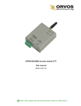
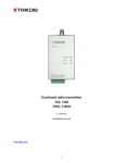
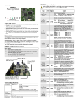
Printer Module V1.2
PRT3
Entering EVO Programming
Entering Spectra Programming
1. Hold [0] key + [INSTALLER CODE]
2. Enter section [953] (DGP-848) [4003] (EVO)
3. Enter module’s 8-digit [SERIAL NUMBER]
4. Enter [SECTION] and enter the required [DATA]
1. Press the [ENTER] key
2. Enter the [INSTALLER CODE]
3. Enter 3-digit [SECTION] you wish to program
4. Enter the required [DATA]
EVO
Spectra
Sections Sections
Enable Serial Port
EVO
Spectra
Sections Sections
Partition Assignment
Printed in Canada 09/2009
PARADOX.COM
PRT3-EI02
[001]
[550]
Digiplex - Options [1] to [8]
Spectra - Options [1] to [2]
[002]
to
[013]
[551]
to
[552]
Automatic Printing of Zone Status
The Printer Module (PRT3) provides the ability to automatically print live or stored events.
Home Automation Interface Capabilities
When used with an EVO Series or DGP-848 (V4.11 or higher) control panel, the Printer Module can also
be used as an interface between a home automation system and your control panel. For information on
this feature and its related programming sections, refer to the ASCII Protocol Programming Instructions
and/or C-Bus Programming Instructions available on our website at paradox.com.
[014]
[550]
Minimum 80 column printer
1 start bit, 8 data bit, no parity and 1 stop bit (8N1)
9-16 Vdc
60mA maximum
2400, 9600, 19200 or 57600 bps
2048 events
EVO48, EVO96, EVO192, DGP-848 or DGP-NE96 control panel
Spectra 1728 or 1738 control panel (V2.0 or higher)
PRT3 can be used to replace a PRT1
[2] Arming/Disarming Events
[3] Alarm and Alarm Restore Events
[4] Tamper and Tamper Restore Events
[5] Trouble and Trouble Restore Events
[6] Special Events**
[7] Access Events ***
* Fire Reset, Contact Module Access, Remote Access, PC Fail To Com, User
Code Entered, Bypass Programmed, Delay before Transmitting and Utility Key
Pressed
** Cold Start, Warm Start, Test Reports, WinLoad Login/Logout, Installer In/Out
*** Access Granted/Denied, Request For Exit, Door Left Open Alarm, Door Left
Open Restore, Door Forced Alarm, Door Forced Restore
[4] Arming/Disarming Events
[5] Alarm & Alarm Restore Events
[6] Tamper & Tamper Restore Events
[7] Trouble & Trouble Restore Events
[8] Special
†
Events†
[015]
[553]
(see below for Special Events)
TX:
Condition:
ON
OFF
OFF
Combus shorted (GND or VCC / No clock / No data
Setting the Date (Spectra)
ON
OFF
ON
Wrong data / Invalid combus address (Too many modules)
ON
ON
OFF
Reserved for future use
ON
ON
ON
Combus lines are reversed (Clock in Green / Data in Yellow)
FLASH
OFF
OFF
Low power
RX
Printer module is receiving information
TX
Printer module is sending information
[016]
N/A
[020]
to
[025]
N/A
Option [4]
Set the Printer Module’s serial port usage to either Event Reporting (off) or Home
Automation (on).
Note: For information on using the Printer Module as an interface for a home
automation system, refer to the ASCII Protocol Programming Instructions and/or CBus Programming Instructions available on our website at paradox.com.
Automatic Printing of Zone Status
Each section represents 8 zones i.e. [020] = zones 97~104, [025] = zones
137~144. The Printer Module must be assigned to the same partition as the zone.
Manual Event Group Printing
The event groups are represented by the following sections:
EVO
-Option [1]
Spectra -Option [4]
ERROR: RX:
Condition:
Option [2] [3]
Both the Printer Module and serial port should have the
same baud rate. Refer to the printer’s instruction manual
for the correct baud rate.
Serial Port Usage
Printer Status Mask Options
[553]
Panel Bus
LED:
[553]
Event
Group
Feature
Group
Start #
End #
Miscellaneous Events
[027]
[028]
[029]
[030]
Arming/Disarming Events
[031]
[032]
[033]
[034]
Alarm/Alarm Restore Events
[035]
[036]
[037]
[038]
Tamper/Tamper Restore Events
[039]
[040]
[041]
[042]
Trouble/Trouble Restore Events
[043]
[044]
[045]
[046]
Special Events
[047]
[048]
[049]
[050]
Access Events
[051]
[052]
[053]
[054]
All Events
[055]
[056]
[057]
[058]
Enable Parallel Port
[015]
Serial Bus
[016]
[PG] & [FNC1] keys pressed, Button Pressed on Remote, Bypass
Programming, User Activated PGM, Breaching Zone with Delay and
System Power Up.
EVO Spectra
[3]
[5]
Off-Line Status Mask
[4]
[6]
Paper-Empty Status Mask
[5]
[7]
Printer Fault Status Mask
[6]
[8]
Printer Busy Status Mask
If the Printer Status Mask Options are ignored, printer troubles will not be
displayed. These options apply only to the parallel port.
LED Feedback
Baud Settings
Spectra
Printer Requirements
Dot matrix, inkjet or laser printers can be connected through one of your computer’s COM ports to the
Printer Module’s serial port. Events can be displayed and printed using communication software like
Procomm™, Telix© and HyperTerminal®.
It is recommended that only dot matrix printers that support a minimum of 80 columns be connected
directly to the Printer Module. Only dot matrix printers can print individual events in real time.
Each section represents 8 zones i.e. [002] = zones 1~8, [013] = zones 89~96.
The Printer Module must be assigned to the same partition as the zone.
[1] Miscellaneous Events *
Sample Printout:
2007/06/12 07:17 Partition 1 Arming with master
John Doe
2007/06/12 18:09 Partition 1 Disarming with master John Doe
Parallel Port:
Serial Port:
Input Voltage:
Current Consumption:
Serial Port Baud Rates:
Event Buffer:
Compatibility:
[553]
Automatic Printing of Event Groups
EVO
Introduction
Technical Specifications
[016]
Option [1]
The Printer Module can use the HyperTerminal® communication program that
comes installed with Windows®. Using HyperTerminal®, the Printer Module will
display events as they occur on your computer’s monitor.
1. Click Start (from the Windows® taskbar) D Programs D Accessories D
Communications D HyperTerminal®. The Connection Description window
is displayed.
2. Enter a name in the Name text box and select an icon for your connection file.
Click OK. The Connect To window is displayed.
3. From the Connect Using drop-down list select the COM port connected to the
Printer Module. Click OK. The COM Properties window is displayed.
4. Click on the Bits per second drop-down list and select the baud rate that is set
in the Printer Module (Section [016] Options [2] & [3]). By default,
HyperTerminal® sets the Data bits at 8, the Parity at None and the Stop bits at
1. Click OK.
5. The HyperTerminal® display will appear already connected to the Printer
Module. Click on the Properties icon (or select Properties from the File menu).
The communication file’s Properties window is displayed. Click the Settings tab.
Under Emulation, verify that it is set as Auto Detect. If not, select Auto Detect
from the drop-down list. Click OK.
N/A
[557]
N/A
[280]
[027]
to
[058]
N/A
Each group of sections from [027] to [058] represents event groups that can be
printed when a specified action from the PGM Programming Table occurs (see the
control panel’s programming guide).
Event Groups 000 to 055 can be used to program the Printer Module’s
Manual Printing feature. Event groups 062 and 063 can only be used when
using an EVO control panel.
After a power failure, the date must be reprogrammed.
Setting the Time (Spectra)
After a power failure, the time must be reprogrammed.
[060]
to
[065]
Automatic Printing of Zone Status
N/A
Each section represents 8 zones i.e. [060] = zones 145~152, [065] = zones
185~192. The Printer Module must be assigned to the same partition as the zone
Paradox Memory Key (NOT TO BE USED WITH UL LISTED SYSTEMS)
[080]
and
[090]
[902]
and
[900]
The Paradox Memory Key can copy the programmed contents of one PRT3
into as many others as needed. For more information, see the control panel’s
programming guide.
EVO Spectra
[090] [902] = Copy to Memory Key
[080] [900] = Paste to PRT3
When the PRT3 emits a confirmation beep, wait for a second confirmation beep and
then remove the Memory Key.
Press the PRINT TEST
switch to perform a
print test
PRT3
paradox.com
Print
Test
To Control Panel
+
-
AUX
PANEL BUS
ERROR
RX
TX
Memory
Key
1
1
SERIAL
USB
RX
TX
GRN YEL
Combus
USB
PORT
RED BLK GRN YEL
+
-
GRN
YEL
6
2
3
Pin 5 - GND
Pin 4 - DTR (Data Terminal Ready/ Not Used)
Pin 8 - CTS (Control Transmission/ Not Used)
Pin 3 - TX
4
Home
Automation
Module*
5
C-Bus
PC Interface*
Pin 2 - RX (Not Used in Event Reporting)
* EVO control panels only.
1. See “LED Feedback” on page 1
2. 25-Pin Parallel Port: Connect the Printer Module’s 25-pin parallel port to any dot matrix printer.
Note: The dot matrix printer must support a minimum of 80 columns.
3. 9-Pin Serial Port: Connect the Printer Module’s 9-Pin serial port to a dot matrix printer.
Note: The dot matrix printer must support a minimum of 80 columns.
4. 9-pin Serial Port: Connect the Printer Module’s 9-pin serial port to a home automation module.
5. 9-pin Serial Port: Connect C-Bus to the Printer Module using a null modem cable.
6. 9-pin Serial Port: Connect either the Printer Module’s USB or 9-pin serial port to a computer’s COM port to view the control panel’s events on the computer’s
monitor. The events display on the monitor can then be printed through the printer connected to the computer.
Remove AC power and battery before adding a module to the system. Please refer to the control panel’s Reference & Installation Manual for the
maximum allowable installation distance.
Only one PRT3 can be connected per Spectra control panel.
Note: Printer cable length must not exceed 25ft.
Warranty
For complete warranty information on this product please refer to the Limited Warranty Statement found on the website www.paradox.com/terms. Your use of the Paradox product signifies your acceptance
of all warranty terms and conditions.
© 2009 Paradox Security Systems Ltd. All rights reserved. Specifications may change without prior notice. One or more of the following US patents may apply: 7046142, 6215399, 6111256, 6104319,
5920259, 5886632, 5721542, 5287111, 5119069, 5077549 and RE39406 and other pending patents may apply. Canadian and international patents may also apply.
Spectra, Digiplex and EVO are trademarks or registered trademarks of Paradox Security Systems Ltd. or its affiliates in Canada, the United States and/or other countries.